METER / GAUGE / DISPLAY METER / GAUGE SYSTEM B150718 Turn Signal Light Circuit Current Below Threshold
DESCRIPTION
| DTC No. | Detection Item | DTC Detection Condition | Trouble Area |
|---|---|---|---|
| B150718 | Turn Signal Light Circuit Current Below Threshold | Diagnosis Condition:
Battery voltage is 10 V or more Malfunction Status:
·
Open in front turn signal light circuit ·
Open in side turn signal light circuit ·
Open in rear turn signal light circuit |
w/ Headlight ECU:
·
Front turn signal light socket ·
Headlight unit assembly ·
Headlight ECU sub-assembly ·
Side turn signal light assembly ·
Outer rear View mirror assembly (w/ Panoramic View Monitor System) ·
Outer mirror retractor (w/o Panoramic View Monitor System) ·
Rear combination light socket and wire sub-assembly ·
Combination meter assembly ·
Harness or connector w/o Headlight ECU, for TAW Made:
·
Headlight assembly ·
w/ Front Fender Type Side Turn Signal Light: Side turn signal light socket and wire ·
w/ Outer Rear View Mirror Type Side Turn Signal Light: Side turn signal light assembly Outer rear view mirror assembly (Outer mirror retractor) ·
Rear combination light assembly ·
Combination meter assembly ·
Harness or connector w/o Headlight ECU, except TAW Made:
·
Front turn signal light socket ·
w/ Front Fender Type Side Turn Signal Light: Side turn signal light socket and wire ·
w/ Outer Rear View Mirror Type Side Turn Signal Light: Side turn signal light assembly Outer rear view mirror assembly (Outer mirror retractor) ·
Rear combination light socket and wire sub-assembly ·
Combination meter assembly ·
Harness or connector |
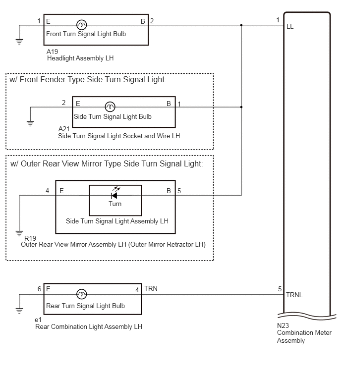
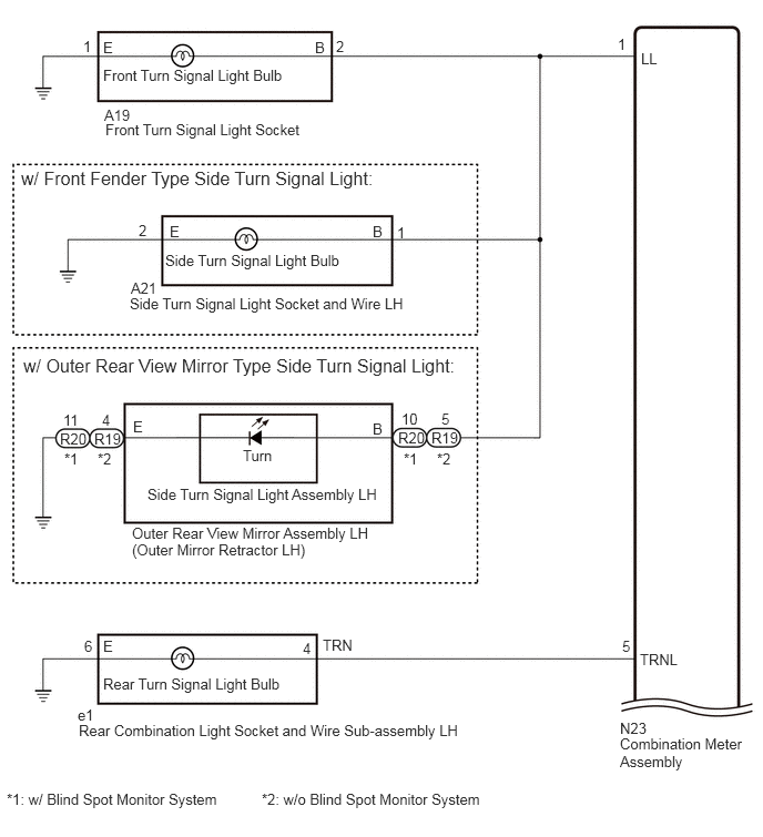
WIRING DIAGRAM
w/ Headlight ECU:
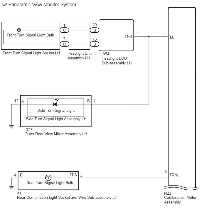
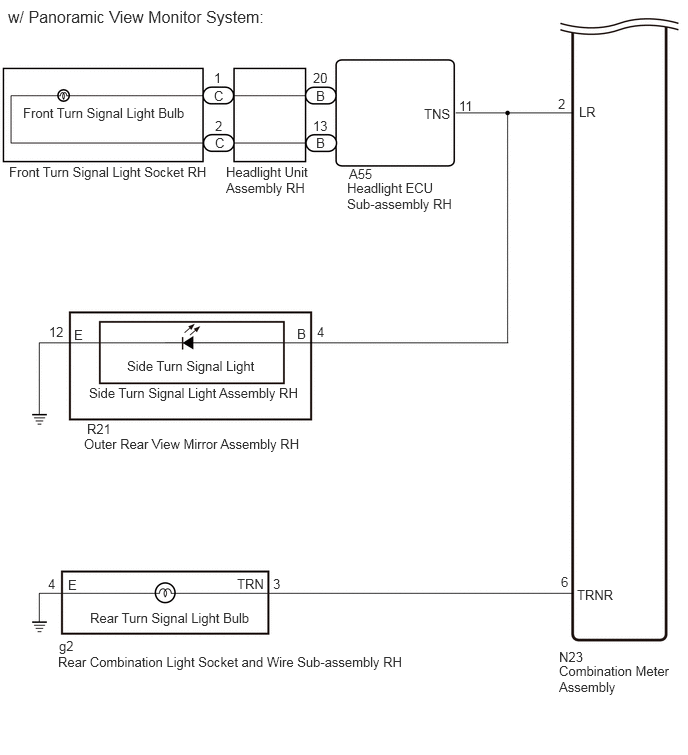
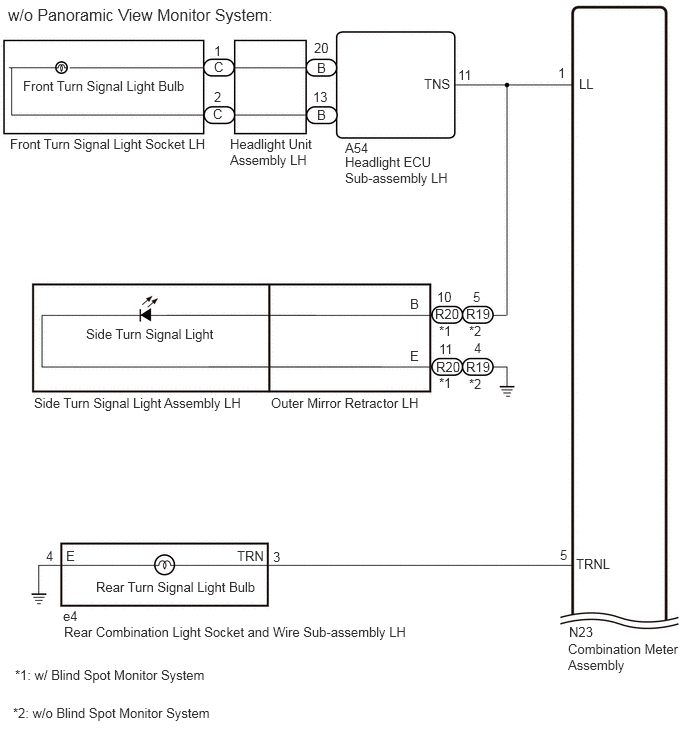
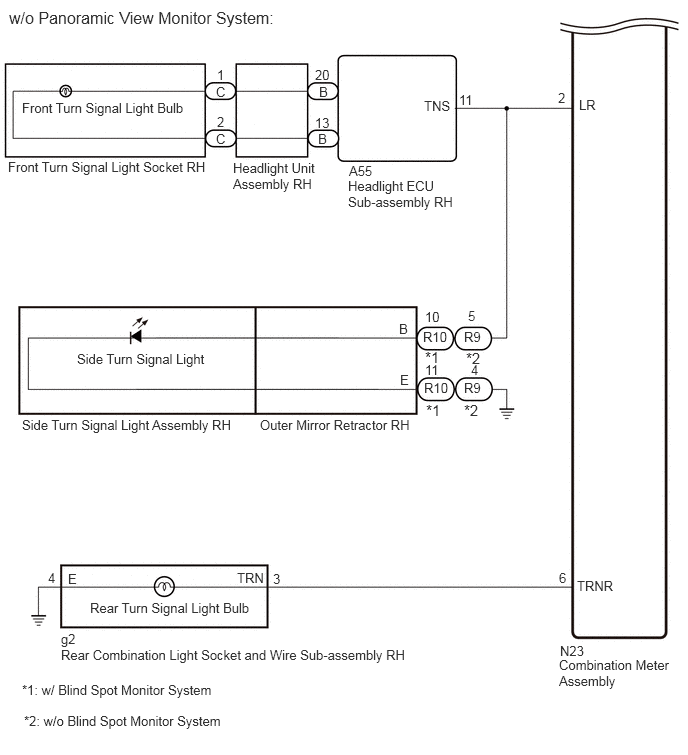
w/o Headlight ECU, for TAW Made:

w/o Headlight ECU, except TAW Made:
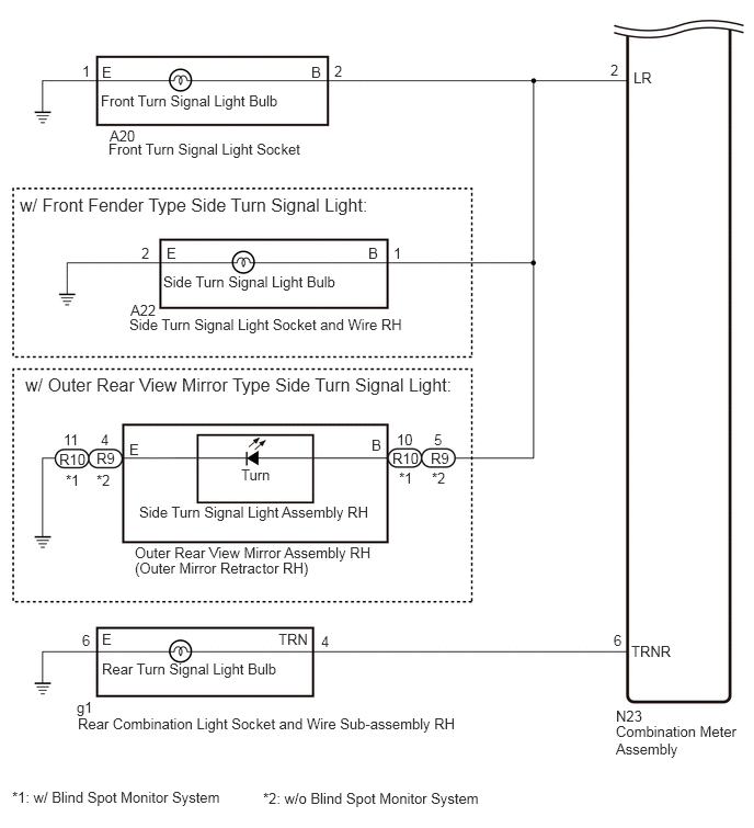
CAUTION / NOTICE / HINT
- NOTICE:
- ·
When replacing the combination meter assembly, always replace it with a new one. If a combination meter assembly which was installed to another vehicle is used, the information stored in it will not match the information from the vehicle and a DTC may be stored.
·When replacing the headlight ECU sub-assembly LH, always replace it with a new one. If a headlight ECU sub-assembly LH which was installed to another vehicle is used, the information stored in it will not match the information from the vehicle and a DTC may be stored.
·Inspect the bulbs before performing the following procedure.
PROCEDURE
Check vehicle condition.
- Result:
Result Proceed to w/o Headlight ECU A w/ Headlight ECU B
A
B
Inspect the illumination of each turn signal light.
- Result:
Result Proceed to Front turn signal light LH and side turn signal light LH do not blink. A Front turn signal light RH and side turn signal light RH do not blink. B Front turn signal light LH does not blink. C Side turn signal light LH does not blink. D Front turn signal light RH does not blink. E Side turn signal light RH does not blink. F Rear turn signal light LH does not blink. G Rear turn signal light RH does not blink. H
A
B
C
D
E
F
G
H
Check vehicle condition.
- Result:
Result Proceed to for TAW Made A except TAW Made B
A
B
Disconnect the N23 combination meter assembly connector.
Disconnect the A19 headlight assembly LH connector.
Measure the resistance according to the value(s) in the table below.
- Standard Resistance:
Tester Connection Condition Specified Condition A19-2 (B) - N23-1 (LL) Always Below 1 Ω
- Result:
Proceed to OK NG
OK
NG
Disconnect the N23 combination meter assembly connector.
Disconnect the A19 front turn signal light socket connector.
Measure the resistance according to the value(s) in the table below.
- Standard Resistance:
Tester Connection Condition Specified Condition N23-1 (LL) - A19-2 (B) Always Below 1 Ω
- Result:
Proceed to OK NG
OK
NG
Check vehicle condition.
- Result:
Result Proceed to for TAW Made A except TAW Made B
A
B
Disconnect the N23 combination meter assembly connector.
Disconnect the A20 headlight assembly RH connector.
Measure the resistance according to the value(s) in the table below.
- Standard Resistance:
Tester Connection Condition Specified Condition A20-2 (B) - N23-2 (LR) Always Below 1 Ω
- Result:
Proceed to OK NG
OK
NG
Disconnect the N23 combination meter assembly connector.
Disconnect the A20 front turn signal light socket connector.
Measure the resistance according to the value(s) in the table below.
- Standard Resistance:
Tester Connection Condition Specified Condition N23-2 (LR) - A20-2 (B) Always Below 1 Ω
- Result:
Proceed to OK NG
OK
NG
Check vehicle condition.
- Result:
Result Proceed to for TAW Made A except TAW Made B
A
B
Disconnect the A19 headlight assembly LH connector.
Disconnect the N23 combination meter assembly connector.
Measure the resistance according to the value(s) in the table below.
- Standard Resistance:
Tester Connection Condition Specified Condition A19-2 (B) - N23-1 (LL) Always Below 1 Ω A19-1 (E) - Body ground Always Below 1 Ω
- Result:
Proceed to OK NG
OK
NG
Disconnect the A19 front turn signal light socket connector.
Disconnect the N23 combination meter assembly connector.
Measure the resistance according to the value(s) in the table below.
- Standard Resistance:
Tester Connection Condition Specified Condition A19-2 (B) - N23-1 (LL) Always Below 1 Ω A19-1 (E) - Body ground Always Below 1 Ω
- Result:
Proceed to OK NG
OK
NG
Check vehicle condition.
- Result:
Result Proceed to w/ Front Fender Type Side Turn Signal Light A w/ Outer Rear View Mirror Type Side Turn Signal Light B
A
B
Disconnect the A21 side turn signal light socket and wire LH connector.
Disconnect the N23 combination meter assembly connector.
Measure the resistance according to the value(s) in the table below.
- Standard Resistance:
Tester Connection Condition Specified Condition N23-1 (LL) - A21-1 (B) Always Below 1 Ω A21-2 (E) - Body ground Always Below 1 Ω
- Result:
Proceed to OK NG
OK
NG
Remove the outer rear view mirror assembly LH (outer mirror retractor LH).
Inspect the outer rear view mirror assembly LH (outer mirror retractor LH).
- Result:
Proceed to OK NG
OK
NG
Remove the side turn signal light assembly LH.
Inspect the side turn signal light assembly LH.
- Result:
Proceed to OK NG
OK
NG
Check vehicle condition.
- Result:
Result Proceed to for TAW Made A except TAW Made B
A
B
Disconnect the A20 headlight assembly RH connector.
Disconnect the N23 combination meter assembly connector.
Measure the resistance according to the value(s) in the table below.
- Standard Resistance:
Tester Connection Condition Specified Condition A20-2 (B) - N23-2 (LR) Always Below 1 Ω A20-1 (E) - body ground Always Below 1 Ω
- Result:
Proceed to OK NG
OK
NG
Disconnect the A20 front turn signal light socket connector.
Disconnect the N23 combination meter assembly connector.
Measure the resistance according to the value(s) in the table below.
- Standard Resistance:
Tester Connection Condition Specified Condition A20-2 (B) - N23-2 (LR) Always Below 1 Ω A20-1 (E) - body ground Always Below 1 Ω
- Result:
Proceed to OK NG
OK
NG
Check vehicle condition.
- Result:
Result Proceed to w/ Front Fender Type Side Turn Signal Light A w/ Outer Rear View Mirror Type Side Turn Signal Light B
A
B
Disconnect the A22 side turn signal light socket and wire RH connector.
Disconnect the N23 combination meter assembly connector.
Measure the resistance according to the value(s) in the table below.
- Standard Resistance:
Tester Connection Condition Specified Condition N23-2 (LR) - A22-1 (B) Always Below 1 Ω A22-1 (E) - Body ground Always Below 1 Ω
- Result:
Proceed to OK NG
OK
NG
Remove the outer rear view mirror assembly RH (outer mirror retractor RH).
Inspect the outer rear view mirror assembly RH (outer mirror retractor RH).
- Result:
Proceed to OK NG
OK
NG
Remove the side turn signal light assembly RH.
Inspect the side turn signal light assembly RH.
- Result:
Proceed to OK NG
OK
NG
Check vehicle condition.
- Result:
Result Proceed to for TAW Made A except TAW Made B
A
B
Disconnect the e1 rear combination light assembly LH connector.
Disconnect the N23 combination meter assembly connector.
Measure the resistance according to the value(s) in the table below.
- Standard Resistance:
Tester Connection Condition Specified Condition e1-4 (TRN) - N23-5 (TRNL) Always Below 1 Ω e1-6 (E) - Body ground Always Below 1 Ω
- Result:
Proceed to OK NG
OK
NG
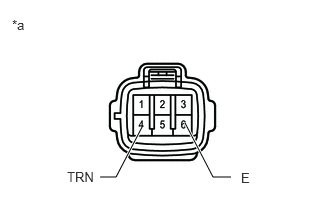
| *a | Component without harness connected
(Rear Combination Light Assembly LH) |
Disconnect the rear combination light assembly LH connector.
Apply battery voltage to the rear combination light assembly LH and check that the light illuminates.
- OK:
Condition Specified Condition Battery positive (+) → Terminal 4 (TRN)
Battery negative (-) → Terminal 6 (E)Turn signal light illuminates
- Result:
Proceed to OK NG
OK
NG
Disconnect the e1 rear combination light socket and wire sub-assembly LH connector.
Disconnect the N23 combination meter assembly connector.
Measure the resistance according to the value(s) in the table below.
- Standard Resistance:
Tester Connection Condition Specified Condition e1-4 (TRN) - N23-5 (TRNL) Always Below 1 Ω e1-6 (E) - Body ground Always Below 1 Ω
- Result:
Proceed to OK NG
OK
NG
| *a | Component without harness connected
(Rear Combination Light Socket and Wire Sub-assembly LH) |
Disconnect the rear combination light socket and wire sub-assembly LH connector.
Apply battery voltage to the rear combination light socket and wire sub-assembly LH and check that the light illuminates.
- OK:
Condition Specified Condition Battery positive (+) → Terminal 4 (TRN)
Battery negative (-) → Terminal 6 (E)Turn signal light illuminates
- Result:
Proceed to OK NG
OK
NG
Check vehicle condition.
- Result:
Result Proceed to for TAW Made A except TAW Made B
A
B
Disconnect the g1 rear combination light assembly RH connector.
Disconnect the N23 combination meter assembly connector.
Measure the resistance according to the value(s) in the table below.
- Standard Resistance:
Tester Connection Condition Specified Condition g1-4 (TRN) - N23-6 (TRNR) Always Below 1 Ω g1-6 (E) - Body ground Always Below 1 Ω
- Result:
Proceed to OK NG
OK
NG
| *a | Component without harness connected
(Rear Combination Light Assembly RH) |
Disconnect the rear combination light assembly RH connector.
Apply battery voltage to the rear combination light assembly RH and check that the light illuminates.
- OK:
Condition Specified Condition Battery positive (+) → Terminal 4 (TRN)
Battery negative (-) → Terminal 6 (E)Turn signal light illuminates
- Result:
Proceed to OK NG
OK
NG
Disconnect the g1 rear combination light socket and wire sub-assembly RH connector.
Disconnect the N23 combination meter assembly connector.
Measure the resistance according to the value(s) in the table below.
- Standard Resistance:
Tester Connection Condition Specified Condition g1-4 (TRN) - N23-6 (TRNR) Always Below 1 Ω g1-6 (E) - Body ground Always Below 1 Ω
- Result:
Proceed to OK NG
OK
NG
| *a | Component without harness connected
(Rear Combination Light Socket and Wire Sub-assembly RH) |
Disconnect the rear combination light socket and wire sub-assembly RH connector.
Apply battery voltage to the rear combination light socket and wire sub-assembly RH and check that the light illuminates.
- OK:
Condition Specified Condition Battery positive (+) → Terminal 4 (TRN)
Battery negative (-) → Terminal 6 (E)Turn signal light illuminates
- Result:
Proceed to OK NG
OK
NG
Inspect the illumination of each turn signal light.
- Result:
Result Proceed to Front turn signal light LH and side turn signal light LH do not blink. A Front turn signal light RH and side turn signal light RH do not blink. B Front turn signal light LH does not blink. C Side turn signal light LH does not blink. D Front turn signal light RH does not blink. E Side turn signal light RH does not blink. F Rear turn signal light LH does not blink. G Rear turn signal light RH does not blink. H
A
B
C
D
E
F
G
H
Disconnect the N23 combination meter assembly connector.
Disconnect the A54 Headlight ECU Sub-assembly LH connector.
Measure the resistance according to the value(s) in the table below.
- Standard Resistance:
Tester Connection Condition Specified Condition N23-1 (LL) - A54-11 (TNS) Always Below 1 Ω
- Result:
Proceed to OK NG
OK
NG
Disconnect the N23 combination meter assembly connector.
Disconnect the A55 Headlight ECU Sub-assembly RH connector.
Measure the resistance according to the value(s) in the table below.
- Standard Resistance:
Tester Connection Condition Specified Condition N23-2 (LR) - A55-11 (TNS) Always Below 1 Ω
- Result:
Proceed to OK NG
OK
NG
Disconnect the N23 combination meter assembly connector.
Disconnect the A54 Headlight ECU Sub-assembly LH connector.
Measure the resistance according to the value(s) in the table below.
- Standard Resistance:
Tester Connection Condition Specified Condition N23-1 (LL) - A54-11 (TNS) Always Below 1 Ω
- Result:
Proceed to OK NG
OK
NG
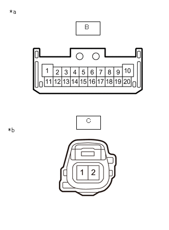
| *a | Component without harness connected
(to Headlight ECU Sub-assembly LH) |
| *b | Component without harness connected
(to Front Turn Signal Light Socket LH) |
Remove the headlight unit assembly LH.
Measure the resistance according to the value(s) in the table below.
- Standard Resistance:
Tester Connection Condition Specified Condition B-20 - C-1 Always Below 1 Ω B-13 - C-2 Always Below 1 Ω
- Result:
Proceed to OK NG
OK
NG
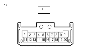
| *a | Component without harness connected
(to Headlight ECU Sub-assembly LH) |
Remove the headlight ECU sub-assembly LH.
Apply battery voltage to the headlight unit assembly LH and check that the light illuminates.
- OK:
Condition Specified Condition Battery positive (+) → B-20
Battery negative (-) → B-13Turn signal light illuminates
- Result:
Proceed to OK NG
OK
NG
Check vehicle condition.
- Result:
Result Proceed to w/ Panoramic View Monitor System A w/o Panoramic View Monitor System B
A
B
Remove the outer rear view mirror assembly LH.
Inspect the outer rear view mirror assembly LH.
- Result:
Proceed to OK NG
OK
NG
Remove the side turn signal light assembly LH.
Inspect the side turn signal light assembly LH.
- Result:
Proceed to OK NG
OK
NG
Remove the outer rear view mirror assembly LH.
Inspect the outer rear view mirror assembly LH.
- Result:
Proceed to OK NG
OK
NG
Remove the side turn signal light assembly LH.
Inspect the side turn signal light assembly LH.
- Result:
Proceed to OK NG
OK
NG
Disconnect the N23 combination meter assembly connector.
Disconnect the A55 Headlight ECU Sub-assembly RH connector.
Measure the resistance according to the value(s) in the table below.
- Standard Resistance:
Tester Connection Condition Specified Condition N23-2 (LR) - A55-11 (TNS) Always Below 1 Ω
- Result:
Proceed to OK NG
OK
NG
| *a | Component without harness connected
(to Headlight ECU Sub-assembly RH) |
| *b | Component without harness connected
(to Front Turn Signal Light Socket RH) |
Remove the headlight unit assembly RH.
Measure the resistance according to the value(s) in the table below.
- Standard Resistance:
Tester Connection Condition Specified Condition B-20 - C-1 Always Below 1 Ω B-13 - C-2 Always Below 1 Ω
- Result:
Proceed to OK NG
OK
NG
| *a | Component without harness connected
(to Headlight ECU Sub-assembly RH) |
Remove the headlight ECU sub-assembly RH.
Apply battery voltage to the headlight unit assembly RH and check that the light illuminates.
- OK:
Condition Specified Condition Battery positive (+) → B-20
Battery negative (-) → B-13Turn signal light illuminates
- Result:
Proceed to OK NG
OK
NG
Check vehicle condition.
- Result:
Result Proceed to w/ Panoramic View Monitor System A w/o Panoramic View Monitor System B
A
B
Remove the outer rear view mirror assembly RH.
Inspect the outer rear view mirror assembly RH.
- Result:
Proceed to OK NG
OK
NG
Remove the side turn signal light assembly RH.
Inspect the side turn signal light assembly RH.
- Result:
Proceed to OK NG
OK
NG
Remove the outer rear view mirror assembly RH.
Inspect the outer rear view mirror assembly RH.
- Result:
Proceed to OK NG
OK
NG
Remove the side turn signal light assembly RH.
Inspect the side turn signal light assembly RH.
- Result:
Proceed to OK NG
OK
NG
Disconnect the e4 rear combination light socket and wire sub-assembly LH connector.
Disconnect the N23 combination meter assembly connector.
Measure the resistance according to the value(s) in the table below.
- Standard Resistance:
Tester Connection Condition Specified Condition e4-3 (TRN) - N23-5 (TRNL) Always Below 1 Ω e4-4 (E) - Body ground Always Below 1 Ω
- Result:
Proceed to OK NG
OK
NG
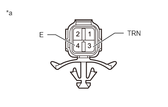
| *a | Component without harness connected
(Rear Combination Light Socket and Wire Sub-assembly LH) |
Disconnect the rear combination light socket and wire sub-assembly LH connector.
Apply battery voltage to the rear combination light socket and wire sub-assembly LH and check that the light illuminates.
- OK:
Condition Specified Condition Battery positive (+) → Terminal 3 (TRN)
Battery negative (-) → Terminal 4 (E)Turn signal light illuminates
- Result:
Proceed to OK NG
OK
NG
Disconnect the g2 rear combination light socket and wire sub-assembly RH connector.
Disconnect the N23 combination meter assembly connector.
Measure the resistance according to the value(s) in the table below.
- Standard Resistance:
Tester Connection Condition Specified Condition g2-3 (TRN) - N23-6 (TRNR) Always Below 1 Ω g2-4 (E) - Body ground Always Below 1 Ω
- Result:
Proceed to OK NG
OK
NG
| *a | Component without harness connected
(Rear Combination Light Socket and Wire Sub-assembly RH) |
Disconnect the rear combination light socket and wire sub-assembly RH connector.
Apply battery voltage to the rear combination light socket and wire sub-assembly RH and check that the light illuminates.
- OK:
Condition Specified Condition Battery positive (+) → Terminal 3 (TRN)
Battery negative (-) → Terminal 4 (E)Turn signal light illuminates
- Result:
Proceed to OK NG
OK
NG