MIRROR (EXT) OUTER REAR VIEW MIRROR INSPECTION
PROCEDURE

 87940
1.INSPECT OUTER REAR VIEW MIRROR ASSEMBLY LH (w/ Power Mirror Control System)
87940
1.INSPECT OUTER REAR VIEW MIRROR ASSEMBLY LH (w/ Power Mirror Control System)
w/ Blind Spot Monitor System:
Check the operation of the mirror surface.
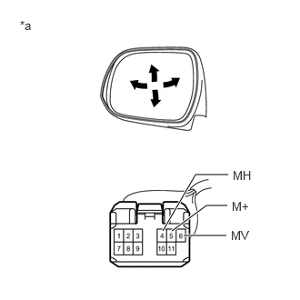
| *a | Component without harness connected
(Outer Rear View Mirror Assembly LH) |
Disconnect the outer rear view mirror assembly LH connector.
Apply battery voltage and check the operation of the mirror.
- OK:
Battery Connection Specified Condition Battery positive (+) → 6 (MV)
Battery negative (-) → 5 (M+)Turns upward Battery positive (+) → 5 (M+)
Battery negative (-) → 6 (MV)Turns downward Battery positive (+) → 4 (MH)
Battery negative (-) → 5 (M+)Turns left Battery positive (+) → 5 (M+)
Battery negative (-) → 4 (MH)Turns right
If the result is not as specified, replace the outer rear view mirror assembly LH.
Check the side turn signal light assembly LH.
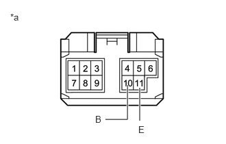
| *a | Component without harness connected
(Outer Rear View Mirror Assembly LH) |
Disconnect the outer rear view mirror assembly LH connector.
Apply battery voltage to the terminals of the connector, and check the illumination condition.
- OK:
Battery Connection Specified Condition Battery positive (+) → 10 (B)
Battery negative (-) → 11 (E)Side turn light illuminates
If the result is not as specified, inspect the side turn signal light assembly LH or replace the outer rear view mirror assembly LH.
Check the operation of the mirror heater.
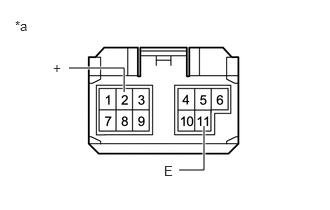
| *a | Component without harness connected
(Outer Rear View Mirror Assembly LH) |
Disconnect the outer rear view mirror assembly LH connector.
Measure the resistance according to the value(s) in the table below.
- Standard Resistance:
Tester Connection Condition Specified Condition 2 (+) - 11 (E) 25°C (75°F) 7.2 to 9.3 Ω
If the result is not as specified, replace the outer rear view mirror assembly LH.
Connect the cable from the positive (+) battery terminal to terminal 2 (+) and the negative (-) battery terminal to terminal 11 (-), and then check that the mirror becomes warm.
- HINT:
-
It takes a short time for the mirror to become warm.
- OK:
Mirror becomes warm.
If the result is not as specified, inspect the outer mirror LH or replace the outer rear view mirror assembly LH.
Check the operation of the blind spot monitor indicator.
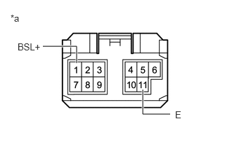
| *a | Component without harness connected
(Outer Rear View Mirror Assembly LH) |
Connect 4 new 1.5 V dry-cell batteries in series.
Measure the resistance according to the value(s) in the table below.
Apply 6 V dry-cell batteries to the terminals of the connector, and check the blind spot monitor indicator condition.
- OK:
Battery Connection Specified Condition Positive (+) end of the 6 V dry-cell battery → 1 (BSL+)
Negative (-) end of the 6 V dry-cell battery → 11 (E)Blind spot monitor indicator comes on
- NOTICE:
-
Do not apply a voltage of 6 V or higher.
If the result is not as specified, inspect the outer mirror LH or replace the outer rear view mirror assembly LH.
w/o Blind Spot Monitor System:
Check the operation of the mirror surface.
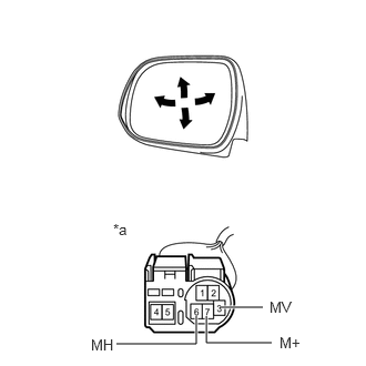
| *a | Component without harness connected
(Outer Rear View Mirror Assembly LH) |
Disconnect the outer rear view mirror assembly LH connector.
Apply battery voltage and check the operation of the mirror.
- OK:
Battery Connection Specified Condition Battery positive (+) → 3 (MV)
Battery negative (-) → 7 (M+)Turns upward Battery positive (+) → 7 (M+)
Battery negative (-) → 3 (MV)Turns downward Battery positive (+) → 6 (MH)
Battery negative (-) → 7 (M+)Turns left Battery positive (+) → 7 (M+)
Battery negative (-) → 6 (MH)Turns right
If the result is not as specified, replace the outer rear view mirror assembly LH.
Check the side turn signal light assembly LH.
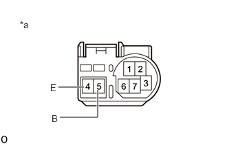
| *a | Component without harness connected
(Outer Rear View Mirror Assembly LH) |
Disconnect the outer rear view mirror assembly LH connector.
Apply battery voltage to the terminals of the connector, and check the illumination condition.
- OK:
Battery Connection Specified Condition Battery positive (+) → 5 (B)
Battery negative (-) → 4 (E)Side turn light illuminates
If the result is not as specified, inspect the side turn signal light assembly LH or replace the outer rear view mirror assembly LH.
87966
2.INSPECT OUTER MIRROR RETRACTOR LH (w/ Power Mirror Control System)
w/ Blind Spot Monitor System, w/o Panoramic View Monitor System:
Check the operation of the retractable mirror.
- NOTICE:
- ·
Disconnect and reconnect the battery between each mirror position check.
·The mirror position cannot be changed manually when the battery is connected. To change the mirror position manually, the battery must be disconnected first.
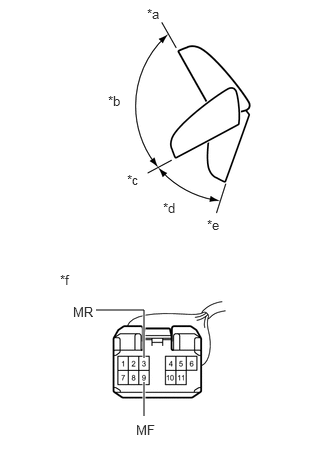
| *a | Forward position (A) |
| *b | (B) |
| *c | Driving position (C) |
| *d | (D) |
| *e | Retracted position (E) |
| *f | Component without harness connected
(Outer Rear View Mirror Assembly LH) |
Disconnect the outer rear view mirror assembly LH connector.
For each position: Disconnect the battery, set the mirror position by hand, connect the battery, and check the retractable mirror movement.
- OK:
Battery Connection Condition Specified Condition Battery positive (+) → 3 (MR)
Battery negative (-) → 9 (MF)Forward position (A) Moves from (A) to (E) Battery positive (+) → 9 (MF)
Battery negative (-) → 3 (MR)Forward position (A) Does not move Battery positive (+) → 3 (MR)
Battery negative (-) → 9 (MF)Position between forward position (A) and driving position (C) Moves from (B) to (E) Battery positive (+) → 9 (MF)
Battery negative (-) → 3 (MR)Position between forward position (A) and driving position (C) Moves from (B) to (A) Battery positive (+) → 3 (MR)
Battery negative (-) → 9 (MF)Driving position (C) Moves from (C) to (E) Battery positive (+) → 9 (MF)
Battery negative (-) → 3 (MR)Driving position (C) Does not move Battery positive (+) → 3 (MR)
Battery negative (-) → 9 (MF)Position between driving position (C) and retracted position (E) Moves from (D) to (E) Battery positive (+) → 9 (MF)
Battery negative (-) → 3 (MR)Position between driving position (C) and retracted position (E) Moves from (D) to (C) Battery positive (+) → 3 (MR)
Battery negative (-) → 9 (MF)Retracted position (E) Does not move Battery positive (+) → 9 (MF)
Battery negative (-) → 3 (MR)Retracted position (E) Moves from (E) to (C)
If the result is not as specified, replace the outer mirror retractor LH.
w/o Blind Spot Monitor System:
Check the operation of the retractable mirror.
- NOTICE:
- ·
Disconnect and reconnect the battery between each mirror position check.
·The mirror position cannot be changed manually when the battery is connected. To change the mirror position manually, the battery must be disconnected first.
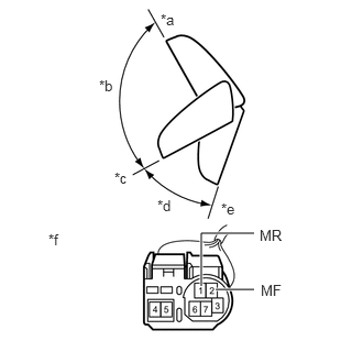
| *a | Forward position (A) |
| *b | (B) |
| *c | Driving position (C) |
| *d | (D) |
| *e | Retracted position (E) |
| *f | Component without harness connected
(Outer Rear View Mirror Assembly LH) |
Disconnect the outer rear view mirror assembly LH connector.
For each position: Disconnect the battery, set the mirror position by hand, connect the battery, and check the retractable mirror movement.
- OK:
Battery Connection Condition Specified Condition Battery positive (+) → 1 (MR)
Battery negative (-) → 2 (MF)Forward position (A) Moves from (A) to (E) Battery positive (+) → 2 (MF)
Battery negative (-) → 1 (MR)Forward position (A) Does not move Battery positive (+) → 1 (MR)
Battery negative (-) → 2 (MF)Position between forward position (A) and driving position (C) Moves from (B) to (E) Battery positive (+) → 2 (MF)
Battery negative (-) → 1 (MR)Position between forward position (A) and driving position (C) Moves from (B) to (A) Battery positive (+) → 1 (MR)
Battery negative (-) → 2 (MF)Driving position (C) Moves from (C) to (E) Battery positive (+) → 2 (MF)
Battery negative (-) → 1 (MR)Driving position (C) Does not move Battery positive (+) → 1 (MR)
Battery negative (-) → 2 (MF)Position between driving position (C) and retracted position (E) Moves from (D) to (E) Battery positive (+) → 2 (MF)
Battery negative (-) → 1 (MR)Position between driving position (C) and retracted position (E) Moves from (D) to (C) Battery positive (+) → 1 (MR)
Battery negative (-) → 2 (MF)Retracted position (E) Does not move Battery positive (+) → 2 (MF)
Battery negative (-) → 1 (MR)Retracted position (E) Moves from (E) to (C)
If the result is not as specified, replace the outer mirror retractor LH.
87940
3.INSPECT OUTER REAR VIEW MIRROR ASSEMBLY LH (w/ Panoramic View Monitor System)
Check the operation of the mirror surface.
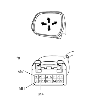
| *a | Component without harness connected
(Outer Rear View Mirror Assembly LH) |
Disconnect the outer rear view mirror assembly LH connector.
Apply battery voltage and check the operation of the mirror.
- OK:
Battery Connection Specified Condition Battery positive (+) → 1 (MV)
Battery negative (-) → 10 (M+)Turns upward Battery positive (+) → 10 (M+)
Battery negative (-) → 1 (MV)Turns downward Battery positive (+) → 9 (MH)
Battery negative (-) → 10 (M+)Turns left Battery positive (+) → 10 (M+)
Battery negative (-) → 9 (MH)Turns right
If the result is not as specified, replace the outer rear view mirror assembly LH.
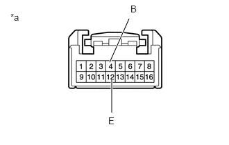
| *a | Component without harness connected
(Outer Rear View Mirror Assembly LH) |
Check the side turn signal light assembly LH.
Disconnect the outer rear view mirror assembly LH connector.
Apply battery voltage to the terminals of the connector, and check the illumination condition.
- OK:
Battery Connection Specified Condition Battery positive (+) → 4 (B)
Battery negative (-) → 12 (E)Side turn light illuminates
If the result is not as specified, inspect the side turn signal light assembly LH or replace the outer rear view mirror assembly LH.
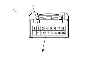
| *a | Component without harness connected
(Outer Rear View Mirror Assembly LH) |
Check the operation of the mirror heater.
Disconnect the outer rear view mirror assembly LH connector.
Measure the resistance according to the value(s) in the table below.
- Standard Resistance:
Tester Connection Condition Specified Condition 2 (+) - 12 (E) 25°C (75°F) 7.2 to 9.3 Ω
If the result is not as specified, replace the outer rear view mirror assembly LH.
Connect the cable from the positive (+) battery terminal to terminal 2 (+) and the negative (-) battery terminal to terminal 12 (E), and then check that the mirror becomes warm.
- HINT:
-
It takes a short time for the mirror to become warm.
- OK:
Mirror becomes warm.
If the result is not as specified, inspect the outer mirror LH or replace the outer rear view mirror assembly LH.
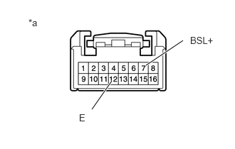
| *a | Component without harness connected
(Outer Rear View Mirror Assembly LH) |
Check the operation of the blind spot monitor indicator.
Connect 4 new 1.5 V dry-cell batteries in series.
Measure the resistance according to the value(s) in the table below.
Apply 6 V dry-cell batteries to the terminals of the connector, and check the blind spot monitor indicator condition.
- OK:
Battery Connection Specified Condition Positive (+) end of the 6 V dry-cell battery → 7 (BSL+)
Negative (-) end of the 6 V dry-cell battery → 12 (E)Blind spot monitor indicator comes on
- NOTICE:
-
Do not apply a voltage of 6 V or higher.
If the result is not as specified, inspect the outer mirror LH or replace the outer rear view mirror assembly LH.
Check the operation of the retractable mirror.
- NOTICE:
- ·
Disconnect and reconnect the battery between each mirror position check.
·The mirror position cannot be changed manually when the battery is connected. To change the mirror position manually, the battery must be disconnected first.
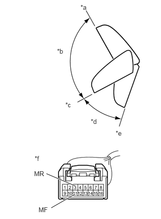
| *a | Forward position (A) |
| *b | (B) |
| *c | Driving position (C) |
| *d | (D) |
| *e | Retracted position (E) |
| *f | Component without harness connected
(Outer Rear View Mirror Assembly LH) |
Disconnect the outer rear view mirror assembly LH connector.
For each position: Disconnect the battery, set the mirror position by hand, connect the battery, and check the retractable mirror movement.
- OK:
Battery Connection Condition Specified Condition Battery positive (+) → 3 (MR)
Battery negative (-) → 11 (MF)Forward position (A) Moves from (A) to (E) Battery positive (+) → 11 (MF)
Battery negative (-) → 3 (MR)Forward position (A) Does not move Battery positive (+) → 3 (MR)
Battery negative (-) → 11 (MF)Position between forward position (A) and driving position (C) Moves from (B) to (E) Battery positive (+) → 11 (MF)
Battery negative (-) → 3 (MR)Position between forward position (A) and driving position (C) Moves from (B) to (A) Battery positive (+) → 3 (MR)
Battery negative (-) → 11 (MF)Driving position (C) Moves from (C) to (E) Battery positive (+) → 11 (MF)
Battery negative (-) → 3 (MR)Driving position (C) Does not move Battery positive (+) → 3 (MR)
Battery negative (-) → 11 (MF)Position between driving position (C) and retracted position (E) Moves from (D) to (E) Battery positive (+) → 11 (MF)
Battery negative (-) → 3 (MR)Position between driving position (C) and retracted position (E) Moves from (D) to (C) Battery positive (+) → 3 (MR)
Battery negative (-) → 11 (MF)Retracted position (E) Does not move Battery positive (+) → 11 (MF)
Battery negative (-) → 3 (MR)Retracted position (E) Moves from (E) to (C)
If the result is not as specified, replace the outer mirror retractor LH.
87910
4.INSPECT OUTER REAR VIEW MIRROR ASSEMBLY RH (w/ Power Mirror Control System)
w/ Blind Spot Monitor System:
Check the operation of the mirror surface.
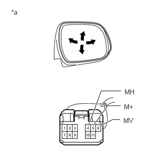
| *a | Component without harness connected
(Outer Rear View Mirror Assembly RH) |
Disconnect the outer rear view mirror assembly RH connector.
Apply battery voltage and check the operation of the mirror.
- OK:
Battery Connection Specified Condition Battery positive (+) → 6 (MV)
Battery negative (-) → 5 (M+)Turns upward Battery positive (+) → 5 (M+)
Battery negative (-) → 6 (MV)Turns downward Battery positive (+) → 4 (MH)
Battery negative (-) → 5 (M+)Turns left Battery positive (+) → 5 (M+)
Battery negative (-) → 4 (MH)Turns right
If the result is not as specified, replace the outer rear view mirror assembly RH.
Check the side turn signal light assembly RH.
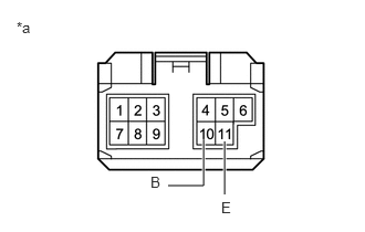
| *a | Component without harness connected
(Outer Rear View Mirror Assembly RH) |
Disconnect the outer rear view mirror assembly RH connector.
Apply battery voltage to the terminals of the connector, and check the illumination condition.
- OK:
Battery Connection Specified Condition Battery positive (+) → 10 (B)
Battery negative (-) → 11 (E)Side turn light illuminates
If the result is not as specified, inspect the side turn signal light assembly RH or replace the outer rear view mirror assembly RH.
Check the operation of the mirror heater.
| *a | Component without harness connected
(Outer Rear View Mirror Assembly RH) |
Disconnect the outer rear view mirror assembly RH connector.
Measure the resistance according to the value(s) in the table below.
- Standard Resistance:
Tester Connection Condition Specified Condition 2 (+) - 11 (E) 25°C (75°F) 7.2 to 9.3 Ω
Connect the cable from the positive (+) battery terminal to terminal 2 (+) and the negative (-) battery terminal to terminal 11 (-), and then check that the mirror becomes warm.
- HINT:
-
It takes a short time for the mirror to become warm.
- OK:
Mirror becomes warm.
If the result is not as specified, inspect the outer mirror RH or replace the outer rear view mirror assembly RH.
Check the operation of the blind spot monitor indicator.
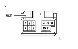
| *a | Component without harness connected
(Outer Rear View Mirror Assembly RH) |
Connect 4 new 1.5 V dry-cell batteries in series.
Measure the resistance according to the value(s) in the table below.
Apply 6 V dry-cell batteries to the terminals of the connector, and check the blind spot monitor indicator condition.
- OK:
Battery Connection Specified Condition Positive (+) end of the 6 V dry-cell battery → 1 (BSR+)
Negative (-) end of the 6 V dry-cell battery → 11 (E)Blind spot monitor indicator comes on
- NOTICE:
-
Do not apply a voltage of 6 V or higher.
If the result is not as specified, inspect the outer mirror RH or replace the outer rear view mirror assembly RH.
w/o Blind Spot Monitor System:
Check the operation of the mirror surface.
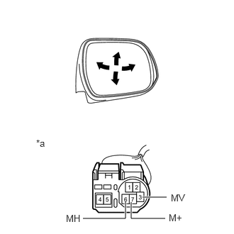
| *a | Component without harness connected
(Outer Rear View Mirror Assembly RH) |
Disconnect the outer rear view mirror assembly RH connector.
Apply battery voltage and check the operation of the mirror.
- OK:
Battery Connection Specified Condition Battery positive (+) → 3 (MV)
Battery negative (-) → 7 (M+)Turns upward Battery positive (+) → 7 (M+)
Battery negative (-) → 3 (MV)Turns downward Battery positive (+) → 6 (MH)
Battery negative (-) → 7 (M+)Turns left Battery positive (+) → 7 (M+)
Battery negative (-) → 6 (MH)Turns right
If the result is not as specified, replace the outer rear view mirror assembly RH.
Check the side turn signal light assembly RH.
| *a | Component without harness connected
(Outer Rear View Mirror Assembly RH) |
Disconnect the outer rear view mirror assembly RH connector.
Apply battery voltage to the terminals of the connector, and check the illumination condition.
- OK:
Battery Connection Specified Condition Battery positive (+) → 5 (B)
Battery negative (-) → 4 (E)Side turn light illuminates
If the result is not as specified, inspect the side turn signal light assembly RH or replace the outer rear view mirror assembly RH.
87946
5.INSPECT OUTER MIRROR RETRACTOR RH (w/ Power Mirror Control System)
w/ Blind Spot Monitor System, w/o Panoramic View Monitor System:
Check the operation of the retractable mirror.
- NOTICE:
- ·
Disconnect and reconnect the battery between each mirror position check.
·The mirror position cannot be changed manually when the battery is connected. To change the mirror position manually, the battery must be disconnected first.
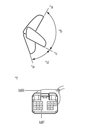
| *a | Forward position (A) |
| *b | (B) |
| *c | Driving position (C) |
| *d | (D) |
| *e | Retracted position (E) |
| *f | Component without harness connected
(Outer Rear View Mirror Assembly RH) |
Disconnect the outer rear view mirror assembly RH connector.
For each position: Disconnect the battery, set the mirror position by hand, connect the battery, and check the retractable mirror movement.
- OK:
Battery Connection Condition Specified Condition Battery positive (+) → 3 (MR)
Battery negative (-) → 9 (MF)Forward position (A) Moves from (A) to (E) Battery positive (+) → 9 (MF)
Battery negative (-) → 3 (MR)Forward position (A) Does not move Battery positive (+) → 3 (MR)
Battery negative (-) → 9 (MF)Position between forward position (A) and driving position (C) Moves from (B) to (E) Battery positive (+) → 9 (MF)
Battery negative (-) → 3 (MR)Position between forward position (A) and driving position (C) Moves from (B) to (A) Battery positive (+) → 3 (MR)
Battery negative (-) → 9 (MF)Driving position (C) Moves from (C) to (E) Battery positive (+) → 9 (MF)
Battery negative (-) → 3 (MR)Driving position (C) Does not move Battery positive (+) → 3 (MR)
Battery negative (-) → 9 (MF)Position between driving position (C) and retracted position (E) Moves from (D) to (E) Battery positive (+) → 9 (MF)
Battery negative (-) → 3 (MR)Position between driving position (C) and retracted position (E) Moves from (D) to (C) Battery positive (+) → 3 (MR)
Battery negative (-) → 9 (MF)Retracted position (E) Does not move Battery positive (+) → 9 (MF)
Battery negative (-) → 3 (MR)Retracted position (E) Moves from (E) to (C)
If the result is not as specified, replace the outer mirror retractor RH.
w/o Blind Spot Monitor System:
Check the operation of the retractable mirror.
- NOTICE:
- ·
Disconnect and reconnect the battery between each mirror position check.
·The mirror position cannot be changed manually when the battery is connected. To change the mirror position manually, the battery must be disconnected first.
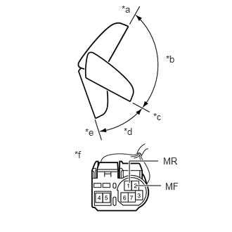
| *a | Forward position (A) |
| *b | (B) |
| *c | Driving position (C) |
| *d | (D) |
| *e | Retracted position (E) |
| *f | Component without harness connected
(Outer Rear View Mirror Assembly RH) |
Disconnect the outer rear view mirror assembly RH connector.
For each position: Disconnect the battery, set the mirror position by hand, connect the battery, and check the retractable mirror movement.
- OK:
Battery Connection Condition Specified Condition Battery positive (+) → 1 (MR)
Battery negative (-) → 2 (MF)Forward position (A) Moves from (A) to (E) Battery positive (+) → 2 (MF)
Battery negative (-) → 1 (MR)Forward position (A) Does not move Battery positive (+) → 1 (MR)
Battery negative (-) → 2 (MF)Position between forward position (A) and driving position (C) Moves from (B) to (E) Battery positive (+) → 2 (MF)
Battery negative (-) → 1 (MR)Position between forward position (A) and driving position (C) Moves from (B) to (A) Battery positive (+) → 1 (MR)
Battery negative (-) → 2 (MF)Driving position (C) Moves from (C) to (E) Battery positive (+) → 2 (MF)
Battery negative (-) → 1 (MR)Driving position (C) Does not move Battery positive (+) → 1 (MR)
Battery negative (-) → 2 (MF)Position between driving position (C) and retracted position (E) Moves from (D) to (E) Battery positive (+) → 2 (MF)
Battery negative (-) → 1 (MR)Position between driving position (C) and retracted position (E) Moves from (D) to (C) Battery positive (+) → 1 (MR)
Battery negative (-) → 2 (MF)Retracted position (E) Does not move Battery positive (+) → 2 (MF)
Battery negative (-) → 1 (MR)Retracted position (E) Moves from (E) to (C)
If the result is not as specified, replace the outer mirror retractor RH.
87910
6.INSPECT OUTER REAR VIEW MIRROR ASSEMBLY RH (w/ Panoramic View Monitor System)
Check the operation of the mirror surface.
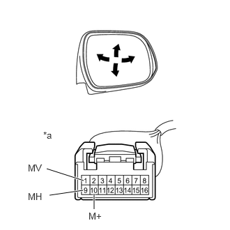
| *a | Component without harness connected
(Outer Rear View Mirror Assembly RH) |
Disconnect the outer rear view mirror assembly RH connector.
Apply battery voltage and check the operation of the mirror.
- OK:
Battery Connection Specified Condition Battery positive (+) → 1 (MV)
Battery negative (-) → 10 (M+)Turns upward Battery positive (+) → 10 (M+)
Battery negative (-) → 1 (MV)Turns downward Battery positive (+) → 9 (MH)
Battery negative (-) → 10 (M+)Turns left Battery positive (+) → 10 (M+)
Battery negative (-) → 9 (MH)Turns right
If the result is not as specified, replace the outer rear view mirror assembly RH.
| *a | Component without harness connected
(Outer Rear View Mirror Assembly RH) |
Check the side turn signal light assembly RH.
Disconnect the outer rear view mirror assembly RH connector.
Apply battery voltage to the terminals of the connector, and check the illumination condition.
- OK:
Battery Connection Specified Condition Battery positive (+) → 4 (B)
Battery negative (-) → 12 (E)Side turn light illuminates
If the result is not as specified, inspect the side turn signal light assembly RH or replace the outer rear view mirror assembly RH.
| *a | Component without harness connected
(Outer Rear View Mirror Assembly RH) |
Check the operation of the mirror heater.
Disconnect the outer rear view mirror assembly RH connector.
Measure the resistance according to the value(s) in the table below.
- Standard Resistance:
Tester Connection Condition Specified Condition 2 (+) - 12 (E) 25°C (75°F) 7.2 to 9.3 Ω
If the result is not as specified, replace the outer rear view mirror assembly RH.
Connect the cable from the positive (+) battery terminal to terminal 2 (+) and the negative (-) battery terminal to terminal 12 (E), and then check that the mirror becomes warm.
- HINT:
-
It takes a short time for the mirror to become warm.
- OK:
Mirror becomes warm.
If the result is not as specified, inspect the outer mirror RH or replace the outer rear view mirror assembly RH.
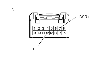
| *a | Component without harness connected
(Outer Rear View Mirror Assembly RH) |
Check the operation of the blind spot monitor indicator.
Connect 4 new 1.5 V dry-cell batteries in series.
Measure the resistance according to the value(s) in the table below.
Apply 6 V dry-cell batteries to the terminals of the connector, and check the blind spot monitor indicator condition.
- OK:
Battery Connection Specified Condition Positive (+) end of the 6 V dry-cell battery → 7 (BSR+)
Negative (-) end of the 6 V dry-cell battery → 12 (E)Blind spot monitor indicator comes on
- NOTICE:
-
Do not apply a voltage of 6 V or higher.
If the result is not as specified, inspect the outer mirror RH or replace the outer rear view mirror assembly RH.
Check the operation of the retractable mirror.
- NOTICE:
- ·
Disconnect and reconnect the battery between each mirror position check.
·The mirror position cannot be changed manually when the battery is connected. To change the mirror position manually, the battery must be disconnected first.
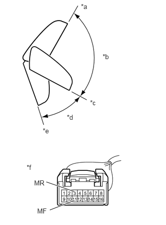
| *a | Forward position (A) |
| *b | (B) |
| *c | Driving position (C) |
| *d | (D) |
| *e | Retracted position (E) |
| *f | Component without harness connected
(Outer Rear View Mirror Assembly RH) |
Disconnect the outer rear view mirror assembly RH connector.
For each position: Disconnect the battery, set the mirror position by hand, connect the battery, and check the retractable mirror movement.
- OK:
Battery Connection Condition Specified Condition Battery positive (+) → 3 (MR)
Battery negative (-) → 11 (MF)Forward position (A) Moves from (A) to (E) Battery positive (+) → 11 (MF)
Battery negative (-) → 3 (MR)Forward position (A) Does not move Battery positive (+) → 3 (MR)
Battery negative (-) → 11 (MF)Position between forward position (A) and driving position (C) Moves from (B) to (E) Battery positive (+) → 11 (MF)
Battery negative (-) → 3 (MR)Position between forward position (A) and driving position (C) Moves from (B) to (A) Battery positive (+) → 3 (MR)
Battery negative (-) → 11 (MF)Driving position (C) Moves from (C) to (E) Battery positive (+) → 11 (MF)
Battery negative (-) → 3 (MR)Driving position (C) Does not move Battery positive (+) → 3 (MR)
Battery negative (-) → 11 (MF)Position between driving position (C) and retracted position (E) Moves from (D) to (E) Battery positive (+) → 11 (MF)
Battery negative (-) → 3 (MR)Position between driving position (C) and retracted position (E) Moves from (D) to (C) Battery positive (+) → 3 (MR)
Battery negative (-) → 11 (MF)Retracted position (E) Does not move Battery positive (+) → 11 (MF)
Battery negative (-) → 3 (MR)Retracted position (E) Moves from (E) to (C)
If the result is not as specified, replace the outer mirror retractor RH.