LIGHTING (EXT) HEADLIGHT ASSEMBLY(for LED Headlight) DISASSEMBLY
CAUTION / NOTICE / HINT
- NOTICE:
- ·
Handle components indoors as much as possible to prevent foreign matter from entering and adhering to headlight assembly components.
·Do not reuse parts which have reduced fastening ability due to thread damage.
·Do not touch the inner surface of the lens and metallic surfaces as much as possible, or they may become dirty.
·Do not allow metallic surfaces to become dirty, as such surfaces become damaged even if they are only lightly wiped with a soft cloth.
·When installing components, make sure that the wire harness is not pinched or pulled.
·Do not use solvent to clean components. Only clean them with a dry cloth.
- HINT:
- ·
Use the same procedure for the RH and LH sides.
·The procedure listed below is for the LH side.
PROCEDURE

 81510C
1.REMOVE FRONT TURN SIGNAL LIGHT BULB
81510C
1.REMOVE FRONT TURN SIGNAL LIGHT BULB
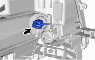
Disconnect the connector.
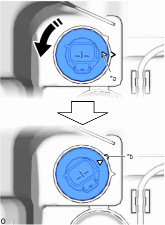
| *a | Matchmark |
| *b | Unlock Position Mark |

|
Turn in this Direction |
Turn the bulb socket counterclockwise until the matchmark is aligned with the unlock position mark and remove it.
|
|
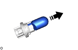
Remove in this Direction |
Remove the front turn signal light bulb from the bulb socket.
81194A
2.REMOVE HEADLIGHT PROTECTOR LH
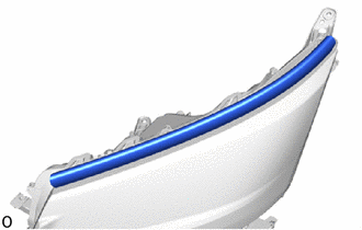
Remove the headlight protector LH.
- NOTICE:
-
The headlight protector LH must not be reused.
81056A
3.REMOVE HEADLIGHT ECU SUB-ASSEMBLY LH
81134
4.REMOVE HEADLIGHT GASKET
81158
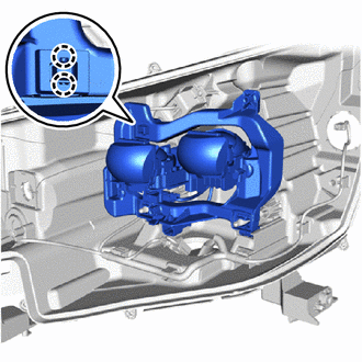
5.REMOVE HEADLIGHT BRACKET LH
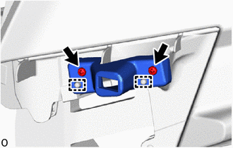
Remove the 2 screws.
Detach the guide and remove the headlight bracket LH.
8110B
6.REMOVE HEADLIGHT LENS SUB-ASSEMBLY LH
- NOTICE:
- ·
Perform work using clean rubber gloves.
·Do not touch the inner surface of the lens and metallic surfaces as much as possible, or they may become dirty.
·Do not allow metallic surfaces to become dirty, as such surfaces become damaged even if they are only lightly wiped with a soft cloth.
·Do not use solvent to clean components. Only clean them with a dry cloth.

| *a | Matchmark |
| *b | Unlock Position Mark |
|
|
Turn in this Direction |
Turn the headlight back cover counterclockwise until the matchmark is aligned with the unlock position mark and remove it.
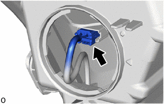
Disconnect the connector.
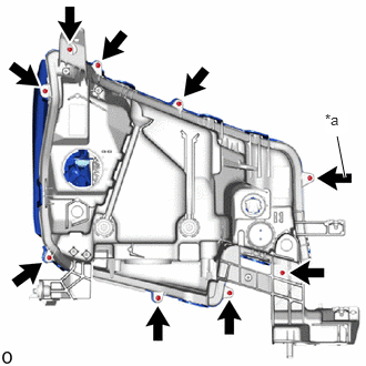
| *a | "TORX" Screw |
Remove the 8 screws.
Using a T20H "TORX" driver, remove the "TORX" screw.
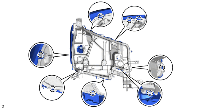
Detach the claw.
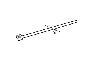
| *a | 7.6 mm (0.299 in.) |
Prepare a cable tie with a width of 7.6 mm (0.299 in.).
- HINT:
-
Cable ties with a narrow width (2.5 mm (0.0984 in.) etc.) are difficult to pull out through the headlight lens gasket.
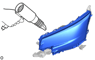
Using a dryer, warm the area around the cable tie insertion area on the headlight lens gasket at the rear of the headlight housing.
- NOTICE:
-
If the headlight is heated unevenly, it will deform or melt.
- HINT:
-
The headlight lens gasket becomes soft and easy to pull through when warmed.
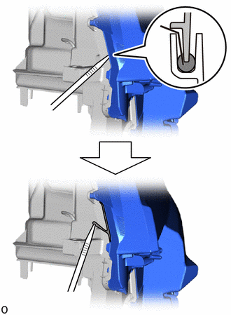

|
Cable Tie |

|
Headlight Lens Gasket |

|
Headlight Lens Sub-assembly LH |

|
Headlight Housing |
Insert a cable tie between the headlight lens sub-assembly LH and headlight housing and pull out the headlight lens gasket as shown in the illustration.
- NOTICE:
-
Do not damage the groove in the headlight housing or the surface of the headlight lens sub-assembly LH.
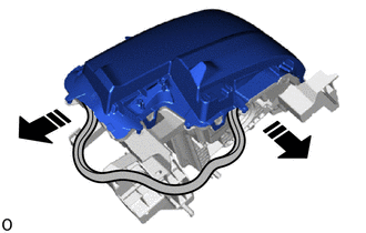
|
|
Remove in this Direction |
Pull out the headlight lens gasket in the direction indicated by the arrow until the headlight lens sub-assembly LH and headlight housing adhesion is gone.
- HINT:
-
If the headlight lens gasket is disconnected while being pulled out, insert a cable tie between the headlight lens sub-assembly LH and headlight housing and pull out the headlight lens gasket again.
Lift up the headlight lens sub-assembly LH directly upwards and remove it.
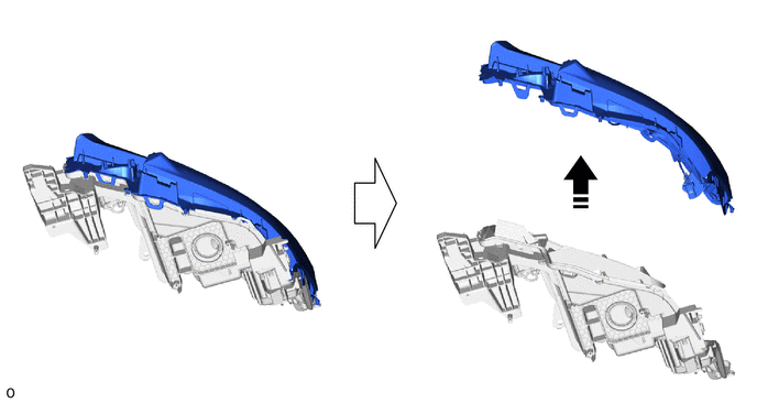
|
|
Remove in this Direction | - | - |
81132B
7.REMOVE HEADLIGHT LENS GASKET
- NOTICE:
- ·
The headlight lens gasket must not be reused.
·Perform work using clean rubber gloves.
·Do not touch the inner surface of the lens and metallic surfaces as much as possible, or they may become dirty.
·Do not allow metallic surfaces to become dirty, as such surfaces become damaged even if they are only lightly wiped with a soft cloth.
·If there are fingerprints on the inner surface of the lens, lightly wipe with a soft cloth.
·Do not use solvent to clean components. Only clean them with a dry cloth.
Remove the remaining headlight lens gasket from the headlight lens and headlight housing.
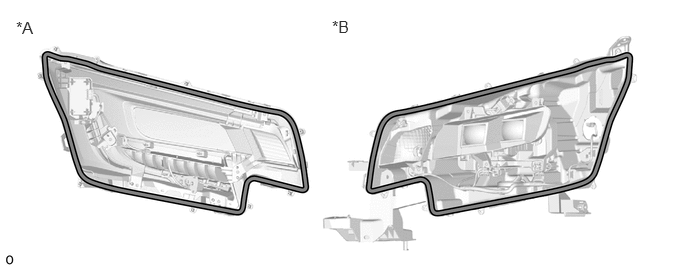
| *A | Headlight Lens Side | *B | Headlight Housing Side |
|
|
Headlight Lens Gasket | - | - |
81160
8.REMOVE HEADLIGHT SUB-ASSEMBLY LH
- NOTICE:
- ·
Prevention of static electricity is required during this procedure.
·Use static electricity countermeasures SST (desktop antistatic mat set) and observe all precautions to prevent damage to the system by electrostatic discharge (ESD).
·Perform work using clean rubber gloves.
·Do not touch the headlight sub-assembly LH with bare hands.
·Do not allow metallic surfaces to become dirty, as such surfaces become damaged even if they are only lightly wiped with a soft cloth.
·If there are fingerprints on the inner surface of the lens, lightly wipe with a soft cloth.
·Do not use solvent to clean components. Only clean them with a dry cloth.
- SST
- 09890-47010 (09891-04020, 09891-04010, 09891-04030, 09891-04040)
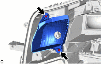
Remove the 2 screws and turn signal reflector.
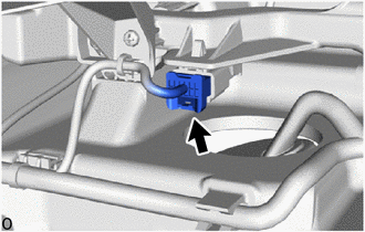
Disconnect the connector.
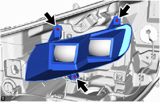
Remove the 3 screws.
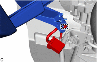
Detach the clamp and remove the headlight unit bezel.
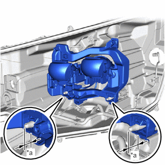
| *a | Protrusion Amount Measurement Area |
Using a vernier caliper, measure and record the dimensions of the protrusion of the aiming screws for beam axis vertical and horizontal adjustments.
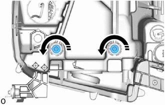
|
|
Loosen in this Direction |
Hold the headlight sub-assembly LH with one hand to prevent it from tipping over and loosen the aiming screws for beam axis vertical and horizontal adjustments counterclockwise by 10 turns.
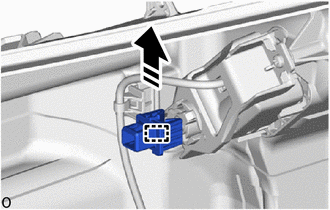
Detach the claw and disconnect the headlight sub-assembly LH from the pivot collar.
|
|
Loosen in this Direction |
Hold the headlight sub-assembly LH with one hand to prevent it from tipping over and loosen the aiming screws for beam axis vertical and horizontal adjustments counterclockwise until the headlight sub-assembly LH is disconnected.
|
|
Remove in this Direction. |
Detach the guide and remove the pivot collar as shown in the illustration.
Install the removed pivot collar to the headlight sub-assembly LH.
85662
9.REMOVE HEADLIGHT LEVELING MOTOR LH
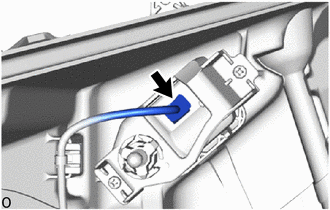
Disconnect the connector.
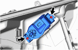
Remove the 2 screws and headlight leveling motor LH.