MIRROR (EXT) OUTER REAR VIEW MIRROR DISASSEMBLY
CAUTION / NOTICE / HINT
- HINT:
- ·
Use the same procedure for the RH and LH sides.
·The procedure listed below is for the LH side.
PROCEDURE

 87961
1.REMOVE OUTER MIRROR LH
87961
1.REMOVE OUTER MIRROR LH
87945
2.REMOVE OUTER MIRROR COVER LH
81740
3.REMOVE SIDE TURN SIGNAL LIGHT ASSEMBLY LH (w/ Side Turn Signal Light)
Remove the cover body.
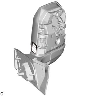

|
Protective Tape |
Apply protective tape to the areas shown in the illustration.
w/o Panoramic View Monitor System:
Remove the 2 screws.
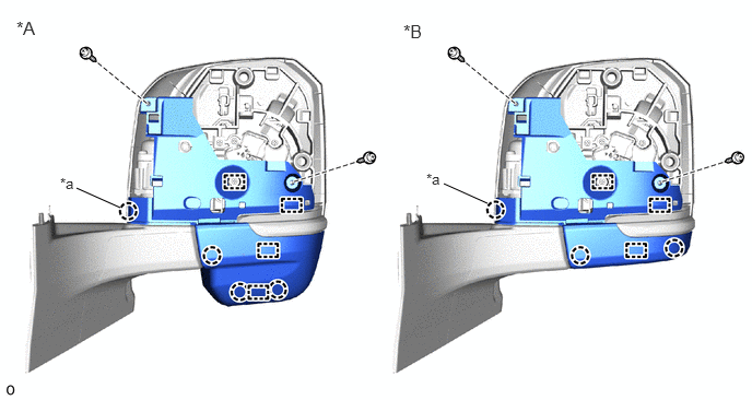
| *A | w/ Sub Mirror | *B | w/o Sub Mirror |
| *a | Claw A | - | - |
Detach the claw and guide.
- HINT:
-
Do not detach claw A.
w/ Panoramic View Monitor System:
Remove the 2 screws.
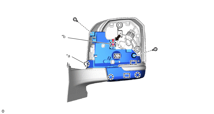
| *a | Claw A | *b | Wire Harness Clamp |
Detach the wire harness clamp and disconnect the connector.
Detach the claw and guide.
- HINT:
-
Do not detach claw A.
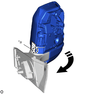
| *a | Claw A |

|
Move in this Direction |
Move the outer rear view mirror assembly LH to the forward position.
- NOTICE:
-
Do not damage the cover and claw A when moving the part.
|
|
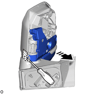
Remove in this Direction |
|
|
Protective Tape |
Using a thin-bladed screwdriver, detach the claw to remove the cover body.
- HINT:
-
Tape the thin-bladed screwdriver tip before use.
w/ Panoramic View Monitor System:
Remove the side television camera assembly LH.
|
|
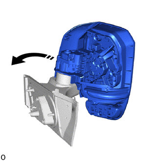
Move in this Direction |
Move the outer rear view mirror assembly LH to the driving position.
|
|
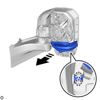
Remove in this Direction |
Detach the claw to remove the side turn signal light assembly LH.
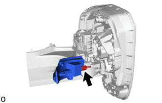
Disconnect the connector.
87966
4.REMOVE OUTER MIRROR RETRACTOR LH (w/o Panoramic View Monitor System, w/ Power Retract Mirror)
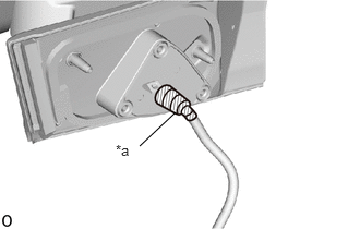
| *a | Vinyl Tape |
Remove the vinyl tape.
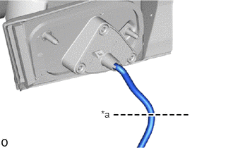
| *a | Cut |
Cut the wire harness sub-assembly at the position shown in the illustration.
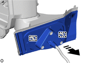
|
|
Remove in this Direction |
Detach the guide and remove the gasket sub-assembly as shown in the illustration.
- NOTICE:
-
Make sure to replace the gasket sub-assembly with a new one.
Remove the lower cover base.
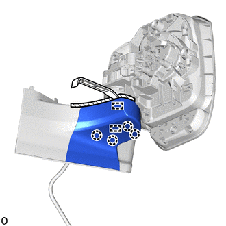
|
|
Protective Tape |
Apply protective tape to the areas shown in the illustration.
Using a moulding remover A, detach the claw and guide.
- NOTICE:
-
Make sure to replace the lower cover base with a new one.
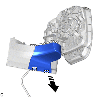
|
|
Remove in this Direction |
Detach the guide and remove the lower cover base in the removal direction.
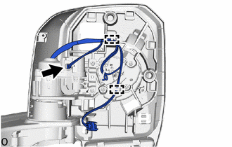
Disconnect the connector and detach the guide.
Remove the actuator sub-assembly.
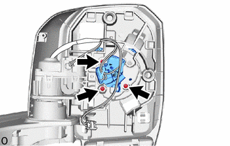
Remove the 3 screws and actuator sub-assembly.
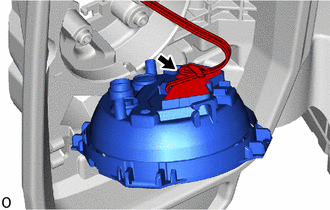
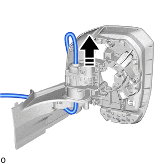
Disconnect the wire harness connector.
|
|
Remove in this Direction |
Pull the wire harness sub-assembly through the frame sub-assembly as shown in the illustration to remove the wire harness sub-assembly.
- NOTICE:
-
Make sure to replace the wire harness sub-assembly with a new one.
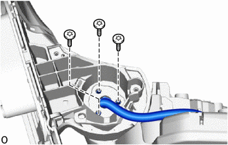
Using a T25 "TORX" socket wrench, remove the 3 "TORX" screws and base sub-assembly.
- NOTICE:
-
Make sure to replace the "TORX" screw with a new one.
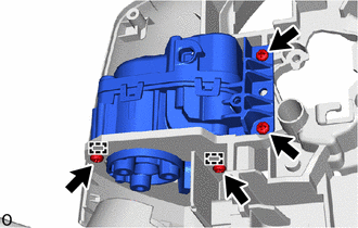
Remove the 4 screws.
Detach the guide and remove the frame sub-assembly.
- NOTICE:
-
Make sure to replace the frame sub-assembly with a new one.