INTERIOR PANELS / TRIM ROOF HEADLINING(for Wagon) INSTALLATION
CAUTION / NOTICE / HINT
- HINT:
- ·
Use the same procedure for RHD and LHD vehicles.
·The procedure listed below is for LHD vehicles.
·A bolt without a torque specification is shown in the standard bolt chart.
PROCEDURE

 1.INSTALL ROOF HEADLINING ASSEMBLY
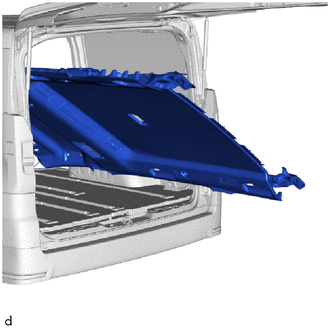
Tilt the roof headlining assembly vertically and carry it onto the vehicle through the back door.
- NOTICE:
- ·
Installation of the roof headlining assembly must be performed by multiple people to prevent deformation of the roof headlining assembly.
·Check that the corners of the roof headlining are not folded, twisted or otherwise deformed and that none of the mounted parts have fallen off.
·Make sure that the roof headlining does not get caught on anything as it may become bent or damaged.
·Do not damage the roof headlining or vehicle interior.
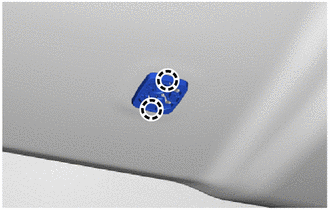
Attach the claw to install the visor holder base.
- HINT:
-
Use the same procedure for the opposite side.
w/ Rear Cooler:
Attach the fastener and hook.
Install the roof headlining assembly with the 2 clips and 2 plates.
- HINT:
-
The clips indicated by the arrow have plates between the roof headlining assembly and body. Be careful not to let them fall.
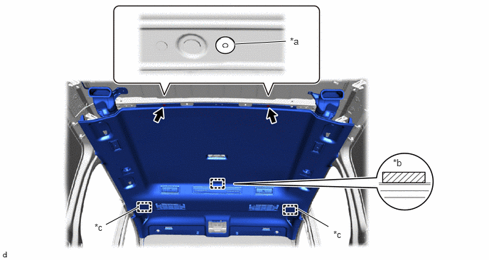
| *a | Plate | *b | Fastener |
| *c | Hook | - | - |
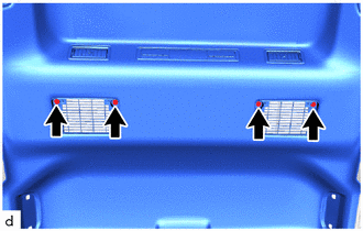
Install the 4 bolts.
w/ Rear Air Conditioning System:
Attach the fastener and hook.
Install the roof headlining assembly with the 2 clips and 2 plates.
- HINT:
-
The clips indicated by the arrow have plates between the roof headlining assembly and body. Be careful not to let them fall.
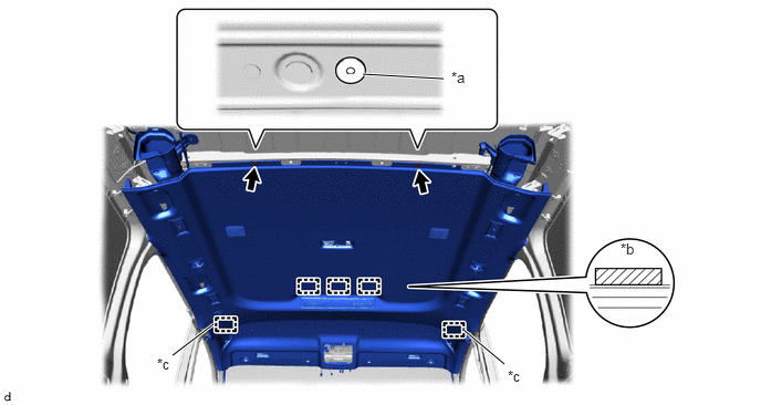
| *a | Plate | *b | Fastener |
| *c | Hook | - | - |
for Rear Roof RH Side, w/ Digital Inner Mirror:
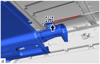
Attach the clamp and connect the connector.
for Rear Roof LH Side:
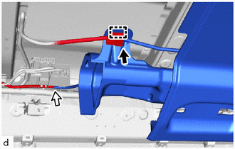

|
Connector |

|
Washer Hose |
Connect the connector and attach the clamp.
Connect the washer hose.
for Front Pillar LH Side:
w/ Curtain Shield Airbag:
Remove the protective cover installed to the front pillar LH.
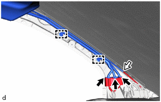
|
|
Connector |
|
|
Washer Hose |
Connect the washer hose.
Attach the wire harness clamp.
Connect the 3 connectors.
w/ Curtain Shield Airbag:
Install the protective cover to the front pillar LH.
for Windshield Glass Side:
Connect each connector.
67872A
2.INSTALL NO. 1 SLIDE DOOR WEATHERSTRIP LH
- HINT:
-
Use the same procedure described for the RH side.
67871E
3.INSTALL NO. 1 SLIDE DOOR WEATHERSTRIP RH
53989A
4.INSTALL AIR INTAKE NET
74348
5.INSTALL VISOR HOLDER
74320
6.INSTALL VISOR ASSEMBLY LH
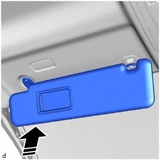

|
Install in this Direction |
Set the visor assembly LH into place by aligning it upward with the screw fastening hole.
- NOTICE:
-
Hold the visor assembly with one hand so that it does not drop.
Connect the visor assembly LH to the visor holder LH to set it into place.
74310
7.INSTALL VISOR ASSEMBLY RH
- HINT:
-
Use the same procedure described for the LH side.
74318
8.INSTALL VISOR BRACKET COVER LH
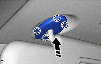
|
|
Install in this Direction |
Attach the claw to install the visor bracket cover LH as shown in the illustration.
74317
9.INSTALL VISOR BRACKET COVER RH
- HINT:
-
Use the same procedure described for the LH side.
10.INSTALL ASSIST GRIP ASSEMBLY
86466D
11.INSTALL NO. 1 FORWARD RECOGNITION COVER (w/ Pre-collision System)
81260A
12.INSTALL MAP LIGHT ASSEMBLY
87834
13.INSTALL INNER REAR VIEW MIRROR STAY HOLDER COVER
w/ Digital Inner Mirror:
89943
14.INSTALL RAIN SENSOR COVER
15.INSTALL REAR ROOF HEADLINING ASSEMBLY
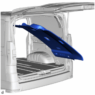
Tilt the rear roof headlining assembly vertically and carry it onto the vehicle through the back door.
- NOTICE:
- ·
Installation of the rear roof headlining assembly must be performed by multiple people to prevent deformation of the roof headlining assembly.
·Check that the corners of the roof headlining are not folded, twisted or otherwise deformed and that none of the mounted parts have fallen off.
·Make sure that the roof headlining does not get caught on anything as it may become bent or damaged.
·Do not damage the roof headlining or vehicle interior.
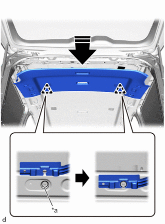
| *a | Clip |
|
|
Install in this Direction |
Align the rear roof headlining assembly with the clip on the vehicle side in the direction of the arrow shown in the illustration.
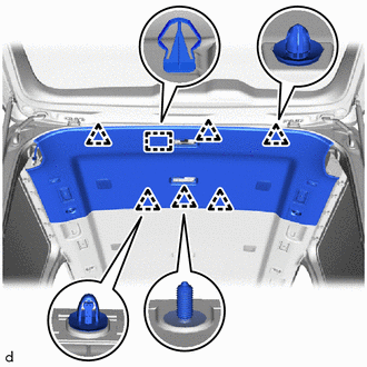
Attach the guide.
Attach the clip to install the rear roof headlining assembly.
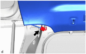
Connect the connector.
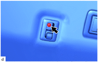
Install the screw.
- HINT:
-
Use the same procedure for the opposite side.
81240
16.INSTALL NO. 1 ROOM LIGHT ASSEMBLY
81240D
17.INSTALL NO. 2 ROOM LIGHT ASSEMBLY
- HINT:
-
Use the same procedure described for the No. 1 room light assembly.
62460A
18.INSTALL REAR ROOF SIDE RAIL GARNISH ASSEMBLY LH
w/ Rear Sunshade:
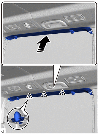
|
|
Install in this Direction |
Attach the clip to install the rear roof side rail garnish assembly LH as shown in the illustration.
- HINT:
-
Install the sunshade hook together with the rear roof side garnish assembly LH.
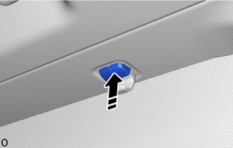
|
|
Install in this Direction |
Attach the pin in the direction indicated by the arrow shown in the illustration.
- HINT:
-
Use the same procedure described for the other side.
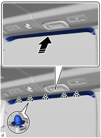
|
|
Install in this Direction |
w/o Rear Sunshade:
Attach the clip to install the rear roof side rail garnish assembly LH as shown in the illustration.
62450A
19.INSTALL REAR ROOF SIDE RAIL GARNISH ASSEMBLY RH
- HINT:
-
Use the same procedure described for the LH side.
62472D
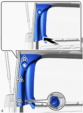
20.INSTALL REAR UPPER PILLAR GARNISH LH
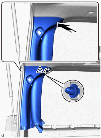
|
|
Install in this Direction |
Attach the clip and claw as shown in the illustration.
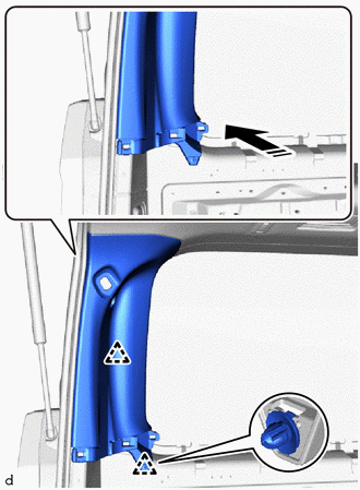
|
|
Install in this Direction |
Attach the clip as shown in the illustration.
|
|
Install in this Direction |
Attach the clip as shown in the illustration to install the rear upper pillar garnish LH.
62471D
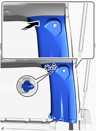
21.INSTALL REAR UPPER PILLAR GARNISH RH
for Rear Cooler:
- HINT:
-
Use the same procedure described for the LH side.
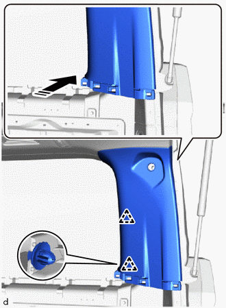
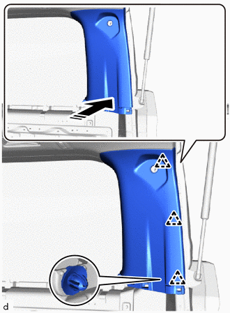
for Rear Air Conditioning System:
for Rear Cooler:
|
|
Install in this Direction |
Attach the clip and claw as shown in the illustration.
|
|
Install in this Direction |
Attach the clip as shown in the illustration.
|
|
Install in this Direction |
Attach the clip as shown in the illustration to install the rear upper pillar garnish LH.
72681E
22.INSTALL REAR SEAT HOOK (w/ Seat Hook)
62639A
23.INSTALL QUARTER PILLAR GARNISH LH
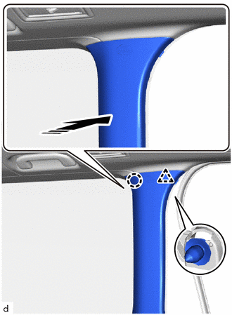
|
|
Install in this Direction |
Attach the claw and clip as shown in the illustration.
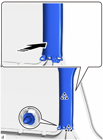
|
|
Install in this Direction |
Attach the clip as shown in the illustration to install the quarter pillar garnish LH.
62638A
24.INSTALL QUARTER PILLAR GARNISH RH
- HINT:
-
Use the same procedure described for the LH side.
62520B
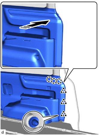
25.INSTALL QUARTER TRIM PANEL ASSEMBLY LH
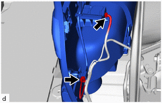
Connect the 2 connectors.
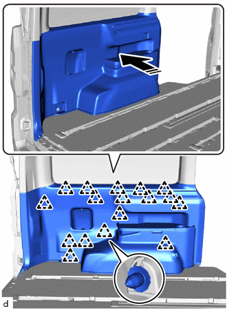
|
|
Install in this Direction |
Attach the clip as shown in the illustration.
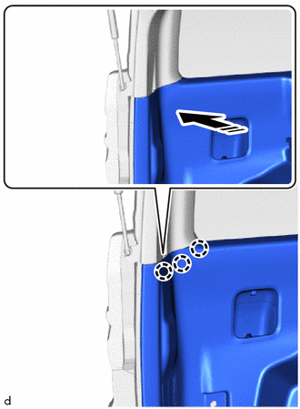
|
|
Install in this Direction |
Attach the clip and claw as shown in the illustration.
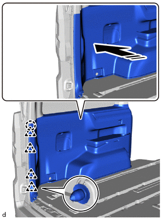
|
|
Install in this Direction |
Attach the claw as shown in the illustration.
|
|
Install in this Direction |
Attach the clip and claw as shown in the illustration to install the quarter trim panel assembly LH.
62510M
26.INSTALL QUARTER TRIM PANEL ASSEMBLY RH
for Rear Cooler:
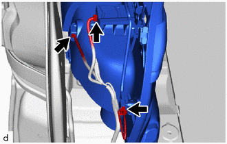
Connect each connector.
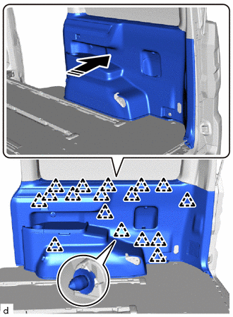
|
|
Install in this Direction |
Attach the clip as shown in the illustration.
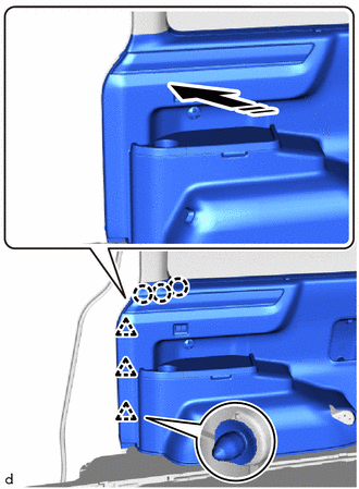
|
|
Install in this Direction |
Attach the clip and claw as shown in the illustration.
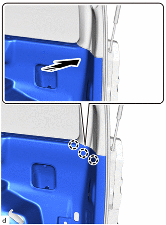
|
|
Install in this Direction |
Attach the claw as shown in the illustration.
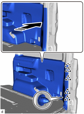
|
|
Install in this Direction |
Attach the clip and claw as shown in the illustration to install the quarter trim panel assembly RH.
for Rear Air Conditioning System:
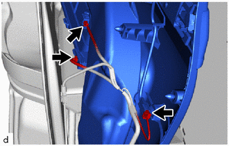
Connect each connector.
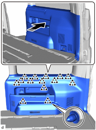
|
|
Install in this Direction |
Attach the clip as shown in the illustration.
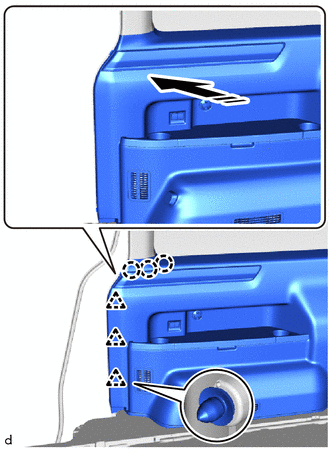
|
|
Install in this Direction |
Attach the clip and claw as shown in the illustration.
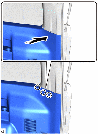
|
|
Install in this Direction |
Attach the claw as shown in the illustration.
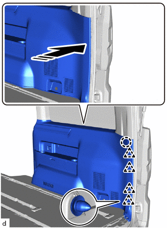
|
|
Install in this Direction |
Attach the clip and claw as shown in the illustration to install the quarter trim panel assembly RH.
67872A
27.INSTALL NO. 1 SLIDE DOOR WEATHERSTRIP LH
- HINT:
-
Use the same procedure described for the RH side.
67871E
28.INSTALL NO. 1 SLIDE DOOR WEATHERSTRIP RH
73370E
29.INSTALL REAR SEAT OUTER BELT ASSEMBLY LH (w/ Seat Belt)
73360D
30.INSTALL REAR SEAT OUTER BELT ASSEMBLY RH (w/ Seat Belt)
- HINT:
-
Use the same procedure described for the LH side.
73233D
31.INSTALL OUTER LAP BELT ANCHOR COVER (w/ Seat Belt)
67935
32.INSTALL BACK DOOR SCUFF PLATE
62412
33.INSTALL CENTER PILLAR GARNISH LH
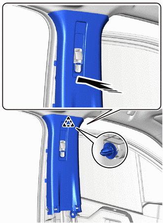
|
|
Install in this Direction |
Attach the clip as shown in the illustration.
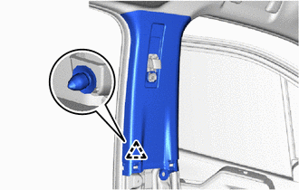
Attach the clip to install the center pillar garnish LH.
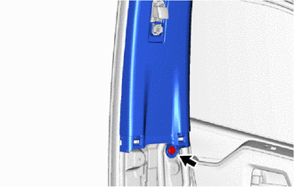
Install the clip.
62411
34.INSTALL CENTER PILLAR GARNISH RH
- HINT:
-
Use the same procedure described for the LH side.
62414A
35.INSTALL LOWER CENTER PILLAR GARNISH LH
- HINT:
-
Use the same procedure described for the RH side.
62413A
36.INSTALL LOWER CENTER PILLAR GARNISH RH
74680
37.INSTALL PILLAR ASSIST GRIP ASSEMBLY B
- HINT:
-
Use the same procedure for both pillar assist grip assemblies B.
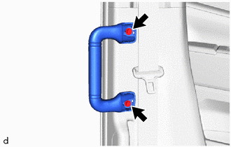
Install the pillar assist grip assembly B with the 2 bolts.
74617A
38.INSTALL ASSIST GRIP PLUG
- HINT:
-
Use the same procedure for both assist grip plugs.
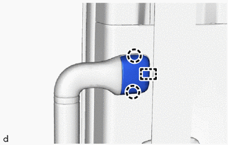
Attach the claw and guide to install the assist grip plug.
67872A
39.INSTALL NO. 1 SLIDE DOOR WEATHERSTRIP LH
- HINT:
-
Use the same procedure described for the RH side.
67871E
40.INSTALL NO. 1 SLIDE DOOR WEATHERSTRIP RH
67918D
41.INSTALL REAR DOOR SCUFF PLATE LH
- HINT:
-
Use the same procedure described for the RH side.
67917C
42.INSTALL REAR DOOR SCUFF PLATE RH
73220
43.INSTALL FRONT SEAT OUTER BELT ASSEMBLY LH
73210
44.INSTALL FRONT SEAT OUTER BELT ASSEMBLY RH
- HINT:
-
Use the same procedure described for the LH side.
73233
45.INSTALL OUTER LAP BELT ANCHOR COVER
73178C
46.INSTALL SEAT BELT ANCHOR COVER CAP
47.INSTALL REAR SEAT ASSEMBLY LH
for Manual Captain Seat:
for Power Captain Seat:
for 60/40 Split Seat Type 40 Side:
48.INSTALL REAR SEAT ASSEMBLY RH
for Folding Type:
- HINT:
-
Use the same procedure described for the LH side.
for Manual Captain Seat:
- HINT:
-
Use the same procedure described for the LH side.
for Power Captain Seat:
- HINT:
-
Use the same procedure described for the LH side.
for 60/40 Split Seat Type 60 Side:
49.INSTALL FRONT SEAT ASSEMBLY
for Separate Seat Type:
for Sliding Bench Seat Type:
62212
50.INSTALL FRONT PILLAR GARNISH LH
w/ Curtain Shield Airbag:
Peel off the adhesive tape and remove the protective cover.
for 12 Speakers:
Connect the connector.
|
|
Install in this Direction |
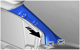
Insert the guide in the direction indicated by the arrow shown in the illustration.
|
|
Install in this Direction |
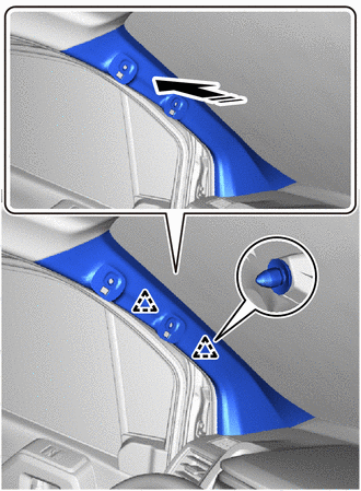
Push in the direction indicated by the arrow shown in the illustration to attach the clip to install the front pillar garnish LH.
62211
51.INSTALL FRONT PILLAR GARNISH RH
- HINT:
-
Use the same procedure described for the LH side.
74680
52.INSTALL PILLAR ASSIST GRIP ASSEMBLY LH
74680
53.INSTALL PILLAR ASSIST GRIP ASSEMBLY RH
- HINT:
-
Use the same procedure described for the LH side.
62312B
54.INSTALL FRONT DOOR OPENING TRIM WEATHERSTRIP LH
62311B
55.INSTALL FRONT DOOR OPENING TRIM WEATHERSTRIP RH
- HINT:
-
Use the same procedure described for the LH side.
62112
56.INSTALL COWL SIDE TRIM BOARD LH
62111C
57.INSTALL COWL SIDE TRIM BOARD RH
- HINT:
-
Use the same procedure described for the LH side.
67914B
58.INSTALL FRONT DOOR SCUFF PLATE LH
67912A
59.INSTALL FRONT DOOR OUTSIDE SCUFF PLATE LH
67913B
60.INSTALL FRONT DOOR SCUFF PLATE RH
- HINT:
-
Use the same procedure described for the LH side.
67911B
61.INSTALL FRONT DOOR OUTSIDE SCUFF PLATE RH
- HINT:
-
Use the same procedure described for the LH side.
62.CONNECT CABLE TO NEGATIVE BATTERY TERMINAL (w/ Airbag System)
63. INITIALIZATION AFTER RECONNECTING BATTERY TERMINAL (w/ Airbag System)
- HINT:
-
When disconnecting and reconnecting the battery, there is an automatic learning function that completes learning when the respective system is used.
64. PERFORM DIAGNOSTIC SYSTEM CHECK (w/ Airbag System)
65.CHECK SRS WARNING LIGHT (w/ Airbag System)
66.INSPECT SEAT BELT WARNING SYSTEM (w/ Seat Belt Warning System)