SEAT SEAT RAIL REMOVAL
CAUTION / NOTICE / HINT
- CAUTION:
- ·
Wear protective gloves. Sharp areas on the parts may injure your hands.
·There is risk of injury.
The necessary procedures (adjustment, calibration, initialization or registration) that must be performed after parts are removed, installed or replaced during the seat rail removal/installation are shown below.
| Replacement Part or Procedure | Necessary Procedures | Effect/Inoperative Function When Necessary Procedures not Performed | Link |
|---|---|---|---|
| Disconnect cable from negative (-) battery terminal | Memorize steering angle neutral point | Parking assist monitor system | ( 201902,999999,_56,_079315,_0385736,RM100000001GNRA,) 201902,999999,_56,_079315,_0385736,RM100000001GNRA,)
|
| Panoramic view monitor system | (201906,999999,_56,_079315,_0396274,RM100000001IGR3,)
|
- HINT:
- ·
When the cable is disconnected / reconnected to the battery terminal, systems temporarily stop operating. However, each system has a function that completes learning the first time the systems is used.
-Learning completes when vehicle is driven
Effect/Inoperative Function When Necessary Procedures not Performed Necessary Procedures Link Stop and start system Drive the vehicle until stop and start control is permitted (approximately 5 to 60 minutes). ( 201902,999999,_51,_078825,_0382334,RM100000001GBQ1,)
Lane control system Drive the vehicle straight ahead at 15 km/h (10 mph) or more for 1 second or more. ( 201902,999999,_58,_078886,_0382740,RM100000001G6XB,)
Pre-collision system
-Learning completes when vehicle is operated normally
Effect/Inoperative Function When Necessary Procedures not Performed Necessary Procedures Link Power slide door system Fully close the slide door by hand.
- HINT:
-
Initialization is not necessary if the above procedures are performed while the slide door is closed.
( 201902,999999,_59,_078503,_0381017,RM100000001FWXM,)
Air conditioning system After the ignition switch is turned to ON, the servo motor standard position is recognized. -
·Use the same procedure for RHD and LHD vehicles.
·The procedure listed below is for LHD vehicles.
·The procedure listed below is a representative example.
PROCEDURE

 1. PRECAUTION
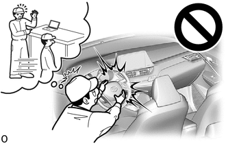
- CAUTION:
-
-
Be sure to read Precaution thoroughly before servicing.
- ·
- NOTICE:
- ·
After turning the ignition switch off, waiting time may be required before disconnecting the cable from the negative (-) battery terminal.
·If the pretensioner has been deployed, replace any damaged parts as necessary.
2.DISCONNECT CABLE FROM NEGATIVE BATTERY TERMINAL
for Power Captain Seat:
Operate the rear power seat switch and move the ottoman to the uppermost position and seatback to the frontmost position.
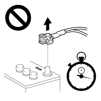
Disconnect the cable from the negative (-) battery terminal.
- CAUTION:
-
- ·
Wait at least 90 seconds after disconnecting the cable from the negative (-) battery terminal to disable the SRS system.
·If the airbag deploys for any reason, it may cause a serious accident.
67912A
3.REMOVE FRONT DOOR OUTSIDE SCUFF PLATE LH
67914B
4.REMOVE FRONT DOOR SCUFF PLATE LH
67911B
5.REMOVE FRONT DOOR OUTSIDE SCUFF PLATE RH
- HINT:
-
Use the same procedure described for the LH side.
67913B
6.REMOVE FRONT DOOR SCUFF PLATE RH
- HINT:
-
Use the same procedure described for the LH side.
62312B
7.REMOVE FRONT DOOR OPENING TRIM WEATHERSTRIP LH
- HINT:
-
Pull back the front door opening trim weatherstrip LH so that the lower center pillar garnish LH can be removed.
62311B
8.REMOVE FRONT DOOR OPENING TRIM WEATHERSTRIP RH
- HINT:
-
Use the same procedure described for the LH side.
9.REMOVE FRONT SEAT ASSEMBLY
for Separate Seat Type:
for Sliding Bench Seat Type:
10.REMOVE REAR SEAT ASSEMBLY
for 60/40 Split Seat Type 40 Side:
for 60/40 Split Seat Type 60 Side:
for Manual Captain Seat:
for Power Captain Seat:
73233D
11.REMOVE OUTER LAP BELT ANCHOR COVER
73220
12.REMOVE FRONT SEAT OUTER BELT ASSEMBLY LH (FLOOR ANCHOR)
73210
13.REMOVE FRONT SEAT OUTER BELT ASSEMBLY RH (FLOOR ANCHOR)
- HINT:
-
Use the same procedure described for the LH side.
67918D
14.REMOVE REAR DOOR SCUFF PLATE LH
- HINT:
-
Use the same procedure described for the RH side.
67917C
15.REMOVE REAR DOOR SCUFF PLATE RH
67872A
16.REMOVE NO. 1 SLIDE DOOR WEATHERSTRIP LH
- HINT:
- ·
Use the same procedure described for the RH side.
·Pull back the No. 1 slide door weatherstrip LH so that the lower center pillar garnish LH can be removed.
67871E
17.REMOVE NO. 1 SLIDE DOOR WEATHERSTRIP RH
- HINT:
-
Pull back the No. 1 slide door weatherstrip RH so that the lower center pillar garnish RH can be removed.
74617A
18.REMOVE ASSIST GRIP PLUG
74680
19.REMOVE PILLAR ASSIST GRIP ASSEMBLY B
62414A
20.REMOVE LOWER CENTER PILLAR GARNISH LH
- HINT:
-
Use the same procedure described for the RH side.
62413A
21.REMOVE LOWER CENTER PILLAR GARNISH RH
67935
22.REMOVE BACK DOOR SCUFF PLATE
73233D
23.REMOVE OUTER LAP BELT ANCHOR COVER (w/ Seat Belt)
73570A
24.REMOVE NO. 3 SEAT OUTER BELT ASSEMBLY LH (FLOOR ANCHOR) (w/ Seat Belt)
73560A
25.REMOVE NO. 3 SEAT OUTER BELT ASSEMBLY RH (FLOOR ANCHOR) (w/ Seat Belt)
- HINT:
-
Use the same procedure described for the LH side.
67872A
26.REMOVE NO. 1 SLIDE DOOR WEATHERSTRIP LH
- HINT:
- ·
Use the same procedure described for the RH side.
·Pull back the No. 1 slide door weatherstrip LH so that the quarter trim panel assembly LH can be removed.
67871E
27.REMOVE NO. 1 SLIDE DOOR WEATHERSTRIP RH
- HINT:
-
Pull back the No. 1 slide door weatherstrip RH so that the rear quarter trim board assembly RH can be removed.
62520B
28.REMOVE QUARTER TRIM PANEL ASSEMBLY LH
62510M
29.REMOVE QUARTER TRIM PANEL ASSEMBLY RH
30.REMOVE REAR SEAT TRACK SLIDE STOPPER
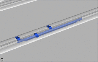
Remove the each rear seat track slide stopper.
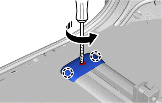
31.REMOVE NO. 3 FLOOR NO. 1 CARPET MOULDING


|
Rotate in this Direction |

|
Protective Tape |
Using a screwdriver, rotate the screw portion of the clip 90° counterclockwise to unlock it.
- HINT:
-
Tape the screwdriver tip before use.
Detach the claw and remove each No. 3 floor No. 1 carpet moulding.
32.REMOVE NO. 3 FLOOR NO. 2 CARPET MOULDING
|
|
Rotate in this Direction |
|
|
Protective Tape |
Using a screwdriver, rotate the screw portion of the clip 90° counterclockwise to unlock it.
- HINT:
-
Tape the screwdriver tip before use.
Detach the claw and remove each No. 3 floor No. 2 carpet moulding.
33.REMOVE NO. 3 FLOOR NO. 3 CARPET MOULDING (w/ Power Supply Unit)
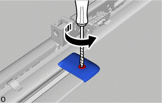
|
|
Rotate in this Direction |
|
|
Protective Tape |
Using a screwdriver, rotate the screw portion of the clip 90° counterclockwise to unlock it and remove the No. 3 floor No. 3 carpet moulding.
- HINT:
-
Tape the screwdriver tip before use.
34.REMOVE NO. 3 FLOOR NO. 4 CARPET MOULDING (w/ Power Supply Unit)
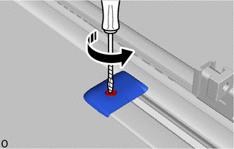
|
|
Rotate in this Direction |
|
|
Protective Tape |
Using a screwdriver, rotate the screw portion of the clip 90° counterclockwise to unlock it and remove the No. 3 floor No. 4 carpet moulding.
- HINT:
-
Tape the screwdriver tip before use.
35.REMOVE SEAT TRACK RAIL PROTECTOR
Using a screwdriver, turn it in the direction indicated by the arrow shown in the illustration to detach the claw and remove all seat track rail protectors.
- HINT:
- ·
Tape the screwdriver tip before use.
·The procedure is a representative example.
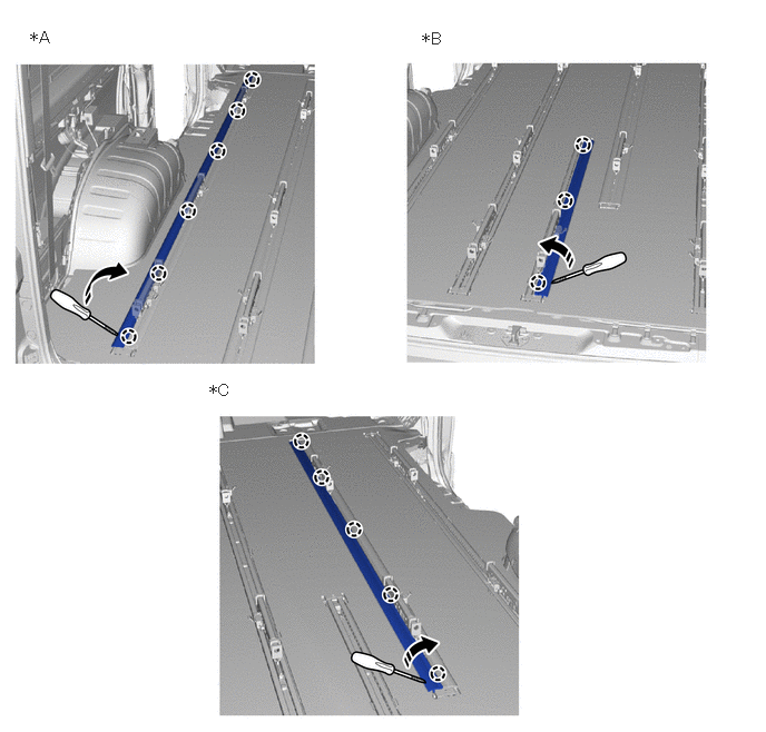
| *A | for Type A | *B | for Type B |
| *C | for Type C | - | - |
|
|
Turn in this Direction |
|
Protective Tape |
36.REMOVE REAR FLOOR CARPET ASSEMBLY
Remove the rear floor carpet assembly.
37.REMOVE REAR FLOOR SILENCER
Remove each rear floor silencer.
38.REMOVE WHEEL ASSEMBLY (Rear LH)
39.REMOVE WHEEL ASSEMBLY (Rear RH)
- HINT:
-
Use the same procedure described for the LH side.
65632D
40.REMOVE REAR FRONT WHEEL HOUSE PLATE LH
65631D
41.REMOVE REAR FRONT WHEEL HOUSE PLATE RH
- HINT:
-
Use the same procedure described for the LH side.
76908
42.REMOVE QUARTER PANEL MUDGUARD SUB-ASSEMBLY LH
76907
43.REMOVE QUARTER PANEL MUDGUARD SUB-ASSEMBLY RH
- HINT:
-
Use the same procedure described for the LH side.
65638A
44.REMOVE REAR WHEEL HOUSE LINER LH
- HINT:
-
Use the same procedure described for the RH side.
65637B
45.REMOVE REAR WHEEL HOUSE LINER RH
77100
46.REMOVE FUEL TANK ASSEMBLY
47.REMOVE EXHAUST PIPE ASSEMBLY
58399D
48.REMOVE NO. 2 FLOOR UNDER COVER
49.REMOVE SPARE TIRE
58398R
50.REMOVE LOWER BODY BACK COVER LH
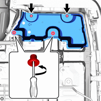
Remove the 2 clips.
Using a screwdriver, loosen the 2 clips and remove the lower body back cover LH.
58155
51.REMOVE NO. 3 FRONT FLOOR HEAT INSULATOR
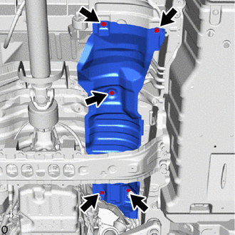
Remove the 5 bolts and No. 3 front floor heat insulator.
58045
52.REMOVE REAR FLOOR HEAT INSULATOR SUB-ASSEMBLY
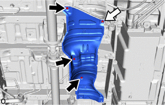

|
Bolt |

|
Nut |
Remove the nut, 3 bolts and rear floor heat insulator sub-assembly.
58328B
53.REMOVE LOWER MAIN MUFFLER HEAT INSULATOR
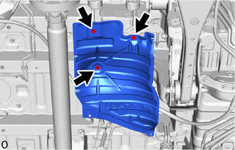
Remove the 3 bolts and lower main muffler heat insulator.
58321B
54.REMOVE REAR NO. 1 FLOOR HEAT INSULATOR
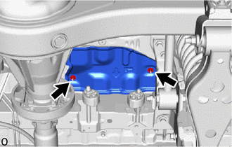
Remove the 2 nuts and rear No. 1 floor heat insulator.
58322B
55.REMOVE REAR NO. 2 FLOOR HEAT INSULATOR
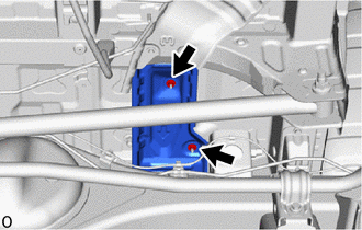
Remove the 2 nuts and rear No. 2 floor heat insulator.
58323C
56.REMOVE REAR NO. 3 FLOOR HEAT INSULATOR
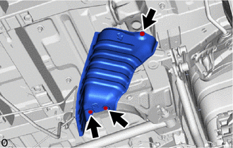
Remove the 3 bolts and rear No. 3 floor heat insulator.
72170A
57.REMOVE REAR OUTER SEAT TRACK ASSEMBLY LH
for Folding Seat Type:
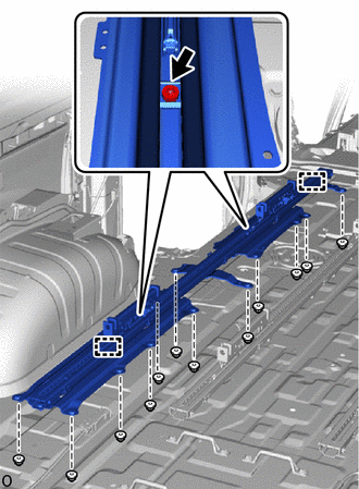
Using a T50 "TORX" socket wrench, loosen the 2 "TORX" bolts.
Remove the 12 nuts from the bottom of the vehicle.
Detach the guide and remove the rear outer seat track assembly LH.
except Folding Seat Type:
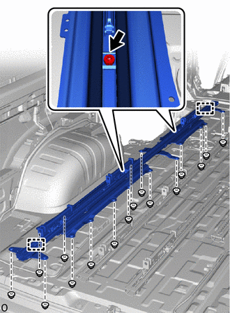
Using a T50 "TORX" socket wrench, loosen the 2 "TORX" bolts.
Remove the 16 nuts from the bottom of the vehicle.
Detach the guide and remove the rear outer seat track assembly LH.
82807
58.REMOVE WIRING HARNESS PROTECTOR SET (w/ Power Supply Unit)
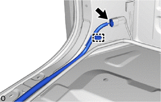
Disconnect the connector.
Detach the clamp.
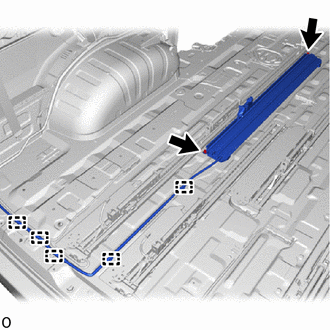
Detach the clamp and remove the 2 nuts and wiring harness protector set.
72190E
59.REMOVE REAR INNER SEAT TRACK ASSEMBLY LH
Fold back the front floor carpet assembly.
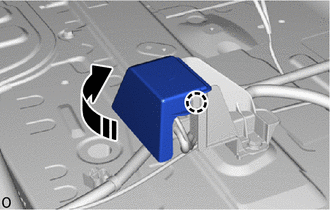
|
|
Open in this Direction |
Detach the claw and open the cover.
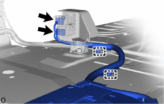
Disconnect the 2 connectors.
Detach the clamp.
for Folding Seat Type:
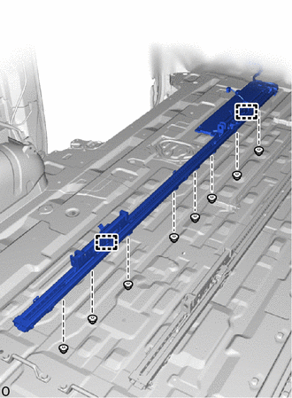
Remove the 8 nuts from the bottom of the vehicle.
Detach the guide and remove the rear inner seat track assembly LH.
except Folding Seat Type:
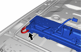
w/ Power Supply Unit:
Disconnect the connector.
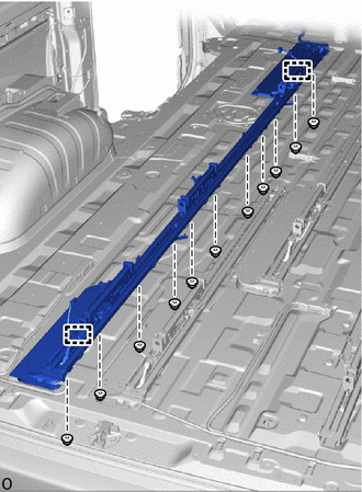
Remove the 11 nuts from the bottom of the vehicle.
Detach the guide and remove the rear inner seat track assembly LH.
w/o Rear No. 3 Seat:
Disconnect the connector.
Detach the clamp.
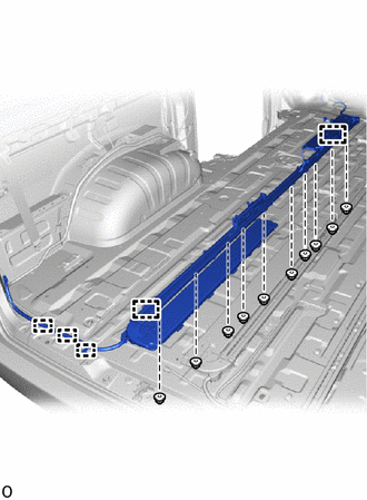
Remove the 10 nuts from the bottom of the vehicle.
Detach the guide and remove the rear inner seat track assembly LH.
72180F
60.REMOVE REAR INNER SEAT TRACK ASSEMBLY RH
Fold back the front floor carpet assembly.
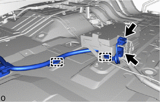
Disconnect the 2 connectors.
Detach the clamp.
for Folding Seat Type:
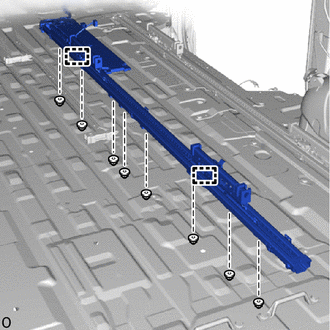
Remove the 8 nuts from the bottom of the vehicle.
Detach the guide and remove the rear inner seat track assembly RH.
except Folding Seat Type:
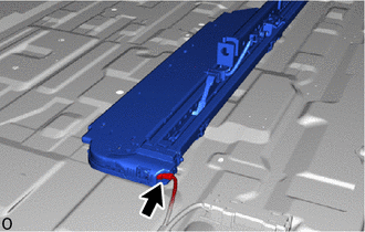
w/ Power Supply Unit:
Disconnect the connector.
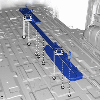
Remove the 8 nuts from the bottom of the vehicle, and remove the rear inner seat track assembly RH.
Detach the guide and remove the rear inner seat track assembly RH.
w/o Rear No. 3 Seat:
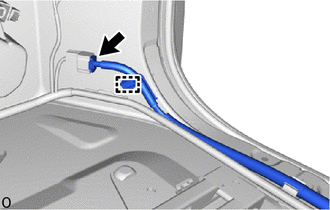
Disconnect the connector.
Detach the clamp.
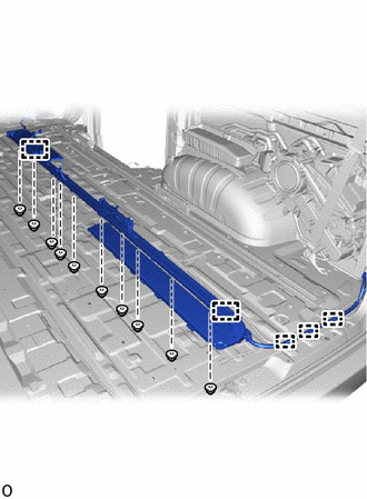
Detach the clamp and remove the 10 nuts from the bottom of the vehicle.
Detach the guide and remove the rear inner seat track assembly RH.
72180G
61.REMOVE REAR INNER REAR SEAT TRACK ASSEMBLY RH
w/ Power Supply Unit:
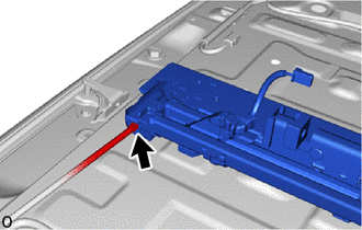
Disconnect the connector.
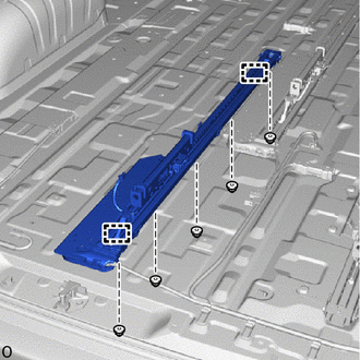
Remove the 5 nuts from the bottom of the vehicle.
Detach the guide and remove the rear inner rear seat track assembly RH.
72160H
62.REMOVE REAR OUTER SEAT TRACK ASSEMBLY RH
for Folding Seat Type:
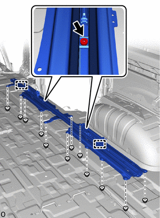
Using a T50 "TORX" socket wrench, loosen the 2 "TORX" bolts.
Remove the 12 nuts from the bottom of the vehicle.
Detach the guide and remove the rear outer seat track assembly RH.
except Folding Seat Type:
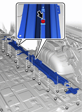
Using a T50 "TORX" socket wrench, loosen the 2 "TORX" bolts.
Remove the 16 nuts from the bottom of the vehicle.
Detach the guide and remove the rear outer seat track assembly RH.