LIGHTING (INT) LIGHTING SYSTEM Instrument Panel Illumination does not Turn On
DESCRIPTION
The power distribution box assembly controls the instrument panel illuminations.
WIRING DIAGRAM
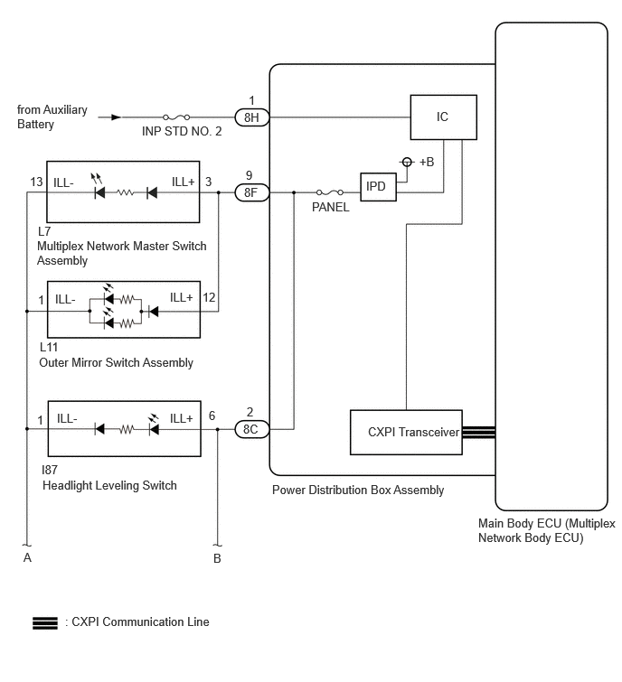
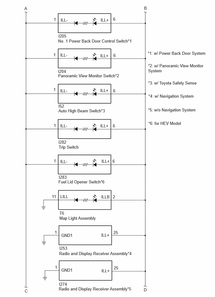
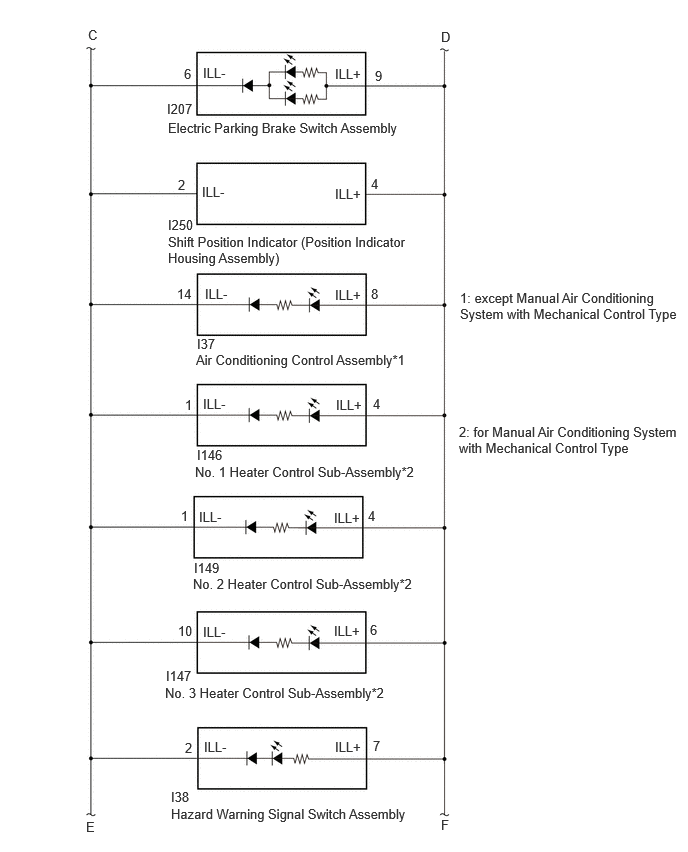
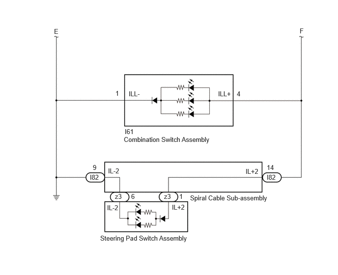
CAUTION / NOTICE / HINT
- NOTICE:
- ·
Inspect the fuses for circuits related to this system before performing the following procedure.
·Before replacing the main body ECU (multiplex network body ECU), refer to Service Bulletin.*1
*1: w/ Smart Entry and Start System
PROCEDURE
Turn the light control switch to the TAIL position.
Read the Data List according to the display on the GTS.
- Body Electrical > Power Distribution Box > Data List
-
Tester Display Measurement Item Range Normal Condition Diagnostic Note Panel Light Fuse Shut Off Status Panel Light Fuse condition OFF or ON OFF: Fuse not shut off
ON: Fuse shut off-
- Body Electrical > Power Distribution Box > Data List
-
Tester Display Panel Light Fuse Shut Off Status - 50003 475 1298
- OK:
The Data List value displays "OFF".
- Result:
Proceed to OK NG
OK
NG
Read the Data List according to the display on the GTS.
- Body Electrical > Power Distribution Box > Data List
-
Tester Display Measurement Item Range Normal Condition Diagnostic Note Panel Light Input Signal Panel light input condition OFF or ON OFF: Light control switch not in tail position
ON: Light control switch in tail position-
- Body Electrical > Power Distribution Box > Data List
-
Tester Display Panel Light Input Signal - 50003 475 1295
- OK:
The GTS display changes.
- Result:
Proceed to OK NG
OK
NG
Disconnect the L11 outer mirror switch assembly connector.
Turn the light control switch to the TAIL position.
Read the Data List according to the display on the GTS.
- Body Electrical > Power Distribution Box > Data List
-
Tester Display Measurement Item Range Normal Condition Diagnostic Note Panel Light Fuse Shut Off Status Panel Light Fuse condition OFF or ON OFF: Fuse not shut off
ON: Fuse shut off-
- Body Electrical > Power Distribution Box > Data List
-
Tester Display Panel Light Fuse Shut Off Status - 50003 475 1298
- OK:
The Data List value displays "OFF".
- Result:
Proceed to OK NG
OK
NG
Disconnect the L7 multiplex network master switch assembly connector.
Turn the light control switch to the TAIL position.
Read the Data List according to the display on the GTS.
- Body Electrical > Power Distribution Box > Data List
-
Tester Display Measurement Item Range Normal Condition Diagnostic Note Panel Light Fuse Shut Off Status Panel Light Fuse condition OFF or ON OFF: Fuse not shut off
ON: Fuse shut off-
- Body Electrical > Power Distribution Box > Data List
-
Tester Display Panel Light Fuse Shut Off Status - 50003 475 1298
- OK:
The Data List value displays "OFF".
- Result:
Result Proceed to OK A NG B
A
B
- NOTICE:
-
For vehicle without automatic high beam system, proceed to next step.
Disconnect the I52 auto high beam switch connector.
Turn the light control switch to the TAIL position.
Read the Data List according to the display on the GTS.
- Body Electrical > Power Distribution Box > Data List
-
Tester Display Measurement Item Range Normal Condition Diagnostic Note Panel Light Fuse Shut Off Status Panel Light Fuse condition OFF or ON OFF: Fuse not shut off
ON: Fuse shut off-
- Body Electrical > Power Distribution Box > Data List
-
Tester Display Panel Light Fuse Shut Off Status - 50003 475 1298
- OK:
The Data List value displays "OFF".
- Result:
Proceed to OK NG
OK
NG
Disconnect the I250 shift position indicator (position indicator housing assembly) connector.
Turn the light control switch to the TAIL position.
Read the Data List according to the display on the GTS.
- Body Electrical > Power Distribution Box > Data List
-
Tester Display Measurement Item Range Normal Condition Diagnostic Note Panel Light Fuse Shut Off Status Panel Light Fuse condition OFF or ON OFF: Fuse not shut off
ON: Fuse shut off-
- Body Electrical > Power Distribution Box > Data List
-
Tester Display Panel Light Fuse Shut Off Status - 50003 475 1298
- OK:
The Data List value displays "OFF".
- Result:
Proceed to OK NG
OK
Click hereDrivetrain>K121 (CVT)>SHIFT LEVER>REMOVAL202201,999999,_52,_139996,_0585165,RM1000000029IX9,
NG
Disconnect the I61 combination switch assembly connector.
Turn the light control switch to the TAIL position.
Read the Data List according to the display on the GTS.
- Body Electrical > Power Distribution Box > Data List
-
Tester Display Measurement Item Range Normal Condition Diagnostic Note Panel Light Fuse Shut Off Status Panel Light Fuse condition OFF or ON OFF: Fuse not shut off
ON: Fuse shut off-
- Body Electrical > Power Distribution Box > Data List
-
Tester Display Panel Light Fuse Shut Off Status - 50003 475 1298
- OK:
The Data List value displays "OFF".
- Result:
Proceed to OK NG
OK
NG
Disconnect the I207 electric parking brake switch assembly connector.
Turn the light control switch to the TAIL position.
Read the Data List according to the display on the GTS.
- Body Electrical > Power Distribution Box > Data List
-
Tester Display Measurement Item Range Normal Condition Diagnostic Note Panel Light Fuse Shut Off Status Panel Light Fuse condition OFF or ON OFF: Fuse not shut off
ON: Fuse shut off-
- Body Electrical > Power Distribution Box > Data List
-
Tester Display Panel Light Fuse Shut Off Status - 50003 475 1298
- OK:
The Data List value displays "OFF".
- Result:
Proceed to OK NG
OK
NG
Disconnect the I87 Headlight Leveling Switch connector.
Turn the light control switch to the TAIL position.
Read the Data List according to the display on the GTS.
- Body Electrical > Power Distribution Box > Data List
-
Tester Display Measurement Item Range Normal Condition Diagnostic Note Panel Light Fuse Shut Off Status Panel Light Fuse condition OFF or ON OFF: Fuse not shut off
ON: Fuse shut off-
- Body Electrical > Power Distribution Box > Data List
-
Tester Display Panel Light Fuse Shut Off Status - 50003 475 1298
- OK:
The Data List value displays "OFF".
- Result:
Proceed to OK NG
OK
NG
Check vehicle type.
- Result:
Result Proceed to except Manual Air Conditioning System with Mechanical Control Type A for Manual Air Conditioning System with Mechanical Control Type B
A
B
Disconnect the I37 air conditioning control assembly connector.
Turn the light control switch to the TAIL position.
Read the Data List according to the display on the GTS.
- Body Electrical > Power Distribution Box > Data List
-
Tester Display Measurement Item Range Normal Condition Diagnostic Note Panel Light Fuse Shut Off Status Panel Light Fuse condition OFF or ON OFF: Fuse not shut off
ON: Fuse shut off-
- Body Electrical > Power Distribution Box > Data List
-
Tester Display Panel Light Fuse Shut Off Status - 50003 475 1298
- OK:
The Data List value displays "OFF".
- Result:
Proceed to OK NG
OK
NG
Disconnect the I146 No. 1 heater control sub-assembly connector.
Turn the light control switch to the TAIL position.
Read the Data List according to the display on the GTS.
- Body Electrical > Power Distribution Box > Data List
-
Tester Display Measurement Item Range Normal Condition Diagnostic Note Panel Light Fuse Shut Off Status Panel Light Fuse condition OFF or ON OFF: Fuse not shut off
ON: Fuse shut off-
- Body Electrical > Power Distribution Box > Data List
-
Tester Display Panel Light Fuse Shut Off Status - 50003 475 1298
- OK:
The Data List value displays "OFF".
- Result:
Proceed to OK NG
OK
NG
Disconnect the I149 No. 2 heater control sub-assembly connector.
Turn the light control switch to the TAIL position.
Read the Data List according to the display on the GTS.
- Body Electrical > Power Distribution Box > Data List
-
Tester Display Measurement Item Range Normal Condition Diagnostic Note Panel Light Fuse Shut Off Status Panel Light Fuse condition OFF or ON OFF: Fuse not shut off
ON: Fuse shut off-
- Body Electrical > Power Distribution Box > Data List
-
Tester Display Panel Light Fuse Shut Off Status - 50003 475 1298
- OK:
The Data List value displays "OFF".
- Result:
Proceed to OK NG
OK
NG
Disconnect the I147 No. 3 heater control sub-assembly connector.
Turn the light control switch to the TAIL position.
Read the Data List according to the display on the GTS.
- Body Electrical > Power Distribution Box > Data List
-
Tester Display Measurement Item Range Normal Condition Diagnostic Note Panel Light Fuse Shut Off Status Panel Light Fuse condition OFF or ON OFF: Fuse not shut off
ON: Fuse shut off-
- Body Electrical > Power Distribution Box > Data List
-
Tester Display Panel Light Fuse Shut Off Status - 50003 475 1298
- OK:
The Data List value displays "OFF".
- Result:
Proceed to OK NG
OK
NG
Disconnect the I82 spiral cable sub-assembly connector.
Turn the light control switch to the TAIL position.
Read the Data List according to the display on the GTS.
- Body Electrical > Power Distribution Box > Data List
-
Tester Display Measurement Item Range Normal Condition Diagnostic Note Panel Light Fuse Shut Off Status Panel Light Fuse condition OFF or ON OFF: Fuse not shut off
ON: Fuse shut off-
- Body Electrical > Power Distribution Box > Data List
-
Tester Display Panel Light Fuse Shut Off Status - 50003 475 1298
- OK:
The Data List value displays "OFF".
- Result:
Proceed to OK NG
OK
NG
Disconnect the z3 steering pad switch assembly connector.
Turn the light control switch to the TAIL position.
Read the Data List according to the display on the GTS.
- Body Electrical > Power Distribution Box > Data List
-
Tester Display Measurement Item Range Normal Condition Diagnostic Note Panel Light Fuse Shut Off Status Panel Light Fuse condition OFF or ON OFF: Fuse not shut off
ON: Fuse shut off-
- Body Electrical > Power Distribution Box > Data List
-
Tester Display Panel Light Fuse Shut Off Status - 50003 475 1298
- OK:
The Data List value displays "OFF".
- Result:
Proceed to OK NG
OK
NG
Disconnect the I38 hazard warning signal switch assembly connector.
Turn the light control switch to the TAIL position.
Read the Data List according to the display on the GTS.
- Body Electrical > Power Distribution Box > Data List
-
Tester Display Measurement Item Range Normal Condition Diagnostic Note Panel Light Fuse Shut Off Status Panel Light Fuse condition OFF or ON OFF: Fuse not shut off
ON: Fuse shut off-
- Body Electrical > Power Distribution Box > Data List
-
Tester Display Panel Light Fuse Shut Off Status - 50003 475 1298
- OK:
The Data List value displays "OFF".
- Result:
Proceed to OK NG
OK
NG
- NOTICE:
-
For vehicle without power back door system, proceed to next step.
Disconnect the I205 No.1 power back door control switch connector.
Turn the light control switch to the TAIL position.
Read the Data List according to the display on the GTS.
- Body Electrical > Power Distribution Box > Data List
-
Tester Display Measurement Item Range Normal Condition Diagnostic Note Panel Light Fuse Shut Off Status Panel Light Fuse condition OFF or ON OFF: Fuse not shut off
ON: Fuse shut off-
- Body Electrical > Power Distribution Box > Data List
-
Tester Display Panel Light Fuse Shut Off Status - 50003 475 1298
- OK:
The Data List value displays "OFF".
- Result:
Proceed to OK NG
OK
NG
Check vehicle type.
- Result:
Result Proceed to w/ Navigation System A w/o Navigation System B
A
B
Disconnect the I253 radio and display receiver assembly connector.
Turn the light control switch to the TAIL position.
Read the Data List according to the display on the GTS.
- Body Electrical > Power Distribution Box > Data List
-
Tester Display Measurement Item Range Normal Condition Diagnostic Note Panel Light Fuse Shut Off Status Panel Light Fuse condition OFF or ON OFF: Fuse not shut off
ON: Fuse shut off-
- Body Electrical > Power Distribution Box > Data List
-
Tester Display Panel Light Fuse Shut Off Status - 50003 475 1298
- OK:
The Data List value displays "OFF".
- Result:
Proceed to OK NG
OK
NG
Disconnect the I274 radio and display receiver assembly connector.
Turn the light control switch to the TAIL position.
Read the Data List according to the display on the GTS.
- Body Electrical > Power Distribution Box > Data List
-
Tester Display Measurement Item Range Normal Condition Diagnostic Note Panel Light Fuse Shut Off Status Panel Light Fuse condition OFF or ON OFF: Fuse not shut off
ON: Fuse shut off-
- Body Electrical > Power Distribution Box > Data List
-
Tester Display Panel Light Fuse Shut Off Status - 50003 475 1298
- OK:
The Data List value displays "OFF".
- Result:
Proceed to OK NG
OK
NG
Disconnect the T6 map light assembly connector.
Turn the light control switch to the TAIL position.
Read the Data List according to the display on the GTS.
- Body Electrical > Power Distribution Box > Data List
-
Tester Display Measurement Item Range Normal Condition Diagnostic Note Panel Light Fuse Shut Off Status Panel Light Fuse condition OFF or ON OFF: Fuse not shut off
ON: Fuse shut off-
- Body Electrical > Power Distribution Box > Data List
-
Tester Display Panel Light Fuse Shut Off Status - 50003 475 1298
- OK:
The Data List value displays "OFF".
- Result:
Proceed to OK NG
OK
NG
- NOTICE:
-
For vehicle without panoramic view monitor system, proceed to next step.
Disconnect the I204 panoramic view monitor switch connector.
Turn the light control switch to the TAIL position.
Read the Data List according to the display on the GTS.
- Body Electrical > Power Distribution Box > Data List
-
Tester Display Measurement Item Range Normal Condition Diagnostic Note Panel Light Fuse Shut Off Status Panel Light Fuse condition OFF or ON OFF: Fuse not shut off
ON: Fuse shut off-
- Body Electrical > Power Distribution Box > Data List
-
Tester Display Panel Light Fuse Shut Off Status - 50003 475 1298
- OK:
The Data List value displays "OFF".
- Result:
Proceed to OK NG
OK
NG
Disconnect the I282 trip switch connector.
Turn the light control switch to the TAIL position.
Read the Data List according to the display on the GTS.
- Body Electrical > Power Distribution Box > Data List
-
Tester Display Measurement Item Range Normal Condition Diagnostic Note Panel Light Fuse Shut Off Status Panel Light Fuse condition OFF or ON OFF: Fuse not shut off
ON: Fuse shut off-
- Body Electrical > Power Distribution Box > Data List
-
Tester Display Panel Light Fuse Shut Off Status - 50003 475 1298
- OK:
The Data List value displays "OFF".
- Result:
Proceed to OK NG
OK
NG
- NOTICE:
-
For vehicle without fuel lid opener switch, proceed to next step.
Disconnect the I283 fuel lid opener switch connector.
Turn the light control switch to the TAIL position.
Read the Data List according to the display on the GTS.
- Body Electrical > Power Distribution Box > Data List
-
Tester Display Measurement Item Range Normal Condition Diagnostic Note Panel Light Fuse Shut Off Status Panel Light Fuse condition OFF or ON OFF: Fuse not shut off
ON: Fuse shut off-
- Body Electrical > Power Distribution Box > Data List
-
Tester Display Panel Light Fuse Shut Off Status - 50003 475 1298
- OK:
The Data List value displays "OFF".
- Result:
Proceed to OK NG
OK
NG
Disconnect the L7 multiplex network master switch assembly connector.
Disconnect the L11 outer mirror switch assembly connector.
Disconnect the I52 auto high beam switch connector. (w/ Toyota Safety Sense)
Disconnect the I250 shift position indicator (position indicator housing assembly) connector.
Disconnect the I61 combination switch assembly connector.
Disconnect the I207 electric parking brake switch assembly connector.
Disconnect the I87 headlight leveling switch connector.
Disconnect the I204 panoramic view monitor switch connector.
Disconnect the T6 map light assembly connector.
Disconnect the I37 air conditioning control assembly connector. (Except for Manual Air Conditioning System with PTC Heater)
Disconnect the I146 No. 1 heater control sub-assembly connector. (for Manual Air Conditioning System with PTC Heater)
Disconnect the I149 No. 2 heater control sub-assembly connector. (for Manual Air Conditioning System with PTC Heater)
Disconnect the I147 No. 3 heater control sub-assembly connector. (for Manual Air Conditioning System with PTC Heater)
Disconnect the z3 steering pad switch assembly connector.
Disconnect the I82 spiral cable sub-assembly connector.
Disconnect the I38 hazard warning signal switch assembly connector.
Disconnect the I205 power back door control switch connector. (w/ Power Back Door System)
Disconnect the I253 radio and display receiver assembly connector. (w/ Navigation System)
Disconnect the I282 trip switch connector.
Disconnect the I283 fuel lid opener switch connector. (for HEV Model)
Disconnect the I274 radio and display receiver assembly connector. (w/o Navigation System)
Disconnect the cable from the negative (-) auxiliary battery terminal.
Disconnect the 8C and 8F power distribution box assembly connectors.
Measure the resistance according to the value(s) in the table below.
- Standard Resistance:
Tester Connection Condition Specified Condition L7-3 (ILL+) - 8F-9 Always Below 1 Ω L11-12 (ILL+) - 8F-9 Always Below 1 Ω I87-6 (ILL+) - 8C-2 Always Below 1 Ω I205-6 (ILL+) - 8C-2*1 Always Below 1 Ω I204-6 (ILL+) - 8C-2*2 Always Below 1 Ω I52-6 (ILL+) - 8C-2*3 Always Below 1 Ω I253-25 (ILL+) - 8C-2*4 Always Below 1 Ω I283-6 (ILL+) - 8C-2*8 Always Below 1 Ω T6-2 (ILLB) - 8C-2 Always Below 1 Ω I207-9 (ILL+) - 8C-2 Always Below 1 Ω I250-4 (ILL+) - 8C-2 Always Below 1 Ω I37-8 (ILL+) - 8C-2*6 Always Below 1 Ω I146-4 (ILL+) - 8C-2*7 Always Below 1 Ω I149-4 (ILL+) - 8C-2*7 Always Below 1 Ω I147-6 (ILL+) - 8C-2*7 Always Below 1 Ω I38-7 (ILL+) - 8C-2 Always Below 1 Ω I61-4 (ILL+) - 8C-2 Always Below 1 Ω I82-14 (IL+2) - 8C-2 Always Below 1 Ω I282-6 (ILL+) - 8C-2 Always Below 1 Ω L7-3 (ILL+) or 8F-9 - Body ground Always 10 kΩ or higher L11-12 (ILL+) or 8F-9 - Body ground Always 10 kΩ or higher I87-6 (ILL+) or 8C-2 - Body ground Always 10 kΩ or higher I205-6 (ILL+) or 8C-2 - Body ground*1 Always 10 kΩ or higher I204-6 (ILL+) or 8C-2 - Body ground*2 Always 10 kΩ or higher I52-6 (ILL+) or 8C-2 - Body ground*3 Always 10 kΩ or higher I253-25 (ILL+) or 8C-2 - Body ground*4 Always 10 kΩ or higher I283-6 (ILL+) or 8C-2 - Body ground*8 Always 10 kΩ or higher T6-2 (ILLB) or 8C-2 - Body ground Always 10 kΩ or higher I207-9 (ILL+) or 8C-2 - Body ground Always 10 kΩ or higher I250-4 (ILL+) or 8C-2 - Body ground Always 10 kΩ or higher I37-8 (ILL+) or 8C-2 - Body ground*6 Always 10 kΩ or higher I146-4 (ILL+) or 8C-2 - Body ground*7 Always 10 kΩ or higher I149-4 (ILL+) or 8C-2 - Body ground*7 Always 10 kΩ or higher I147-6 (ILL+) or 8C-2 - Body ground*7 Always 10 kΩ or higher I38-7 (ILL+) or 8C-2 - Body ground Always 10 kΩ or higher I61-4 (ILL+) or 8C-2 - Body ground Always 10 kΩ or higher I82-14 (IL+2) or 8C-2 - Body ground Always 10 kΩ or higher I282-6 (ILL+) or 8C-2 - Body ground Always Below 1 Ω z3-1 (IL+2) or 8C-2 - Body ground Always 10 kΩ or higher 8C-2 - Body ground Always 10 kΩ or higher 8F-9 - Body ground Always 10 kΩ or higher
*1: w/ Power Back Door System
*2: w/ Panoramic View Monitor System
*3: w/ Toyota Safety Sense
*4: w/ Navigation System
*5: w/o Navigation System
*6: except Manual Air Conditioning System with Mechanical Control Type
*7: for Manual Air Conditioning System with Mechanical Control Type
*8: for HEV Model
- Result:
Proceed to OK NG
OK
NG