RM38N0EC _58 Vehicle Interior _111833 LIGHTING (INT) _0499871 LIGHTING SYSTEM J

LIGHTING (INT)  LIGHTING SYSTEM  Instrument Panel Illumination does not Turn On  


DESCRIPTION

The power distribution box assembly controls the instrument panel illuminations.

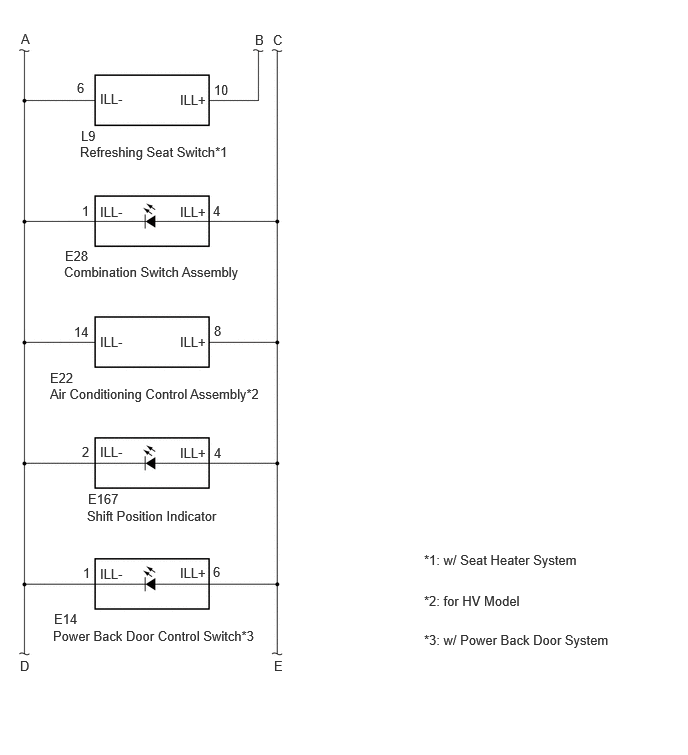
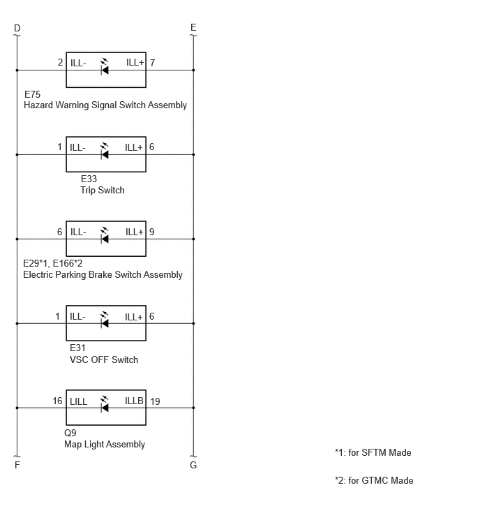
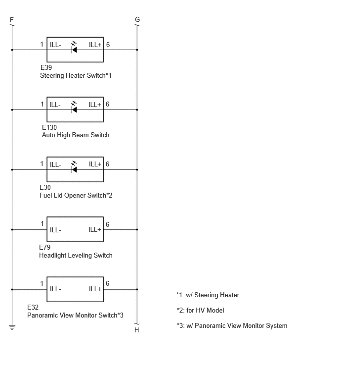
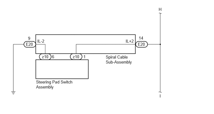
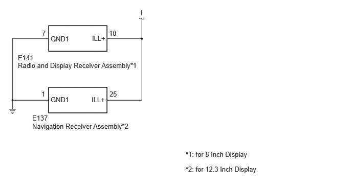
WIRING DIAGRAM
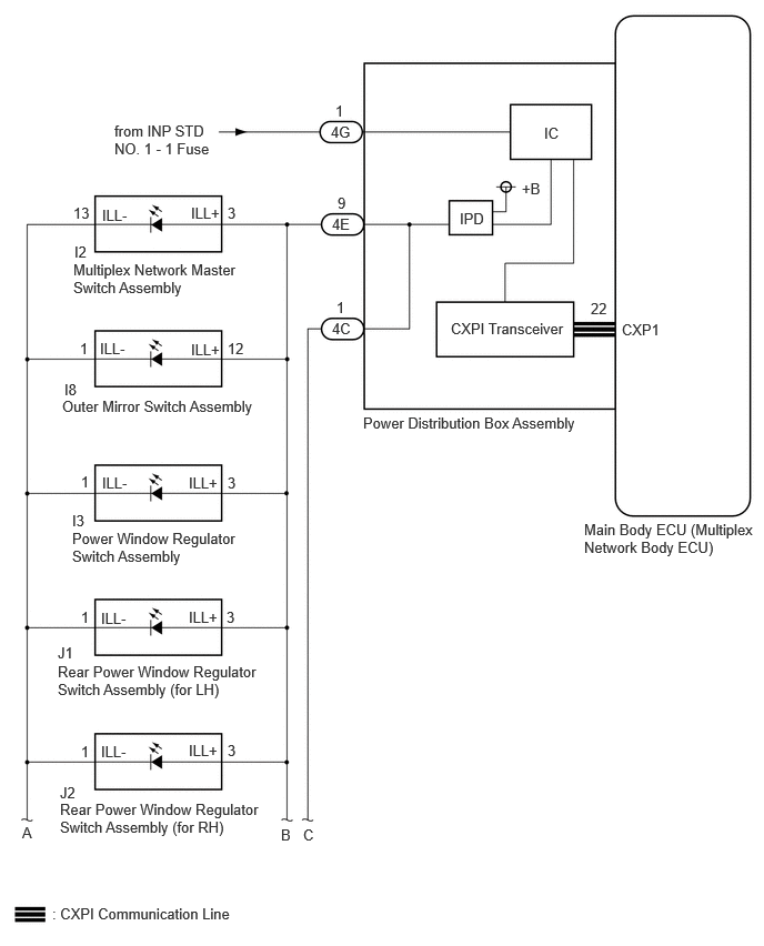
E444963E05
0.49,8.49 2.458,8.708 1.969,0.219 10 false : CXPI Communication Line 5.479,4.885 7.146,5.281 1.667,0.396 10 false Main Body ECU (Multiplex Network Body ECU) 3.406,3.885 5.521,4.281 2.115,0.396 10 false Power Distribution Box Assembly 4.229,3 5.76,3.198 1.531,0.198 10 false CXPI Transceiver 4.313,1.969 4.771,2.167 0.458,0.198 10 false IPD 4.896,1.688 5.354,1.885 0.458,0.198 10 false +B 5.104,1.167 5.563,1.365 0.458,0.198 10 false IC 3.104,1.156 3.417,1.354 0.313,0.198 10 false 4G 3.146,0.958 3.302,1.156 0.156,0.198 10 false 1 3.115,2.021 3.427,2.219 0.313,0.198 10 false 4E 3.167,1.823 3.323,2.021 0.156,0.198 10 false 9 3.115,3 3.427,3.198 0.313,0.198 10 false 4C 3.156,2.802 3.313,3 0.156,0.198 10 false 1 1.073,1.146 2.042,1.51 0.969,0.365 10 false from INP STD NO. 1 - 1 Fuse 0.677,4.969 2.417,5.323 1.74,0.354 10 false Power Window Regulator Switch Assembly 0.542,6.219 2.479,6.573 1.938,0.354 10 false Rear Power Window Regulator Switch Assembly (for LH) 0.563,7.51 2.479,7.885 1.917,0.375 10 false Rear Power Window Regulator Switch Assembly (for RH) 0.583,3.729 2.677,4.052 2.094,0.323 10 false Outer Mirror Switch Assembly 0.688,2.448 2.385,2.813 1.698,0.365 10 false Multiplex Network Master Switch Assembly 0.698,2.281 1.01,2.479 0.313,0.198 10 false I2 0.677,4.802 0.99,5 0.313,0.198 10 false I3 0.542,6.042 0.854,6.24 0.313,0.198 10 false J1 0.563,7.354 0.875,7.552 0.313,0.198 10 false J2 2.135,1.917 2.292,2.115 0.156,0.198 10 false 3 2.135,3.188 2.448,3.385 0.313,0.198 10 false 12 2.135,4.448 2.292,4.646 0.156,0.198 10 false 3 2.125,5.708 2.281,5.906 0.156,0.198 10 false 3 2.135,6.958 2.292,7.156 0.156,0.198 10 false 3 0.76,6.969 0.917,7.167 0.156,0.198 10 false 1 0.76,5.708 0.917,5.906 0.156,0.198 10 false 1 0.76,4.438 0.917,4.635 0.156,0.198 10 false 1 0.75,3.188 0.906,3.385 0.156,0.198 10 false 1 0.688,1.917 0.979,2.156 0.292,0.24 10 false 13 1.792,1.917 2.406,2.115 0.615,0.198 10 false ILL+ 1.792,3.198 2.406,3.396 0.615,0.198 10 false ILL+ 1.771,5.708 2.385,5.906 0.615,0.198 10 false ILL+ 1.771,6.958 2.385,7.156 0.615,0.198 10 false ILL+ 0.948,5.719 1.563,5.917 0.615,0.198 10 false ILL- 0.958,4.448 1.573,4.646 0.615,0.198 10 false ILL- 0.938,3.188 1.552,3.385 0.615,0.198 10 false ILL- 0.958,1.938 1.573,2.135 0.615,0.198 10 false ILL- 0.604,3.573 0.917,3.771 0.313,0.198 10 false I8 1.771,4.448 2.385,4.646 0.615,0.198 10 false ILL+ 0.948,6.969 1.563,7.167 0.615,0.198 10 false ILL- 0.208,7.729 0.365,7.927 0.156,0.198 10 false A 2.635,7.75 2.792,7.948 0.156,0.198 10 false B 2.844,7.75 3,7.948 0.156,0.198 10 false C 5.833,3.01 6.448,3.229 0.615,0.219 10 false CXP1 5.542,2.813 5.854,3.01 0.313,0.198 10 false 22

E480139E03
0.219,0.323 0.375,0.521 0.156,0.198 10 false A 2.656,0.333 2.813,0.531 0.156,0.198 10 false B 2.844,0.333 3,0.531 0.156,0.198 10 false C 0.833,1.5 2.979,1.698 2.146,0.198 10 false Refreshing Seat Switch*1 4.417,5.75 6.531,6.083 2.115,0.333 10 false *1: w/ Seat Heater System 4.417,6.177 5.865,6.5 1.448,0.323 10 false *2: for HV Model 0.667,2.75 3.115,2.948 2.448,0.198 10 false Combination Switch Assembly 1.875,2.125 2.49,2.323 0.615,0.198 10 false ILL+ 1.875,3.479 2.49,3.677 0.615,0.198 10 false ILL+ 1.875,0.958 2.49,1.156 0.615,0.198 10 false ILL+ 1.875,4.635 2.49,4.833 0.615,0.198 10 false ILL+ 1.875,5.885 2.49,6.083 0.615,0.198 10 false ILL+ 1.042,5.896 1.656,6.094 0.615,0.198 10 false ILL- 1.042,4.625 1.656,4.823 0.615,0.198 10 false ILL- 1.042,3.479 1.656,3.677 0.615,0.198 10 false ILL- 1.042,2.125 1.656,2.323 0.615,0.198 10 false ILL- 1.042,0.948 1.656,1.146 0.615,0.198 10 false ILL- 0.844,1.333 1.156,1.531 0.313,0.198 10 false L9 0.677,2.583 1.167,2.781 0.49,0.198 10 false E28 0.208,6.854 0.365,7.052 0.156,0.198 10 false D 2.854,6.854 3.01,7.052 0.156,0.198 10 false E 2.219,2.115 2.531,2.313 0.313,0.198 10 false 4 2.229,4.635 2.583,4.875 0.354,0.24 10 false 4 0.771,3.375 1.125,3.615 0.354,0.24 10 false 14 0.854,2.115 1.208,2.354 0.354,0.24 10 false 1 2.229,0.854 2.542,1.052 0.313,0.198 10 false 10 0.802,0.833 1.156,1.073 0.354,0.24 10 false 6 0.854,4.625 1.208,4.865 0.354,0.24 10 false 2 2.229,3.365 2.583,3.604 0.354,0.24 10 false 8 0.563,6.365 1.052,6.563 0.49,0.198 10 false E14 2.219,5.875 2.573,6.115 0.354,0.24 10 false 6 0.865,5.885 1.219,6.125 0.354,0.24 10 false 1 0.521,4.021 2.969,4.219 2.448,0.198 10 false Air Conditioning Control Assembly*2 0.521,3.854 1.01,4.052 0.49,0.198 10 false E22 0.917,5.115 2.198,5.333 1.281,0.219 10 false E167 0.552,6.542 3,6.74 2.448,0.198 10 false Power Back Door Control Switch*3 0.906,5.292 3.354,5.49 2.448,0.198 10 false Shift Position Indicator 4.417,6.583 6.698,6.99 2.281,0.406 10 false *3: w/ Power Back Door System

E480140E02
0.208,0.333 0.365,0.531 0.156,0.198 10 false D 2.844,0.323 3,0.521 0.156,0.198 10 false E 0.354,1.479 2.969,1.677 2.615,0.198 10 false Hazard Warning Signal Switch Assembly 1.885,0.844 2.5,1.042 0.615,0.198 10 false ILL+ 1.865,2.115 2.479,2.313 0.615,0.198 10 false ILL+ 1.875,3.375 2.49,3.573 0.615,0.198 10 false ILL+ 1.865,5.896 2.479,6.094 0.615,0.198 10 false ILLB 1.865,4.646 2.479,4.844 0.615,0.198 10 false ILL+ 1.042,5.906 1.656,6.104 0.615,0.198 10 false LILL 1.042,4.635 1.656,4.833 0.615,0.198 10 false ILL- 1.052,3.375 1.667,3.573 0.615,0.198 10 false ILL- 1.042,2.115 1.656,2.313 0.615,0.198 10 false ILL- 1.052,0.854 1.667,1.052 0.615,0.198 10 false ILL- 0.219,6.854 0.375,7.052 0.156,0.198 10 false F 2.833,6.854 2.99,7.052 0.156,0.198 10 false G 2.24,0.854 2.396,1.052 0.156,0.198 10 false 7 2.229,3.375 2.385,3.573 0.156,0.198 10 false 9 2.229,4.635 2.385,4.833 0.156,0.198 10 false 6 2.24,5.906 2.604,6.104 0.365,0.198 10 false 19 0.781,5.896 1.052,6.104 0.271,0.208 10 false 16 0.865,0.844 1.021,1.042 0.156,0.198 10 false 2 2.229,2.104 2.563,2.396 0.333,0.292 10 false 6 0.823,4.635 0.979,4.833 0.156,0.198 10 false 1 0.854,3.375 1.01,3.573 0.156,0.198 10 false 6 0.365,1.323 0.823,1.521 0.458,0.198 10 false E75 1.208,2.583 1.667,2.781 0.458,0.198 10 false E33 0.854,2.104 1.073,2.396 0.219,0.292 10 false 1 1.198,2.75 2.885,2.948 1.688,0.198 10 false Trip Switch 0.344,4.01 3.104,4.25 2.76,0.24 10 false Electric Parking Brake Switch Assembly 1.042,5.281 3.802,5.521 2.76,0.24 10 false VSC OFF Switch 0.958,6.542 2.531,6.792 1.573,0.25 10 false Map Light Assembly 0.344,3.844 1.75,4.031 1.406,0.188 10 false E29*1, E166*2 1.042,5.104 1.5,5.302 0.458,0.198 10 false E31 0.958,6.375 1.417,6.573 0.458,0.198 10 false Q9 5,7.083 6.448,7.333 1.448,0.25 10 false *2: for GTMC Made 5,6.667 6.448,6.917 1.448,0.25 10 false *1: for SFTM Made

E480141E01
0.208,0.333 0.365,0.531 0.156,0.198 10 false F 2.844,0.323 3,0.521 0.156,0.198 10 false G 0.844,1.5 3.458,1.698 2.615,0.198 10 false Steering Heater Switch*1 1.875,0.854 2.49,1.052 0.615,0.198 10 false ILL+ 1.865,2.115 2.479,2.313 0.615,0.198 10 false ILL+ 1.875,3.365 2.49,3.563 0.615,0.198 10 false ILL+ 1.865,4.74 2.49,4.938 0.625,0.198 10 false ILL+ 1.052,4.75 1.667,4.948 0.615,0.198 10 false ILL- 1.052,3.375 1.667,3.573 0.615,0.198 10 false ILL- 1.042,2.115 1.656,2.313 0.615,0.198 10 false ILL- 1.052,0.854 1.667,1.052 0.615,0.198 10 false ILL- 2.833,6.854 2.99,7.052 0.156,0.198 10 false H 2.229,4.635 2.385,4.833 0.156,0.198 10 false 6 2.229,2.104 2.563,2.396 0.333,0.292 10 false 6 0.854,4.615 1.01,4.813 0.156,0.198 10 false 1 0.854,1.333 1.313,1.531 0.458,0.198 10 false E39 0.885,2.594 1.344,2.792 0.458,0.198 10 false E130 0.854,2.104 1.073,2.396 0.219,0.292 10 false 1 0.885,2.75 2.573,2.948 1.688,0.198 10 false Auto High Beam Switch 0.833,4.021 3.594,4.26 2.76,0.24 10 false Fuel Lid Opener Switch*2 0.823,5.281 3.583,5.521 2.76,0.24 10 false Headlight Leveling Switch 0.573,6.542 2.969,6.76 2.396,0.219 10 false Panoramic View Monitor Switch*3 0.833,3.854 1.292,4.052 0.458,0.198 10 false E30 0.823,5.115 1.281,5.313 0.458,0.198 10 false E79 0.573,6.375 1.031,6.573 0.458,0.198 10 false E32 3.719,6.115 6.115,6.333 2.396,0.219 10 false *1: w/ Steering Heater 3.729,6.438 6.125,6.656 2.396,0.219 10 false *2: for HV Model 3.729,6.76 6.469,6.979 2.74,0.219 10 false *3: w/ Panoramic View Monitor System 1.875,5.99 2.49,6.188 0.615,0.198 10 false ILL+ 1.052,5.99 1.667,6.188 0.615,0.198 10 false ILL- 2.229,5.875 2.385,6.073 0.156,0.198 10 false 6 2.229,3.365 2.385,3.563 0.156,0.198 10 false 6 2.24,0.854 2.396,1.052 0.156,0.198 10 false 6 0.844,5.875 1,6.073 0.156,0.198 10 false 1 0.844,3.354 1,3.552 0.156,0.198 10 false 1 0.844,0.844 1,1.042 0.156,0.198 10 false 1

E480142E02
1.208,2.656 2.5,3.01 1.292,0.354 10 false Steering Pad Switch Assembly 3.542,1.823 4.531,2.198 0.99,0.375 10 false Spiral Cable Sub-Assembly 5.313,0.229 5.469,0.427 0.156,0.198 10 false H 5.344,3.125 5.5,3.323 0.156,0.198 10 false I 1.406,1.813 1.865,2.01 0.458,0.198 10 false z10 2.438,1.813 2.896,2.01 0.458,0.198 10 false z10 4.615,1.396 5.073,1.594 0.458,0.198 10 false E20 0.865,1.396 1.323,1.594 0.458,0.198 10 false E20 1.74,1.813 2.052,2.01 0.313,0.198 10 false 6 2.792,1.813 3.104,2.01 0.313,0.198 10 false 1 4.646,1.188 4.958,1.385 0.313,0.198 10 false 14 0.938,1.198 1.25,1.396 0.313,0.198 10 false 9 1.25,1.292 1.865,1.49 0.615,0.198 10 false IL-2 4.208,1.292 4.823,1.49 0.615,0.198 10 false IL+2

E480143E01
2.865,0.177 3.021,0.375 0.156,0.198 10 false I 0.365,1.25 5.719,1.448 5.354,0.198 10 false Radio and Display Receiver Assembly*1 0.656,2.49 6.01,2.688 5.354,0.198 10 false Navigation Receiver Assembly*2 0.365,1.094 0.979,1.292 0.615,0.198 10 false E141 0.656,2.323 1.271,2.521 0.615,0.198 10 false E137 1.865,1.948 2.479,2.146 0.615,0.198 10 false ILL+ 1.875,0.698 2.49,0.896 0.615,0.198 10 false ILL+ 1.031,0.708 1.646,0.906 0.615,0.198 10 false GND1 1.031,1.948 1.646,2.146 0.615,0.198 10 false GND1 2.219,0.594 2.531,0.792 0.313,0.198 10 false 10 2.229,1.833 2.542,2.031 0.313,0.198 10 false 25 0.844,1.833 1.156,2.031 0.313,0.198 10 false 1 0.854,0.594 1.167,0.792 0.313,0.198 10 false 7 3.781,3.063 5.51,3.344 1.729,0.281 10 false *1: for 8 Inch Display 3.781,3.365 5.51,3.646 1.729,0.281 10 false *2: for 12.3 Inch Display

CAUTION / NOTICE / HINT

CAUTION:

Make sure to read the precautions for the airbag system before removing the horn button assembly for a steering pad switch assembly inspection.

Click hereVehicle Interior>SUPPLEMENTAL RESTRAINT SYSTEMS>AIRBAG SYSTEM>PRECAUTION


NOTICE:
·

Inspect the fuses for circuits related to this system before performing the following inspection procedure.

·

First perform the communication function inspections in How to Proceed with Troubleshooting to confirm that there are no CXPI communication malfunctions before troubleshooting this symptom.

Click hereVehicle Interior>LIGHTING (INT)>LIGHTING SYSTEM>HOW TO PROCEED WITH TROUBLESHOOTING


PROCEDURE

1.READ VALUE USING GTS
a.

Turn the light control switch to the TAIL position.


b.

Read the Data List according to the display on the GTS.

Body Electrical > Power Distribution Box > Data List
Tester Display Measurement Item Range Normal Condition Diagnostic Note
Panel Light Fuse Shut Off Status Panel light fuse condition OFF or ON OFF: Fuse not shut off
ON: Fuse shut off
-
Body Electrical > Power Distribution Box > Data List
Tester Display
Panel Light Fuse Shut Off Status
50003 475 1298
OK:

The Data List value displays "OFF".


Result:
Proceed to
OK
NG


OK

2.READ VALUE USING GTS

NG

5.INSPECT MULTIPLEX NETWORK MASTER SWITCH ASSEMBLY
2.READ VALUE USING GTS
a.

Read the Data List according to the display on the GTS.

Body Electrical > Power Distribution Box > Data List
Tester Display Measurement Item Range Normal Condition Diagnostic Note
Panel Light Input Signal Panel light input condition OFF or ON OFF: Light control switch not in tail position
ON: Light control switch in tail position
-
Body Electrical > Power Distribution Box > Data List
Tester Display
Panel Light Input Signal
50003 475 1295
OK:

The GTS display changes correctly in response to the operation of the light control switch.


Result:
Proceed to
OK
NG


OK

3.READ VALUE USING GTS

NG

3.READ VALUE USING GTS
a.

Read the Data List according to the display on the GTS.

Body Electrical > Power Distribution Box > Data List
Tester Display Measurement Item Range Normal Condition Diagnostic Note
Panel Light Output Signal Panel light output condition OFF or ON OFF: Panel light off
ON: Panel light on
-
Body Electrical > Power Distribution Box > Data List
Tester Display
Panel Light Output Signal
50003 475 1296
OK:

The GTS display changes correctly in response to the operation of the light control switch.


Result:
Proceed to
OK
NG


OK

4.CHECK HARNESS AND CONNECTOR

NG

4.CHECK HARNESS AND CONNECTOR
a.

Disconnect the I2 multiplex network master switch assembly connector.


b.

Disconnect the I8 outer mirror switch assembly connector.


c.

Disconnect the I3 power window regulator switch assembly connector.


d.

Disconnect the J1 rear power window regulator switch assembly (for LH) connector.


e.

Disconnect the J2 rear power window regulator switch assembly (for RH) connector.


f.

w/ Seat Heater System:

i.

Disconnect the L9 refreshing seat switch connector.


g.

Disconnect the E28 combination switch assembly connector.


h.

for HV Model:

i.

Disconnect the E22 air conditioning control assembly connector.


i.

Disconnect the E167 shift position indicator connector.


j.

w/ Power Back Door System:

i.

Disconnect the E14 power back door control switch connector.


k.

Disconnect the E75 hazard warning signal switch assembly connector.


l.

Disconnect the E33 trip switch connector.


m.

for SFTM Made:

i.

Disconnect the E29 electric parking brake switch assembly connector.


n.

for GTMC Made:

i.

Disconnect the E166 electric parking brake switch assembly connector.


o.

Disconnect the E31 VSC OFF switch connector.


p.

Disconnect the Q9 map light assembly connector.


q.

w/ Steering Heater:

i.

Disconnect the E39 steering heater switch connector.


r.

Disconnect the E130 auto high beam switch connector.


s.

for HV Model:

i.

Disconnect the E30 fuel lid opener switch connector.


t.

Disconnect the E79 headlight leveling switch connector.


u.

w/ Panoramic View Monitor System:

i.

Disconnect the E32 panoramic view monitor switch connector.


v.

Disconnect the E20 spiral cable sub-assembly connector.


w.

for 8 Inch Display:

i.

Disconnect the E141 radio and display receiver assembly connector.


x.

for 12.3 Inch Display:

i.

Disconnect the E137 navigation receiver assembly connector.


y.

Measure the resistance according to the value(s) in the table below.

Standard Resistance:
Tester Connection Condition Specified Condition

*1: w/ Seat Heater System

*2: for HV Model

*3: w/ Power Back Door System

*4: w/ Steering Heater

*5: w/ Panoramic View Monitor System

*6: for 8 Inch Display

*7: for 12.3 Inch Display

*8: for SFTM Made

*9: for GTMC Made

Click Location & Routing(I2,I8,I3,J1,J2,L9,E28,E22,E167,E14,E75,E33,E29,E166,E31,Q9,E39,E130,E30,E79,E32,E20,E141,E137)Location & Routing

Click Connector(I2)Body>No. 2 Front Door Wire RH / No. 2 Front Door Wire LH>Multiplex Network Master Switch Assembly

Click Connector(I8)Body>No. 2 Front Door Wire RH / No. 2 Front Door Wire LH>Outer Mirror Switch Assembly

Click Connector(I3)Body>No. 2 Front Door Wire RH / No. 2 Front Door Wire LH>Power Window Regulator Switch Assembly

Click Connector(J1)Body>Rear Door Wire LH / Rear Door Wire RH>Rear Power Window Regulator Switch Assembly (for LH Door)

Click Connector(J2)Body>Rear Door Wire LH / Rear Door Wire RH>Rear Power Window Regulator Switch Assembly (for RH Door)

Click Connector(L9)Instrument Panel>No. 2 Floor Wire>Refreshing Seat Switch

Click Connector(E28)Instrument Panel>Instrument Panel Wire / Telephone Computer Wire>Combination Switch Assembly

Click Connector(E22)Instrument Panel>Instrument Panel Wire / Telephone Computer Wire>Air Conditioning Control Assembly

Click Connector(E167)Instrument Panel>Instrument Panel Wire / Telephone Computer Wire>Shift Position Indicator

Click Connector(E14)Instrument Panel>Instrument Panel Wire / Telephone Computer Wire>Power Back Door Control Switch

Click Connector(E75)Instrument Panel>Instrument Panel Wire / Telephone Computer Wire>Hazard Warning Signal Switch Assembly

Click Connector(E33)Instrument Panel>Instrument Panel Wire / Telephone Computer Wire>Trip Switch

Click Connector(E29)Instrument Panel>Instrument Panel Wire / Telephone Computer Wire>Electric Parking Brake Switch Assembly

Click Connector(E166)Instrument Panel>Instrument Panel Wire / Telephone Computer Wire>Electric Parking Brake Switch Assembly

Click Connector(E31)Instrument Panel>Instrument Panel Wire / Telephone Computer Wire>VSC Off Switch

Click Connector(Q9)Body>Roof Wire>Map Light Assembly

Click Connector(E39)Instrument Panel>Instrument Panel Wire / Telephone Computer Wire>Steering Heater Switch

Click Connector(E130)Instrument Panel>Instrument Panel Wire / Telephone Computer Wire>Auto High Beam Switch

Click Connector(E30)Instrument Panel>Instrument Panel Wire / Telephone Computer Wire>Fuel Lid Opener Switch

Click Connector(E79)Instrument Panel>Instrument Panel Wire / Telephone Computer Wire>Head Light Leveling Switch

Click Connector(E32)Instrument Panel>Instrument Panel Wire / Telephone Computer Wire>Panoramic View Monitor Switch

Click Connector(E20)Instrument Panel>Instrument Panel Wire / Telephone Computer Wire>Spiral Cable Sub-Assembly

Click Connector(E141)Instrument Panel>Instrument Panel Wire / Telephone Computer Wire>Navigation Receiver Assembly

Click Connector(E137)Instrument Panel>Instrument Panel Wire / Telephone Computer Wire>Navigation Receiver Assembly

I2-3 (ILL+) - 4E-9 Always Below 1 Ω
I8-12 (ILL+) - 4E-9 Always Below 1 Ω
I3-3 (ILL+) - 4E-9 Always Below 1 Ω
J1-3 (ILL+) - 4E-9 Always Below 1 Ω
J2-3 (ILL+) - 4E-9 Always Below 1 Ω
L9-10 (ILL+) - 4E-9*1 Always Below 1 Ω
E28-4 (ILL+) - 4C-1 Always Below 1 Ω
E22-8 (ILL+) - 4C-1*2 Always Below 1 Ω
E167-4 (ILL+) - 4C-1 Always Below 1 Ω
E14-6 (ILL+) - 4C-1*3 Always Below 1 Ω
E75-7 (ILL+) - 4C-1 Always Below 1 Ω
E33-6 (ILL+) - 4C-1 Always Below 1 Ω
E29-9 (ILL+) - 4C-1*8 Always Below 1 Ω
E166-9 (ILL+) - 4C-1*9 Always Below 1 Ω
E31-6 (ILL+) - 4C-1 Always Below 1 Ω
Q9-19 (ILLB) - 4C-1 Always Below 1 Ω
E39-6 (ILL+) - 4C-1*4 Always Below 1 Ω
E130-6 (ILL+) - 4C-1 Always Below 1 Ω
E30-6 (ILL+) - 4C-1*2 Always Below 1 Ω
E79-6 (ILL+) - 4C-1 Always Below 1 Ω
E32-6 (ILL+) - 4C-1*5 Always Below 1 Ω
E20-14 (IL+2) - 4C-1 Always Below 1 Ω
E141-10 (ILL+) - 4C-1*6 Always Below 1 Ω
E137-25 (ILL+) - 4C-1*7 Always Below 1 Ω


Result:
Proceed to
OK
NG


OK

NG

REPAIR OR REPLACE HARNESS OR CONNECTOR

5.INSPECT MULTIPLEX NETWORK MASTER SWITCH ASSEMBLY
a.

Disconnect the I2 multiplex network master switch assembly connector.


b.

Turn the light control switch to the TAIL position.


c.

Read the Data List according to the display on the GTS.

Body Electrical > Power Distribution Box > Data List
Tester Display Measurement Item Range Normal Condition Diagnostic Note
Panel Light Fuse Shut Off Status Panel light fuse condition OFF or ON OFF: Fuse not shut off
ON: Fuse shut off
-
Body Electrical > Power Distribution Box > Data List
Tester Display
Panel Light Fuse Shut Off Status
50003 475 1298
OK:

The Data List value displays "OFF".


Result:
Proceed to
OK
NG


OK

NG

6.INSPECT OUTER MIRROR SWITCH ASSEMBLY
a.

Disconnect the I8 outer mirror switch assembly connector.


b.

Turn the light control switch to the TAIL position.


c.

Read the Data List according to the display on the GTS.

Body Electrical > Power Distribution Box > Data List
Tester Display Measurement Item Range Normal Condition Diagnostic Note
Panel Light Fuse Shut Off Status Panel light fuse condition OFF or ON OFF: Fuse not shut off
ON: Fuse shut off
-
Body Electrical > Power Distribution Box > Data List
Tester Display
Panel Light Fuse Shut Off Status
50003 475 1298
OK:

The Data List value displays "OFF".


Result:
Proceed to
OK
NG


OK

NG

7.INSPECT POWER WINDOW REGULATOR SWITCH ASSEMBLY
a.

Disconnect the I3 power window regulator switch assembly connector.


b.

Turn the light control switch to the TAIL position.


c.

Read the Data List according to the display on the GTS.

Body Electrical > Power Distribution Box > Data List
Tester Display Measurement Item Range Normal Condition Diagnostic Note
Panel Light Fuse Shut Off Status Panel light fuse condition OFF or ON OFF: Fuse not shut off
ON: Fuse shut off
-
Body Electrical > Power Distribution Box > Data List
Tester Display
Panel Light Fuse Shut Off Status
50003 475 1298
OK:

The Data List value displays "OFF".


Result:
Proceed to
OK
NG


OK

NG

8.INSPECT REAR POWER WINDOW REGULATOR SWITCH ASSEMBLY (for LH)
a.

Disconnect the J1 rear power window regulator switch assembly (for LH) connector.


b.

Turn the light control switch to the TAIL position.


c.

Read the Data List according to the display on the GTS.

Body Electrical > Power Distribution Box > Data List
Tester Display Measurement Item Range Normal Condition Diagnostic Note
Panel Light Fuse Shut Off Status Panel light fuse condition OFF or ON OFF: Fuse not shut off
ON: Fuse shut off
-
Body Electrical > Power Distribution Box > Data List
Tester Display
Panel Light Fuse Shut Off Status
50003 475 1298
OK:

The Data List value displays "OFF".


Result:
Proceed to
OK
NG


OK

NG

9.INSPECT REAR POWER WINDOW REGULATOR SWITCH ASSEMBLY (for RH)
a.

Disconnect the J2 rear power window regulator switch assembly (for RH) connector.


b.

Turn the light control switch to the TAIL position.


c.

Read the Data List according to the display on the GTS.

Body Electrical > Power Distribution Box > Data List
Tester Display Measurement Item Range Normal Condition Diagnostic Note
Panel Light Fuse Shut Off Status Panel light fuse condition OFF or ON OFF: Fuse not shut off
ON: Fuse shut off
-
Body Electrical > Power Distribution Box > Data List
Tester Display
Panel Light Fuse Shut Off Status
50003 475 1298
OK:

The Data List value displays "OFF".


Result:
Proceed to
OK
NG


OK

NG

10.CONFIRM MODEL
10.CONFIRM MODEL
Result:
Result Proceed to
w/o Seat Heater System A
w/ Seat Heater System B


A

12.INSPECT COMBINATION SWITCH ASSEMBLY

B

11.INSPECT REFRESHING SEAT SWITCH
a.

Disconnect the L9 refreshing seat switch connector.


b.

Turn the light control switch to the TAIL position.


c.

Read the Data List according to the display on the GTS.

Body Electrical > Power Distribution Box > Data List
Tester Display Measurement Item Range Normal Condition Diagnostic Note
Panel Light Fuse Shut Off Status Panel light fuse condition OFF or ON OFF: Fuse not shut off
ON: Fuse shut off
-
Body Electrical > Power Distribution Box > Data List
Tester Display
Panel Light Fuse Shut Off Status
50003 475 1298
OK:

The Data List value displays "OFF".


Result:
Proceed to
OK
NG


OK

NG

12.INSPECT COMBINATION SWITCH ASSEMBLY
a.

Disconnect the E28 combination switch assembly connector.


b.

Turn the light control switch to the TAIL position.


c.

Read the Data List according to the display on the GTS.

Body Electrical > Power Distribution Box > Data List
Tester Display Measurement Item Range Normal Condition Diagnostic Note
Panel Light Fuse Shut Off Status Panel light fuse condition OFF or ON OFF: Fuse not shut off
ON: Fuse shut off
-
Body Electrical > Power Distribution Box > Data List
Tester Display
Panel Light Fuse Shut Off Status
50003 475 1298
OK:

The Data List value displays "OFF".


Result:
Proceed to
OK
NG


OK

NG

13.CONFIRM MODEL
13.CONFIRM MODEL
Result:
Result Proceed to
for Gasoline Model A
for HV Model B


A

15.INSPECT SHIFT POSITION INDICATOR

B

14.INSPECT AIR CONDITIONING CONTROL ASSEMBLY
a.

Disconnect the E22 air conditioning control assembly connector.


b.

Turn the light control switch to the TAIL position.


c.

Read the Data List according to the display on the GTS.

Body Electrical > Power Distribution Box > Data List
Tester Display Measurement Item Range Normal Condition Diagnostic Note
Panel Light Fuse Shut Off Status Panel light fuse condition OFF or ON OFF: Fuse not shut off
ON: Fuse shut off
-
Body Electrical > Power Distribution Box > Data List
Tester Display
Panel Light Fuse Shut Off Status
50003 475 1298
OK:

The Data List value displays "OFF".


Result:
Proceed to
OK
NG


OK

NG

15.INSPECT SHIFT POSITION INDICATOR
a.

Disconnect the E167 shift position indicator connector.


b.

Turn the light control switch to the TAIL position.


c.

Read the Data List according to the display on the GTS.

Body Electrical > Power Distribution Box > Data List
Tester Display Measurement Item Range Normal Condition Diagnostic Note
Panel Light Fuse Shut Off Status Panel light fuse condition OFF or ON OFF: Fuse not shut off
ON: Fuse shut off
-
Body Electrical > Power Distribution Box > Data List
Tester Display
Panel Light Fuse Shut Off Status
50003 475 1298
OK:

The Data List value displays "OFF".


Result:
Proceed to
OK
NG


OK

NG

16.CONFIRM MODEL
16.CONFIRM MODEL
Result:
Result Proceed to
w/o Power Back Door System A
w/ Power Back Door System B


A

18.INSPECT HAZARD WARNING SIGNAL SWITCH ASSEMBLY

B

17.INSPECT POWER BACK DOOR CONTROL SWITCH
a.

Disconnect the E14 power back door control switch connector.


b.

Turn the light control switch to the TAIL position.


c.

Read the Data List according to the display on the GTS.

Body Electrical > Power Distribution Box > Data List
Tester Display Measurement Item Range Normal Condition Diagnostic Note
Panel Light Fuse Shut Off Status Panel light fuse condition OFF or ON OFF: Fuse not shut off
ON: Fuse shut off
-
Body Electrical > Power Distribution Box > Data List
Tester Display
Panel Light Fuse Shut Off Status
50003 475 1298
OK:

The Data List value displays "OFF".


Result:
Proceed to
OK
NG


OK

NG

18.INSPECT HAZARD WARNING SIGNAL SWITCH ASSEMBLY
a.

Disconnect the E75 hazard warning signal switch assembly connector.


b.

Turn the light control switch to the TAIL position.


c.

Read the Data List according to the display on the GTS.

Body Electrical > Power Distribution Box > Data List
Tester Display Measurement Item Range Normal Condition Diagnostic Note
Panel Light Fuse Shut Off Status Panel light fuse condition OFF or ON OFF: Fuse not shut off
ON: Fuse shut off
-
Body Electrical > Power Distribution Box > Data List
Tester Display
Panel Light Fuse Shut Off Status
50003 475 1298
OK:

The Data List value displays "OFF".


Result:
Proceed to
OK
NG


OK

NG

19.INSPECT TRIP SWITCH
a.

Disconnect the E33 trip switch connector.


b.

Turn the light control switch to the TAIL position.


c.

Read the Data List according to the display on the GTS.

Body Electrical > Power Distribution Box > Data List
Tester Display Measurement Item Range Normal Condition Diagnostic Note
Panel Light Fuse Shut Off Status Panel light fuse condition OFF or ON OFF: Fuse not shut off
ON: Fuse shut off
-
Body Electrical > Power Distribution Box > Data List
Tester Display
Panel Light Fuse Shut Off Status
50003 475 1298
OK:

The Data List value displays "OFF".


Result:
Proceed to
OK
NG


OK

NG

20.INSPECT ELECTRIC PARKING BRAKE SWITCH ASSEMBLY
a.

for SFTM Made:

i.

Disconnect the E29 electric parking brake switch assembly connector.


b.

for GTMC Made:

i.

Disconnect the E166 electric parking brake switch assembly connector.


c.

Turn the light control switch to the TAIL position.


d.

Read the Data List according to the display on the GTS.

Body Electrical > Power Distribution Box > Data List
Tester Display Measurement Item Range Normal Condition Diagnostic Note
Panel Light Fuse Shut Off Status Panel light fuse condition OFF or ON OFF: Fuse not shut off
ON: Fuse shut off
-
Body Electrical > Power Distribution Box > Data List
Tester Display
Panel Light Fuse Shut Off Status
50003 475 1298
OK:

The Data List value displays "OFF".


Result:
Proceed to
OK
NG


OK

NG

21.INSPECT VSC OFF SWITCH
a.

Disconnect the E31 VSC OFF switch connector.


b.

Turn the light control switch to the TAIL position.


c.

Read the Data List according to the display on the GTS.

Body Electrical > Power Distribution Box > Data List
Tester Display Measurement Item Range Normal Condition Diagnostic Note
Panel Light Fuse Shut Off Status Panel light fuse condition OFF or ON OFF: Fuse not shut off
ON: Fuse shut off
-
Body Electrical > Power Distribution Box > Data List
Tester Display
Panel Light Fuse Shut Off Status
50003 475 1298
OK:

The Data List value displays "OFF".


Result:
Proceed to
OK
NG


OK

NG

22.INSPECT MAP LIGHT ASSEMBLY
a.

Disconnect the Q9 map light assembly connector.


b.

Turn the light control switch to the TAIL position.


c.

Read the Data List according to the display on the GTS.

Body Electrical > Power Distribution Box > Data List
Tester Display Measurement Item Range Normal Condition Diagnostic Note
Panel Light Fuse Shut Off Status Panel light fuse condition OFF or ON OFF: Fuse not shut off
ON: Fuse shut off
-
Body Electrical > Power Distribution Box > Data List
Tester Display
Panel Light Fuse Shut Off Status
50003 475 1298
OK:

The Data List value displays "OFF".


Result:
Proceed to
OK
NG


OK

NG

23.CONFIRM MODEL
23.CONFIRM MODEL
Result:
Result Proceed to
w/o Steering Heater A
w/ Steering Heater B


A

25.INSPECT AUTO HIGH BEAM SWITCH

B

24.INSPECT STEERING HEATER SWITCH
a.

Disconnect the E39 steering heater switch connector.


b.

Turn the light control switch to the TAIL position.


c.

Read the Data List according to the display on the GTS.

Body Electrical > Power Distribution Box > Data List
Tester Display Measurement Item Range Normal Condition Diagnostic Note
Panel Light Fuse Shut Off Status Panel light fuse condition OFF or ON OFF: Fuse not shut off
ON: Fuse shut off
-
Body Electrical > Power Distribution Box > Data List
Tester Display
Panel Light Fuse Shut Off Status
50003 475 1298
OK:

The Data List value displays "OFF".


Result:
Proceed to
OK
NG


OK

NG

25.INSPECT AUTO HIGH BEAM SWITCH
a.

Disconnect the E130 auto high beam switch connector.


b.

Turn the light control switch to the TAIL position.


c.

Read the Data List according to the display on the GTS.

Body Electrical > Power Distribution Box > Data List
Tester Display Measurement Item Range Normal Condition Diagnostic Note
Panel Light Fuse Shut Off Status Panel light fuse condition OFF or ON OFF: Fuse not shut off
ON: Fuse shut off
-
Body Electrical > Power Distribution Box > Data List
Tester Display
Panel Light Fuse Shut Off Status
50003 475 1298
OK:

The Data List value displays "OFF".


Result:
Proceed to
OK
NG


OK

NG

26.CONFIRM MODEL
26.CONFIRM MODEL
Result:
Result Proceed to
for Gasoline Model A
for HV Model B


A

28.INSPECT HEADLIGHT LEVELING SWITCH

B

27.INSPECT FUEL LID OPENER SWITCH
a.

Disconnect the E30 fuel lid opener switch connector.


b.

Turn the light control switch to the TAIL position.


c.

Read the Data List according to the display on the GTS.

Body Electrical > Power Distribution Box > Data List
Tester Display Measurement Item Range Normal Condition Diagnostic Note
Panel Light Fuse Shut Off Status Panel light fuse condition OFF or ON OFF: Fuse not shut off
ON: Fuse shut off
-
Body Electrical > Power Distribution Box > Data List
Tester Display
Panel Light Fuse Shut Off Status
50003 475 1298
OK:

The Data List value displays "OFF".


Result:
Proceed to
OK
NG


OK

NG

28.INSPECT HEADLIGHT LEVELING SWITCH
a.

Disconnect the E79 headlight leveling switch connector.


b.

Turn the light control switch to the TAIL position.


c.

Read the Data List according to the display on the GTS.

Body Electrical > Power Distribution Box > Data List
Tester Display Measurement Item Range Normal Condition Diagnostic Note
Panel Light Fuse Shut Off Status Panel light fuse condition OFF or ON OFF: Fuse not shut off
ON: Fuse shut off
-
Body Electrical > Power Distribution Box > Data List
Tester Display
Panel Light Fuse Shut Off Status
50003 475 1298
OK:

The Data List value displays "OFF".


Result:
Proceed to
OK
NG


OK

NG

29.CONFIRM MODEL
29.CONFIRM MODEL
Result:
Result Proceed to
w/o Panoramic View Monitor System A
w/ Panoramic View Monitor System B


A

31.INSPECT STEERING PAD SWITCH ASSEMBLY

B

30.INSPECT PANORAMIC VIEW MONITOR SWITCH
a.

Disconnect the E32 panoramic view monitor switch connector.


b.

Turn the light control switch to the TAIL position.


c.

Read the Data List according to the display on the GTS.

Body Electrical > Power Distribution Box > Data List
Tester Display Measurement Item Range Normal Condition Diagnostic Note
Panel Light Fuse Shut Off Status Panel light fuse condition OFF or ON OFF: Fuse not shut off
ON: Fuse shut off
-
Body Electrical > Power Distribution Box > Data List
Tester Display
Panel Light Fuse Shut Off Status
50003 475 1298
OK:

The Data List value displays "OFF".


Result:
Proceed to
OK
NG


OK

NG

31.INSPECT STEERING PAD SWITCH ASSEMBLY
a.

Disconnect the z10 steering pad switch assembly connector.


b.

Turn the light control switch to the TAIL position.


c.

Read the Data List according to the display on the GTS.

Body Electrical > Power Distribution Box > Data List
Tester Display Measurement Item Range Normal Condition Diagnostic Note
Panel Light Fuse Shut Off Status Panel light fuse condition OFF or ON OFF: Fuse not shut off
ON: Fuse shut off
-
Body Electrical > Power Distribution Box > Data List
Tester Display
Panel Light Fuse Shut Off Status
50003 475 1298
OK:

The Data List value displays "OFF".


Result:
Proceed to
OK
NG


OK

NG

32.INSPECT SPIRAL CABLE SUB-ASSEMBLY
a.

Connect the z10 steering pad switch assembly connector.


b.

Disconnect the E20 spiral cable sub-assembly connector.


c.

Turn the light control switch to the TAIL position.


d.

Read the Data List according to the display on the GTS.

Body Electrical > Power Distribution Box > Data List
Tester Display Measurement Item Range Normal Condition Diagnostic Note
Panel Light Fuse Shut Off Status Panel light fuse condition OFF or ON OFF: Fuse not shut off
ON: Fuse shut off
-
Body Electrical > Power Distribution Box > Data List
Tester Display
Panel Light Fuse Shut Off Status
50003 475 1298
OK:

The Data List value displays "OFF".


Result:
Proceed to
OK
NG


OK

NG

33.CONFIRM MODEL
33.CONFIRM MODEL
Result:
Result Proceed to
for 8 Inch Display A
for 12.3 Inch Display B


A

34.INSPECT RADIO AND DISPLAY RECEIVER ASSEMBLY

B

35.INSPECT NAVIGATION RECEIVER ASSEMBLY
34.INSPECT RADIO AND DISPLAY RECEIVER ASSEMBLY
a.

Disconnect the E141 radio and display receiver assembly connector.


b.

Turn the light control switch to the TAIL position.


c.

Read the Data List according to the display on the GTS.

Body Electrical > Power Distribution Box > Data List
Tester Display Measurement Item Range Normal Condition Diagnostic Note
Panel Light Fuse Shut Off Status Panel light fuse condition OFF or ON OFF: Fuse not shut off
ON: Fuse shut off
-
Body Electrical > Power Distribution Box > Data List
Tester Display
Panel Light Fuse Shut Off Status
50003 475 1298
OK:

The Data List value displays "OFF".


Result:
Proceed to
OK
NG


OK

NG

36.CHECK HARNESS AND CONNECTOR
35.INSPECT NAVIGATION RECEIVER ASSEMBLY
a.

Disconnect the E137 navigation receiver assembly connector.


b.

Turn the light control switch to the TAIL position.


c.

Read the Data List according to the display on the GTS.

Body Electrical > Power Distribution Box > Data List
Tester Display Measurement Item Range Normal Condition Diagnostic Note
Panel Light Fuse Shut Off Status Panel light fuse condition OFF or ON OFF: Fuse not shut off
ON: Fuse shut off
-
Body Electrical > Power Distribution Box > Data List
Tester Display
Panel Light Fuse Shut Off Status
50003 475 1298
OK:

The Data List value displays "OFF".


Result:
Proceed to
OK
NG


OK

NG

36.CHECK HARNESS AND CONNECTOR
a.

Measure the resistance according to the value(s) in the table below.

Standard Resistance:
Tester Connection Condition Specified Condition

*1: w/ Seat Heater System

*2: for HV Model

*3: w/ Power Back Door System

*4: w/ Steering Heater

*5: w/ Panoramic View Monitor System

*6: for 8 Inch Display

*7: for 12.3 Inch Display

*8: for SFTM Made

*9: for GTMC Made

Click Location & Routing(I2,I8,I3,J1,J2,L9,E28,E22,E167,E14,E75,E33,E29,E166,E31,Q9,E39,E130,E30,E79,E32,E20,E141,E137)Location & Routing

Click Connector(I2)Body>No. 2 Front Door Wire RH / No. 2 Front Door Wire LH>Multiplex Network Master Switch Assembly

Click Connector(I8)Body>No. 2 Front Door Wire RH / No. 2 Front Door Wire LH>Outer Mirror Switch Assembly

Click Connector(I3)Body>No. 2 Front Door Wire RH / No. 2 Front Door Wire LH>Power Window Regulator Switch Assembly

Click Connector(J1)Body>Rear Door Wire LH / Rear Door Wire RH>Rear Power Window Regulator Switch Assembly (for LH Door)

Click Connector(J2)Body>Rear Door Wire LH / Rear Door Wire RH>Rear Power Window Regulator Switch Assembly (for RH Door)

Click Connector(L9)Instrument Panel>No. 2 Floor Wire>Refreshing Seat Switch

Click Connector(E28)Instrument Panel>Instrument Panel Wire / Telephone Computer Wire>Combination Switch Assembly

Click Connector(E22)Instrument Panel>Instrument Panel Wire / Telephone Computer Wire>Air Conditioning Control Assembly

Click Connector(E167)Instrument Panel>Instrument Panel Wire / Telephone Computer Wire>Shift Position Indicator

Click Connector(E14)Instrument Panel>Instrument Panel Wire / Telephone Computer Wire>Power Back Door Control Switch

Click Connector(E75)Instrument Panel>Instrument Panel Wire / Telephone Computer Wire>Hazard Warning Signal Switch Assembly

Click Connector(E33)Instrument Panel>Instrument Panel Wire / Telephone Computer Wire>Trip Switch

Click Connector(E29)Instrument Panel>Instrument Panel Wire / Telephone Computer Wire>Electric Parking Brake Switch Assembly

Click Connector(E166)Instrument Panel>Instrument Panel Wire / Telephone Computer Wire>Electric Parking Brake Switch Assembly

Click Connector(E31)Instrument Panel>Instrument Panel Wire / Telephone Computer Wire>VSC Off Switch

Click Connector(Q9)Body>Roof Wire>Map Light Assembly

Click Connector(E39)Instrument Panel>Instrument Panel Wire / Telephone Computer Wire>Steering Heater Switch

Click Connector(E130)Instrument Panel>Instrument Panel Wire / Telephone Computer Wire>Auto High Beam Switch

Click Connector(E30)Instrument Panel>Instrument Panel Wire / Telephone Computer Wire>Fuel Lid Opener Switch

Click Connector(E79)Instrument Panel>Instrument Panel Wire / Telephone Computer Wire>Head Light Leveling Switch

Click Connector(E32)Instrument Panel>Instrument Panel Wire / Telephone Computer Wire>Panoramic View Monitor Switch

Click Connector(E20)Instrument Panel>Instrument Panel Wire / Telephone Computer Wire>Spiral Cable Sub-Assembly

Click Connector(E141)Instrument Panel>Instrument Panel Wire / Telephone Computer Wire>Navigation Receiver Assembly

Click Connector(E137)Instrument Panel>Instrument Panel Wire / Telephone Computer Wire>Navigation Receiver Assembly

I2-3 (ILL+) or 4E-9 - Body ground Always 10 kΩ or higher
I8-12 (ILL+) or 4E-9 - Body ground Always 10 kΩ or higher
I3-3 (ILL+) or 4E-9 - Body ground Always 10 kΩ or higher
J1-3 (ILL+) or 4E-9 - Body ground Always 10 kΩ or higher
J2-3 (ILL+) or 4E-9 - Body ground Always 10 kΩ or higher
L9-10 (ILL+) or 4E-9 - Body ground*1 Always 10 kΩ or higher
E28-4 (ILL+) or 4C-1 - Body ground Always 10 kΩ or higher
E22-8 (ILL+) or 4C-1 - Body ground*2 Always 10 kΩ or higher
E167-4 (ILL+) or 4C-1 - Body ground Always 10 kΩ or higher
E14-6 (ILL+) or 4C-1 - Body ground*3 Always 10 kΩ or higher
E75-7 (ILL+) or 4C-1 - Body ground Always 10 kΩ or higher
E33-6 (ILL+) or 4C-1 - Body ground Always 10 kΩ or higher
E29-9 (ILL+) or 4C-1 - Body ground*8 Always 10 kΩ or higher
E166-9 (ILL+) or 4C-1 - Body ground*9 Always 10 kΩ or higher
E31-6 (ILL+) or 4C-1 - Body ground Always 10 kΩ or higher
Q9-19 (ILLB) or 4C-1 - Body ground Always 10 kΩ or higher
E39-6 (ILL+) or 4C-1 - Body ground*4 Always 10 kΩ or higher
E130-6 (ILL+) or 4C-1 - Body ground Always 10 kΩ or higher
E30-6 (ILL+) or 4C-1 - Body ground*2 Always 10 kΩ or higher
E79-6 (ILL+) or 4C-1 - Body ground Always 10 kΩ or higher
E32-6 (ILL+) or 4C-1 - Body ground*5 Always 10 kΩ or higher
E20-14 (IL+2) or 4C-1 - Body ground Always 10 kΩ or higher
E141-10 (ILL+) or 4C-1 - Body ground*6 Always 10 kΩ or higher
E137-25 (ILL+) or 4C-1 - Body ground*7 Always 10 kΩ or higher


Result:
Proceed to
OK
NG


OK

NG

REPAIR OR REPLACE HARNESS OR CONNECTOR