POWER DISTRIBUTION MAIN BODY ECU REMOVAL
CAUTION / NOTICE / HINT
The necessary procedures (adjustment, calibration, initialization, or registration) that must be performed after parts are removed and installed, or replaced during power window regulator motor assembly removal/installation are shown below.
| Replaced Part or Performed Procedure | Necessary Procedures | Effect/Inoperative Function When Necessary Procedures are not Performed | Link |
|---|---|---|---|
|
*: w/ Digital Key System |
|||
| Auxiliary battery terminal is disconnected/reconnected | Reset back door close position | Power Back Door System | ( 202111,999999,_59,_111831,_0505274,RM100000001ZMEG,) 202111,999999,_59,_111831,_0505274,RM100000001ZMEG,)
|
| Main body ECU (multiplex network body ECU) | ECU configuration | - | (202111,999999,_V1,_111780,_0504977,RM100000001ZKRW,)
|
| Code registration | ·
Wireless Door Lock Control System ·
Smart Entry and Start System (for Entry function, HV Model) ·
Smart Entry and Start System (for Start function, HV Model) ·
Hybrid control system cannot be started ·
Digital Key System* |
See Service Bulletin for the registration method | |
- NOTICE:
-
After the ignition switch is turned off, there may be a waiting time before disconnecting the negative (-) auxiliary battery terminal.
- HINT:
- ·
When the cable is disconnected / reconnected to the auxiliary battery terminal, systems temporarily stop operating. However, each system has a function that completes learning the first time the system is used.
Learning completes when vehicle is driven Effect/Inoperative Function When Necessary Procedures are not Performed Necessary Procedures Link Lane Tracing Assist System Drive the vehicle straight ahead at 35 km/h (22 mph) or more for 5 second or more. ( 202111,999999,_95,_111850,_0502173,RM100000001Z92I,)
Pre-collision System
Learning completes when vehicle is operated normally Effect/Inoperative Function When Necessary Procedures are not Performed Necessary Procedures Link Power Door Lock Control System
·Back door opener
Perform door unlock operation with door control switch or electrical key transmitter sub-assembly switch. ( 202111,999999,_58,_111830,_0505351,RM100000001ZMT3,)
Air Conditioning System After the ignition switch is turned to ON, the servo motor standard position is recognized. -
·Use the same procedure for the RH side and LH side.
·The following procedure is for the LH side.
| Replaced Part or Performed Procedure | Necessary Procedures | Effect/Inoperative Function When Necessary Procedures are not Performed | Link |
|---|---|---|---|
| Auxiliary battery terminal is disconnected/reconnected | Reset back door close position | Power Back Door System | (202111,999999,_59,_111831,_0505274,RM100000001ZMEG,)
|
| Main body ECU (multiplex network body ECU) | ECU configuration | - | (202111,999999,_V1,_111780,_0504977,RM100000001ZKRW,)
|
| Code registration | ·
Wireless Door Lock Control System ·
Smart Entry and Start System (for Entry function, Gasoline Model) ·
Smart Entry and Start System (for Start function, Gasoline Model) ·
Engine cannot be started |
See Service Bulletin for the registration method |
- NOTICE:
-
After the ignition switch is turned off, there may be a waiting time before disconnecting the negative (-) auxiliary battery terminal.
- HINT:
- ·
When the cable is disconnected / reconnected to the auxiliary battery terminal, systems temporarily stop operating. However, each system has a function that completes learning the first time the system is used.
Learning completes when vehicle is driven Effect/Inoperative Function When Necessary Procedures are not Performed Necessary Procedures Link Lane Tracing Assist System Drive the vehicle straight ahead at 35 km/h (22 mph) or more for 5 second or more. ( 202111,999999,_95,_111850,_0502173,RM100000001Z92I,)
Pre-collision System Stop and Start System Idle the engine for approximately 5 to 60 minutes or drive the vehicle until stop and start control is permitted ( 202406,999999,_51,_111803,_0509671,RM100000002KOGF,)
Learning completes when vehicle is operated normally Effect/Inoperative Function When Necessary Procedures are not Performed Necessary Procedures Link Power Door Lock Control System
·Back door opener
Perform door unlock operation with door control switch or electrical key transmitter sub-assembly switch. ( 202111,999999,_58,_111830,_0505351,RM100000001ZMT3,)
Air Conditioning System After the ignition switch is turned to ON, the servo motor standard position is recognized. -
·Use the same procedure for the RH side and LH side.
·The following procedure is for the LH side.
PROCEDURE

 1. DISCHARGE DOOR CONTROL BATTERY AND DISCONNECT CABLE FROM NEGATIVE BATTERY TERMINAL (for Gasoline Model)
- NOTICE:
- ·
Always ensure that the cable is disconnected from the negative (-) auxiliary battery terminal and the door control battery is fully discharged when removing or installing the power distribution box assembly with main body ECU.
·Make sure to perform the following procedure before removal and installation of the power distribution box assembly with main body ECU.
·When disconnecting the cable, some systems need to be initialized after the cable is reconnected.
- HINT:
- ·
When turning the ignition switch off after the door control battery is fully charged, the door control battery becomes completely discharged due to self-discharge within approximately 30 minutes.
·Approximately 90 seconds after the ignition switch is on (IG), the door control battery becomes fully charged.
·When approximately 30 minutes or more have elapsed after the ignition switch off, the Active Test may not be able to be performed.
Turn the ignition switch off.
Connect the GTS to the DLC3.
Turn the GTS on.
Enter the following menus: Body Electrical / Main Body / Active Test.
- Body Electrical > Main Body > Active Test
-
Tester Display Control Range Collision Door Lock Release OFF/ON
- NOTICE:
-
Do not perform the Active Test at this time.
Disconnect the cable from the negative (-) auxiliary battery terminal.
Perform the "Collision Door Lock Release" Active Test repeatedly until the main body ECU (multiplex network body ECU) communication lost error message "Lost communication with vehicle" is displayed on the GTS.
- Body Electrical > Main Body > Active Test
-
Tester Display Collision Door Lock Release - 50004 449 13
- HINT:
- ·
When the cable is disconnected from the negative (-) auxiliary battery terminal and the door control battery becomes completely discharged, the main body ECU (multiplex network body ECU) communication lost message "Lost communication with vehicle" is displayed on the GTS.
·The number of times the Active Test can be performed depends on the charge condition of the door control battery.
73900
2.REMOVE LOWER NO. 1 INSTRUMENT PANEL AIRBAG ASSEMBLY
55308B
3.REMOVE NO. 3 INSTRUMENT PANEL TO COWL BRACE SUB-ASSEMBLY
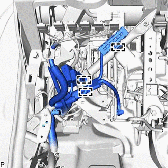
Disengage the 3 clamps.
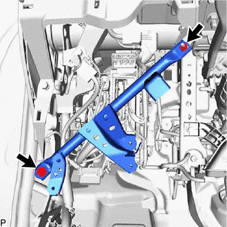
Remove the bolt, nut and No. 3 instrument panel to cowl brace sub-assembly.
4.REMOVE POWER DISTRIBUTION BOX ASSEMBLY WITH MAIN BODY ECU
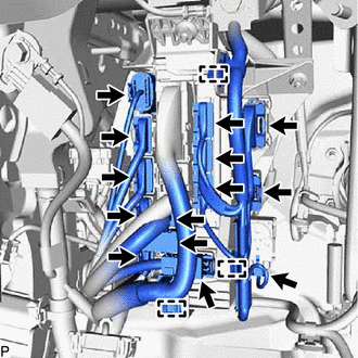
Disconnect each connector.
Disengage the 3 clamps.
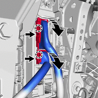

|
Remove in this Direction |
Disengage the 2 claws and pull down the 2 lock levers to disconnect the 2 connectors as shown in the illustration.
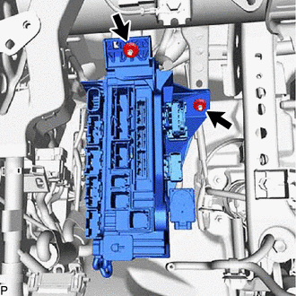
Remove the 2 nuts.
Pull out the power distribution box assembly with main body ECU.
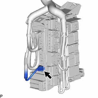
Disconnect the connector.

Disengage the clamp.

|
|
Remove in this Direction |
Disengage the 2 claws and raise the 2 lock levers to disconnect the 2 connectors as shown in the illustration.
Disengage the 3 claws as shown in the illustration to remove the power distribution box assembly with main body ECU.

|
|
Remove in this Direction | - | - |
82673C
5.REMOVE JUNCTION BLOCK BRACKET
Using a screwdriver with its tip wrapped with protective tape, disengage the 2 claws to remove the junction block bracket.
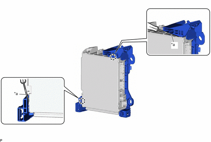
| *a | Protective Tape | - | - |
6.REMOVE MAIN BODY ECU (MULTIPLEX NETWORK BODY ECU)
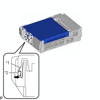
| *1 | Power Distribution Box Assembly |
| *2 | Main Body ECU (Multiplex Network Body ECU) |

|
Press in this Direction |
Press the claw of the power distribution box assembly as shown in the illustration to release the lock.
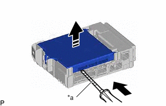
| *a | Protective Tape |
|
|
Insert in this Direction |
|
|
Remove in this Direction |
With the power distribution box assembly lock released, insert a screwdriver with its tip wrapped with protective tape horizontally between the main body ECU (multiplex network body ECU) and power distribution box assembly.
- NOTICE:
- ·
Use a screwdriver with a diameter between 5.0 mm (0.197 in.) and 6.3 mm (0.248 in.) and a length of approximately 90 mm (3.54 in.).
·Do not insert the screwdriver under the connector socket of the main body ECU (multiplex network body ECU).
Using the screwdriver, carefully raise the main body ECU (multiplex network body ECU) to the position where the connector becomes disconnected.
- NOTICE:
-
Do not twist the screwdriver to raise the main body ECU (multiplex network body ECU).
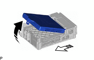
|
|
Remove in this Direction (1) |

|
Remove in this Direction (2) |
Raise the main body ECU (multiplex network body ECU) as shown by the arrow (1), and then pull it out as shown by the arrow (2) in the illustration.
- NOTICE:
-
Do not touch the main body ECU (multiplex network body ECU) connector.