NETWORKING CAN COMMUNICATION SYSTEM(for GTMC Made HV Model) TERMINALS OF ECU
- NOTICE:
- ·
Before measuring the resistance of the CAN bus, turn the power switch off and leave the vehicle for 1 minute or more without operating the key or any switches, or opening or closing the doors. After that, disconnect the cable from the negative (-) auxiliary battery terminal and leave the vehicle for 10 minutes or more before measuring the resistance.
·This section describes the standard values for all CAN related components.
- HINT:
- ·
When disconnecting and reconnecting the auxiliary battery, there is an automatic learning function that completes learning when the respective system is used.
·The systems (ECUs and sensors) that use CAN communication vary depending on the vehicle and optional equipment. Check which systems (ECUs and sensors) are installed to the vehicle.
·Operating the power switch, any other switches or a door triggers related ECU and sensor communication on the CAN. This communication will cause the resistance value to change.
·Even after DTCs are cleared, if a DTC is stored again after driving the vehicle for a while, the malfunction may be occurring due to vibration of the vehicle. In such a case, wiggling the ECUs or wire harness while performing the inspection below may help determine the cause of the malfunction.
NO. 1 CAN JUNCTION CONNECTOR
Check the No. 1 CAN junction connector.
Connection diagram
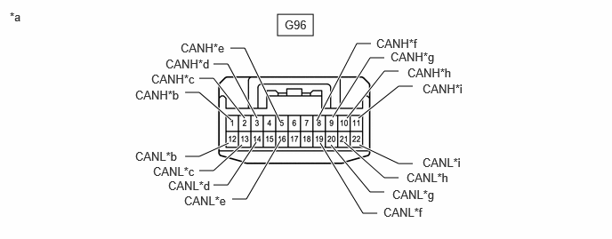
| *a | Front view of wire harness connector
(to No. 1 CAN Junction Connector) |
*b | for No. 7 CAN Junction Connector |
| *c | for Certification ECU (Smart Key ECU Assembly) | *d | for Central Gateway ECU (Network Gateway ECU) |
| *e | for Air Conditioning Amplifier Assembly | *f | for Airbag ECU Assembly |
| *g | for No. 10 CAN Junction Connector | *h | for Central Gateway ECU (Network Gateway ECU) |
| *i | for Steering Sensor | - | - |
Check the connection diagram of the components which are connected to the No. 1 CAN junction connector.
| Terminal No. (Symbol) | Wiring Color | Connected to |
|---|---|---|
| G96-1 (CANH) | P | No. 7 CAN junction connector |
| G96-12 (CANL) | W | |
| G96-2 (CANH) | G | Certification ECU (smart key ECU assembly) |
| G96-13 (CANL) | W | |
| G96-3 (CANH) | LG | Central gateway ECU (network gateway ECU) |
| G96-14 (CANL) | W | |
| G96-5 (CANH) | SB | Air conditioning amplifier assembly |
| G96-16 (CANL) | W | |
| G96-8 (CANH) | R | Airbag ECU assembly |
| G96-19 (CANL) | W | |
| G96-9 (CANH) | SB | No. 10 CAN junction connector |
| G96-20 (CANL) | W | |
| G96-10 (CANH) | G | Central gateway ECU (network gateway ECU) |
| G96-21 (CANL) | W | |
| G96-11 (CANH) | G | Steering sensor |
| G96-22 (CANL) | W |
NO. 2 CAN JUNCTION CONNECTOR
Check the No. 2 CAN junction connector.
Connection diagram

| *a | Front view of wire harness connector
(to No. 2 CAN Junction Connector) |
*b | for Millimeter Wave Radar Sensor Assembly |
| *c | for No. 8 CAN Junction Connector | *d | for Parking Assist ECU (w/ Panoramic View Monitor System) |
| *e | for Forward Recognition Camera | *f | for Clearance Warning ECU Assembly |
| *g | for Central Gateway ECU (Network Gateway ECU) | - | - |
Check the connection diagram of the components which are connected to the No. 2 CAN junction connector.
| Terminal No. (Symbol) | Wiring Color | Connected to |
|---|---|---|
|
*: w/ Panoramic View Monitor System |
||
| G102-2 (CANH) | R | Millimeter wave radar sensor assembly |
| G102-12 (CANL) | W | |
| G102-3 (CANH) | B | No. 8 CAN junction connector |
| G102-13 (CANL) | W | |
| G102-5 (CANH) | GR | Parking assist ECU* |
| G102-15 (CANL) | W | |
| G102-6 (CANH) | L | Forward recognition camera |
| G102-16 (CANL) | B | |
| G102-7 (CANH) | L | Clearance warning ECU assembly |
| G102-17 (CANL) | W | |
| G102-8 (CANH) | P | Central gateway ECU (network gateway ECU) |
| G102-18 (CANL) | W | |
NO. 3 CAN JUNCTION CONNECTOR
Check the No. 3 CAN junction connector.
Connection diagram
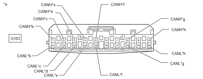
| *a | Front view of wire harness connector
(to No. 3 CAN Junction Connector) |
*b | for Central Gateway ECU (Network Gateway ECU) |
| *c | for Inverter with Converter Assembly (for AWD) | *d | for ECM |
| *e | for Inverter with Converter Assembly | *f | for Hybrid Vehicle Control ECU Assembly |
| *g | for Vehicle Approaching Speaker Controller | *h | for Battery ECU Assembly |
Check the connection diagram of the components which are connected to the No. 3 CAN junction connector.
| Terminal No. (Symbol) | Wiring Color | Connected to |
|---|---|---|
|
*: for AWD |
||
| G103-1 (CANH) | SB | Central gateway ECU (network gateway ECU) |
| G103-11 (CANL) | W | |
| G103-2 (CANH)* | LG | Inverter with converter assembly |
| G103-12 (CANL)* | W | |
| G103-3 (CANH) | G | ECM |
| G103-13 (CANL) | W | |
| G103-4 (CANH) | V | Inverter with converter assembly |
| G103-14 (CANL) | W | |
| G103-5 (CANH) | L | Hybrid vehicle control ECU assembly |
| G103-15 (CANL) | W | |
| G103-8 (CANH) | P | Vehicle approaching speaker controller |
| G103-18 (CANL) | W | |
| G103-10 (CANH) | V | Battery ECU assembly |
| G103-20 (CANL) | W | |
NO. 4 CAN JUNCTION CONNECTOR
Check the No. 4 CAN junction connector.
Connection diagram
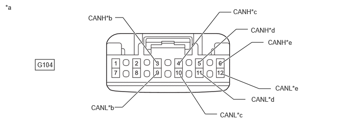
| *a | Front view of wire harness connector
(to No. 4 CAN Junction Connector) |
*b | for Hybrid Vehicle Control ECU Assembly |
| *c | for Brake Booster with Master Cylinder Assembly (No. 1 Skid Control ECU) | *d | for Brake Actuator Assembly (No. 2 Skid Control ECU) |
| *e | for ECM | - | - |
Check the connection diagram of the components which are connected to the No. 4 CAN junction connector.
| Terminal No. (Symbol) | Wiring Color | Connected to |
|---|---|---|
| G104-3 (CANH) | G | Hybrid vehicle control ECU assembly |
| G104-9 (CANL) | W | |
| G104-4 (CANH) | LG | Brake booster with master cylinder assembly (No. 1 skid control ECU) |
| G104-10 (CANL) | W | |
| G104-5 (CANH) | L | Brake actuator assembly (No. 2 skid control ECU) |
| G104-11 (CANL) | W | |
| G104-6 (CANH) | P | ECM |
| G104-12 (CANL) | W |
NO. 5 CAN JUNCTION CONNECTOR
Check the No. 5 CAN junction connector.
Connection diagram
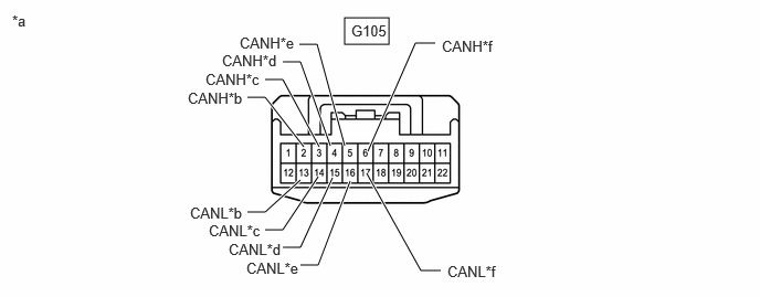
| *a | Front view of wire harness connector
(to No. 5 CAN Junction Connector) |
*b | for Central Gateway ECU (Network Gateway ECU) |
| *c | for Telephone Transceiver | *d | for Combination Meter Assembly |
| *e | ·
for Radio and Display Receiver Assembly (w/o Navigation System) ·
for Navigation Receiver Assembly (w/ Navigation System) |
*f | for Meter Mirror Sub-assembly (w/ Headup Display System) |
Check the connection diagram of the components which are connected to the No. 5 CAN junction connector.
| Terminal No. (Symbol) | Wiring Color | Connected to |
|---|---|---|
|
*1: w/o Navigation System *2: w/ Navigation System *3: w/ Headup Display System |
||
| G105-2 (CANH) | B | Central gateway ECU (network gateway ECU) |
| G105-13 (CANL) | W | |
| G105-3 (CANH) | R | Telephone transceiver |
| G105-14 (CANL) | W | |
| G105-4 (CANH) | L | Combination meter assembly |
| G105-15 (CANL) | W | |
| G105-5 (CANH) | B | ·
Radio and display receiver assembly*1 ·
Navigation receiver assembly*2 |
| G105-16 (CANL) | W | |
| G105-6 (CANH) | LG | Meter mirror sub-assembly*3 |
| G105-17 (CANL) | W | |
NO. 6 CAN JUNCTION CONNECTOR
Check the No. 6 CAN junction connector.
Connection diagram
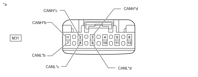
| *a | Front view of wire harness connector
(to No. 6 CAN Junction Connector) |
*b | for Tire Pressure Warning ECU and Receiver |
| *c | for No. 2 CAN Junction Terminal | *d | for Central Gateway ECU (Network Gateway ECU) |
Check the connection diagram of the components which are connected to the No. 6 CAN junction connector.
| Terminal No. (Symbol) | Wiring Color | Connected to |
|---|---|---|
| M31-1 (CANH) | L | Tire pressure warning ECU and receiver |
| M31-7 (CANL) | W | |
| M31-2 (CANH) | B | No. 2 CAN junction terminal |
| M31-8 (CANL) | W | |
| M31-3 (CANH) | G | Central gateway ECU (network gateway ECU) |
| M31-9 (CANL) | W |
NO. 7 CAN JUNCTION CONNECTOR
Check the No. 7 CAN junction connector.
Connection diagram
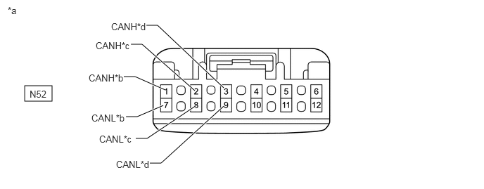
| *a | Front view of wire harness connector
(to No. 7 CAN Junction Connector) |
*b | for No. 1 CAN Junction Connector |
| *c | for Main Body ECU (Multiplex Network Body ECU) | *d | for Multiplex Network Door ECU (w/ Power Back Door System) |
Check the connection diagram of the components which are connected to the No. 7 CAN junction connector.
| Terminal No. (Symbol) | Wiring Color | Connected to |
|---|---|---|
|
*: w/ Power Back Door System |
||
| N52-1 (CANH) | B | No. 1 CAN junction connector |
| N52-7 (CANL) | W | |
| N52-2 (CANH) | LG | Main body ECU (multiplex network body ECU) |
| N52-8 (CANL) | W | |
| N52-3 (CANH) | L | Multiplex network door ECU* |
| N52-9 (CANL) | W | |
NO. 8 CAN JUNCTION CONNECTOR
Check the No. 8 CAN junction connector.
Connection diagram
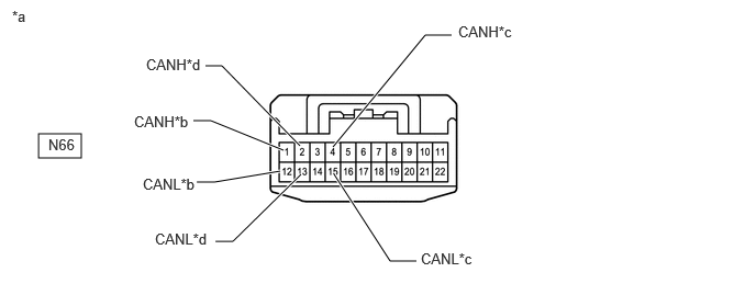
| *a | Front view of wire harness connector
(to No. 8 CAN Junction Connector) |
*b | for No. 2 CAN Junction Connector |
| *c | for No. 1 CAN Junction Terminal | *d | for Blind Spot Monitor Sensor LH (w/ Blind Spot Monitor System) |
Check the connection diagram of the components which are connected to the No. 8 CAN junction connector.
| Terminal No. (Symbol) | Wiring Color | Connected to |
|---|---|---|
|
*: w/ Blind Spot Monitor System |
||
| N66-1 (CANH) | SB | No. 2 CAN junction connector |
| N66-12 (CANL) | W | |
| N66-2 (CANH) | BE | Blind spot monitor sensor LH* |
| N66-13 (CANL) | W | |
| N66-4 (CANH) | G | No. 1 CAN junction terminal |
| N66-15 (CANL) | W | |
NO. 10 CAN JUNCTION CONNECTOR
Check the No. 10 CAN junction connector.
Connection diagram
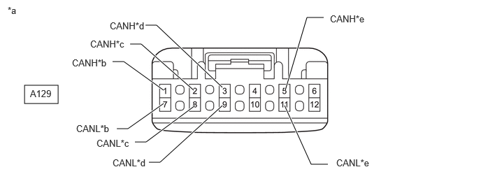
| *a | Front view of wire harness connector
(to No. 10 CAN Junction Connector) |
*b | for Rack and Pinion Power Steering Gear Assembly |
| *c | for Brake Actuator Assembly (No. 2 Skid Control ECU) | *d | for Brake Booster with Master Cylinder Assembly (No. 1 Skid Control ECU) |
| *e | for No. 1 CAN Junction Connector | - | - |
Check the connection diagram of the components which are connected to the No. 4 CAN junction connector.
| Terminal No. (Symbol) | Wiring Color | Connected to |
|---|---|---|
| A129-1 (CANH) | G | Rack and pinion power steering gear assembly |
| A129-7 (CANL) | W | |
| A129-2 (CANH) | V | Brake actuator assembly (No. 2 skid control ECU) |
| A129-8 (CANL) | W | |
| A129-3 (CANH) | Y | Brake booster with master cylinder assembly (No. 1 skid control ECU) |
| A129-9 (CANL) | W | |
| A129-5 (CANH) | SB | No. 1 CAN junction connector |
| A129-11 (CANL) | W |
NO. 1 CAN JUNCTION TERMINAL
Check the No. 1 CAN junction terminal.
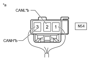
| *a | Rear view of wire harness connector
(to No. 1 CAN Junction Terminal) |
| *b | for No. 8 CAN Junction Connector |
Connection diagram
Check the connection diagram of the components which are connected to the No. 1 CAN junction terminal.
| Terminal No. (Symbol) | Wiring Color | Connected to |
|---|---|---|
| N54-3 (CANH) | G | No. 8 CAN junction connector |
| N54-2 (CANL) | W |
NO. 2 CAN JUNCTION TERMINAL
Check the No. 2 CAN junction terminal.
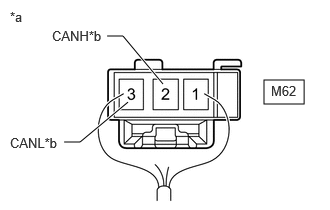
| *a | Rear view of wire harness connector
(to No. 2 CAN Junction Terminal) |
| *b | for No. 6 CAN Junction Connector |
Connection diagram
Check the connection diagram of the components which are connected to the No. 2 CAN junction terminal.
| Terminal No. (Symbol) | Wiring Color | Connected to |
|---|---|---|
| M62-2 (CANH) | B | No. 6 CAN junction connector |
| M62-3 (CANL) | W |
DLC3
Disconnect the cable from the negative (-) auxiliary battery terminal.
Measure the resistance according to the value(s) in the table below.
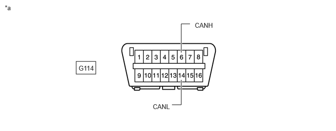
| *a | Front view of DLC3 | - | - |
- Standard Resistance:
Terminal No. (Symbol) Terminal Description Condition Specified Condition G114-6 (CANH) - G114-14 (CANL) HIGH-level CAN bus line - LOW-level CAN bus line Cable disconnected from negative (-) auxiliary battery terminal 54 to 69 Ω G114-6 (CANH) - Body ground HIGH-level CAN bus line - Body ground Cable disconnected from negative (-) auxiliary battery terminal 200 Ω or higher G114-14 (CANL) - Body ground LOW-level CAN bus line - Body ground Cable disconnected from negative (-) auxiliary battery terminal 200 Ω or higher G114-6 (CANH) - Positive (+) auxiliary battery terminal HIGH-level CAN bus line - Auxiliary battery positive (+) Cable disconnected from negative (-) auxiliary battery terminal 6 kΩ or higher G114-14 (CANL) - Positive (+) auxiliary battery terminal LOW-level CAN bus line - Auxiliary battery positive (+) Cable disconnected from negative (-) auxiliary battery terminal 6 kΩ or higher
CENTRAL GATEWAY ECU (NETWORK GATEWAY ECU)
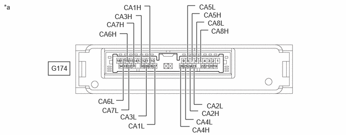
| *a | Component without harness connected
(Central Gateway ECU [Network Gateway ECU]) |
- | - |
Disconnect the cable from the negative (-) auxiliary battery terminal.
Disconnect the central gateway ECU (network gateway ECU) connector.
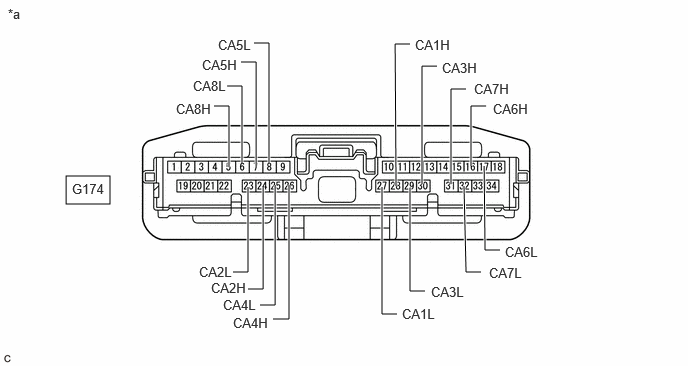
| *a | Front view of wire harness connector
(to Central Gateway ECU [Network Gateway ECU]) |
- | - |
Measure the resistance according to the value(s) in the table below.
- Standard Resistance:
V Bus Branch Lines (DLC3 - Central Gateway ECU [Network Gateway ECU]) Terminal No. (Symbol) Terminal Description Condition Specified Condition G174-16 (CA6H) - G174-17 (CA6L) HIGH-level CAN bus line - LOW-level CAN bus line Cable disconnected from negative (-) auxiliary battery terminal 1 MΩ or higher G174-16 (CA6H) - Body ground HIGH-level CAN bus line - Body ground Cable disconnected from negative (-) auxiliary battery terminal 200 Ω or higher G174-17 (CA6L) - Body ground LOW-level CAN bus line - Body ground Cable disconnected from negative (-) auxiliary battery terminal 200 Ω or higher G174-16 (CA6H) - Positive (+) auxiliary battery terminal HIGH-level CAN bus line - Auxiliary battery positive (+) Cable disconnected from negative (-) auxiliary battery terminal 6 kΩ or higher G174-17 (CA6L) - Positive (+) auxiliary battery terminal LOW-level CAN bus line - Auxiliary battery positive (+) Cable disconnected from negative (-) auxiliary battery terminal 6 kΩ or higher
Bus 1 Main Lines Terminal No. (Symbol) Terminal Description Condition Specified Condition G174-28 (CA1H) - G174-27 (CA1L) HIGH-level CAN bus line - LOW-level CAN bus line Cable disconnected from negative (-) auxiliary battery terminal 108 to 132 Ω G174-28 (CA1H) - Body ground HIGH-level CAN bus line - Body ground Cable disconnected from negative (-) auxiliary battery terminal 200 Ω or higher G174-27 (CA1L) - Body ground LOW-level CAN bus line - Body ground Cable disconnected from negative (-) auxiliary battery terminal 200 Ω or higher G174-28 (CA1H) - Positive (+) auxiliary battery terminal HIGH-level CAN bus line - Auxiliary battery positive (+) Cable disconnected from negative (-) auxiliary battery terminal 6 kΩ or higher G174-27 (CA1L) - Positive (+) auxiliary battery terminal LOW-level CAN bus line - Auxiliary battery positive (+) Cable disconnected from negative (-) auxiliary battery terminal 6 kΩ or higher
Bus 2 Main Lines Terminal No. (Symbol) Terminal Description Condition Specified Condition G174-26 (CA4H) - G174-25 (CA4L) HIGH-level CAN bus line - LOW-level CAN bus line Cable disconnected from negative (-) auxiliary battery terminal 108 to 132 Ω G174-26 (CA4H) - Body ground HIGH-level CAN bus line - Body ground Cable disconnected from negative (-) auxiliary battery terminal 200 Ω or higher G174-25 (CA4L) - Body ground LOW-level CAN bus line - Body ground Cable disconnected from negative (-) auxiliary battery terminal 200 Ω or higher G174-26 (CA4H) - Positive (+) auxiliary battery terminal HIGH-level CAN bus line - Auxiliary battery positive (+) Cable disconnected from negative (-) auxiliary battery terminal 6 kΩ or higher G174-25 (CA4L) - Positive (+) auxiliary battery terminal LOW-level CAN bus line - Auxiliary battery positive (+) Cable disconnected from negative (-) auxiliary battery terminal 6 kΩ or higher
Bus 3 Main Lines Terminal No. (Symbol) Terminal Description Condition Specified Condition G174-30 (CA3H) - G174-29 (CA3L) HIGH-level CAN bus line - LOW-level CAN bus line Cable disconnected from negative (-) auxiliary battery terminal 108 to 132 Ω G174-30 (CA3H) - Body ground HIGH-level CAN bus line - Body ground Cable disconnected from negative (-) auxiliary battery terminal 200 Ω or higher G174-29 (CA3L) - Body ground LOW-level CAN bus line - Body ground Cable disconnected from negative (-) auxiliary battery terminal 200 Ω or higher G174-30 (CA3H) - Positive (+) auxiliary battery terminal HIGH-level CAN bus line - Auxiliary battery positive (+) Cable disconnected from negative (-) auxiliary battery terminal 6 kΩ or higher G174-29 (CA3L) - Positive (+) auxiliary battery terminal LOW-level CAN bus line - Auxiliary battery positive (+) Cable disconnected from negative (-) auxiliary battery terminal 6 kΩ or higher
Bus 4 Main Lines Terminal No. (Symbol) Terminal Description Condition Specified Condition G174-24 (CA2H) - G174-23 (CA2L) HIGH-level CAN bus line - LOW-level CAN bus line Cable disconnected from negative (-) auxiliary battery terminal 108 to 132 Ω G174-24 (CA2H) - Body ground HIGH-level CAN bus line - Body ground Cable disconnected from negative (-) auxiliary battery terminal 200 Ω or higher G174-23 (CA2L) - Body ground LOW-level CAN bus line - Body ground Cable disconnected from negative (-) auxiliary battery terminal 200 Ω or higher G174-24 (CA2H) - Positive (+) auxiliary battery terminal HIGH-level CAN bus line - Auxiliary battery positive (+) Cable disconnected from negative (-) auxiliary battery terminal 6 kΩ or higher G174-23 (CA2L) - Positive (+) auxiliary battery terminal LOW-level CAN bus line - Auxiliary battery positive (+) Cable disconnected from negative (-) auxiliary battery terminal 6 kΩ or higher
Bus 5 Main Lines Terminal No. (Symbol) Terminal Description Condition Specified Condition G174-7 (CA5H) - G174-8 (CA5L) HIGH-level CAN bus line - LOW-level CAN bus line Cable disconnected from negative (-) auxiliary battery terminal 108 to 132 Ω G174-7 (CA5H) - Body ground HIGH-level CAN bus line - Body ground Cable disconnected from negative (-) auxiliary battery terminal 200 Ω or higher G174-8 (CA5L) - Body ground LOW-level CAN bus line - Body ground Cable disconnected from negative (-) auxiliary battery terminal 200 Ω or higher G174-7 (CA5H) - Positive (+) auxiliary battery terminal HIGH-level CAN bus line - Auxiliary battery positive (+) Cable disconnected from negative (-) auxiliary battery terminal 6 kΩ or higher G174-8 (CA5L) - Positive (+) auxiliary battery terminal LOW-level CAN bus line - Auxiliary battery positive (+) Cable disconnected from negative (-) auxiliary battery terminal 6 kΩ or higher
Bus 6 Main Lines Terminal No. (Symbol) Terminal Description Condition Specified Condition G174-31 (CA7H) - G174-32 (CA7L) HIGH-level CAN bus line - LOW-level CAN bus line Cable disconnected from negative (-) auxiliary battery terminal 108 to 132 Ω G174-31 (CA7H) - Body ground HIGH-level CAN bus line - Body ground Cable disconnected from negative (-) auxiliary battery terminal 200 Ω or higher G174-32 (CA7L) - Body ground LOW-level CAN bus line - Body ground Cable disconnected from negative (-) auxiliary battery terminal 200 Ω or higher G174-31 (CA7H) - Positive (+) auxiliary battery terminal HIGH-level CAN bus line - Auxiliary battery positive (+) Cable disconnected from negative (-) auxiliary battery terminal 6 kΩ or higher G174-32 (CA7L) - Positive (+) auxiliary battery terminal LOW-level CAN bus line - Auxiliary battery positive (+) Cable disconnected from negative (-) auxiliary battery terminal 6 kΩ or higher
Bus 7 Main Lines Terminal No. (Symbol) Terminal Description Condition Specified Condition G174-5 (CA8H) - G174-6 (CA8L) HIGH-level CAN bus line - LOW-level CAN bus line Cable disconnected from negative (-) auxiliary battery terminal 108 to 132 Ω G174-5 (CA8H) - Body ground HIGH-level CAN bus line - Body ground Cable disconnected from negative (-) auxiliary battery terminal 200 Ω or higher G174-6 (CA8L) - Body ground LOW-level CAN bus line - Body ground Cable disconnected from negative (-) auxiliary battery terminal 200 Ω or higher G174-5 (CA8H) - Positive (+) auxiliary battery terminal HIGH-level CAN bus line - Auxiliary battery positive (+) Cable disconnected from negative (-) auxiliary battery terminal 6 kΩ or higher G174-6 (CA8L) - Positive (+) auxiliary battery terminal LOW-level CAN bus line - Auxiliary battery positive (+) Cable disconnected from negative (-) auxiliary battery terminal 6 kΩ or higher
ECM
Refer to Terminals of ECU.
for A25B-FXS: Click hereEngine / Hybrid System>A25B-FXS (ENGINE CONTROL)>SFI SYSTEM>TERMINALS OF ECM202405,999999,_51,_083340,_0402276,RM100000002IZX6,
for A25D-FXS: Click hereEngine / Hybrid System>A25D-FXS (ENGINE CONTROL)>SFI SYSTEM>TERMINALS OF ECM202405,999999,_51,_103786,_0477830,RM100000002J02O,
Disconnect the cable from the negative (-) auxiliary battery terminal.
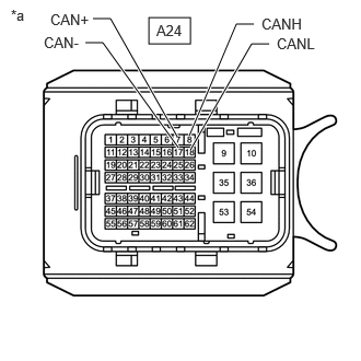
| *a | Front view of wire harness connector
(to ECM) |
Disconnect the ECM connector.
Measure the resistance according to the value(s) in the table below.
- Standard Resistance:
Bus 2 Main Lines Terminal No. (Symbol) Terminal Description Condition Specified Condition A24-8 (CANH) - A24-18 (CANL) HIGH-level CAN bus line - LOW-level CAN bus line Cable disconnected from negative (-) auxiliary battery terminal 108 to 132 Ω A24-8 (CANH) - Body ground HIGH-level CAN bus line - Body ground Cable disconnected from negative (-) auxiliary battery terminal 200 Ω or higher A24-18 (CANL) - Body ground LOW-level CAN bus line - Body ground Cable disconnected from negative (-) auxiliary battery terminal 200 Ω or higher A24-8 (CANH) - Positive (+) auxiliary battery terminal HIGH-level CAN bus line - Auxiliary battery positive (+) Cable disconnected from negative (-) auxiliary battery terminal 6 kΩ or higher A24-18 (CANL) - Positive (+) auxiliary battery terminal LOW-level CAN bus line - Auxiliary battery positive (+) Cable disconnected from negative (-) auxiliary battery terminal 6 kΩ or higher
Powertrain Local Bus Branch Lines Terminal No. (Symbol) Terminal Description Condition Specified Condition A24-7 (CAN+) - A24-17 (CAN-) HIGH-level CAN bus line - LOW-level CAN bus line Cable disconnected from negative (-) auxiliary battery terminal 54 to 69 Ω A24-7 (CAN+) - Body ground HIGH-level CAN bus line - Body ground Cable disconnected from negative (-) auxiliary battery terminal 200 Ω or higher A24-17 (CAN-) - Body ground LOW-level CAN bus line - Body ground Cable disconnected from negative (-) auxiliary battery terminal 200 Ω or higher A24-7 (CAN+) - Positive (+) auxiliary battery terminal HIGH-level CAN bus line - Auxiliary battery positive (+) Cable disconnected from negative (-) auxiliary battery terminal 6 kΩ or higher A24-17 (CAN-) - Positive (+) auxiliary battery terminal LOW-level CAN bus line - Auxiliary battery positive (+) Cable disconnected from negative (-) auxiliary battery terminal 6 kΩ or higher
HYBRID VEHICLE CONTROL ECU ASSEMBLY
Refer to Terminals of ECU.
Disconnect the cable from the negative (-) auxiliary battery terminal.
Disconnect the hybrid vehicle control ECU assembly connector.
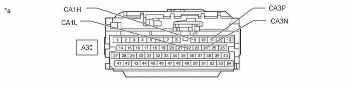
| *a | Front view of wire harness connector
(to Hybrid Vehicle Control ECU Assembly) |
- | - |
Measure the resistance according to the value(s) in the table below.
- Standard Resistance:
Bus 2 Branch Lines Terminal No. (Symbol) Terminal Description Condition Specified Condition A30-9 (CA1H) - A30-22 (CA1L) HIGH-level CAN bus line - LOW-level CAN bus line Cable disconnected from negative (-) auxiliary battery terminal 54 to 69 Ω A30-9 (CA1H) - Body ground HIGH-level CAN bus line - Body ground Cable disconnected from negative (-) auxiliary battery terminal 200 Ω or higher A30-22 (CA1L) - Body ground LOW-level CAN bus line - Body ground Cable disconnected from negative (-) auxiliary battery terminal 200 Ω or higher A30-9 (CA1H) - Positive (+) auxiliary battery terminal HIGH-level CAN bus line - Auxiliary battery positive (+) Cable disconnected from negative (-) auxiliary battery terminal 6 kΩ or higher A30-22 (CA1L) - Positive (+) auxiliary battery terminal LOW-level CAN bus line - Auxiliary battery positive (+) Cable disconnected from negative (-) auxiliary battery terminal 6 kΩ or higher
Powertrain Local Bus Main Lines Terminal No. (Symbol) Terminal Description Condition Specified Condition A30-24 (CA3P) - A30-11 (CA3N) HIGH-level CAN bus line - LOW-level CAN bus line Cable disconnected from negative (-) auxiliary battery terminal 108 to 132 Ω A30-24 (CA3P) - Body ground HIGH-level CAN bus line - Body ground Cable disconnected from negative (-) auxiliary battery terminal 200 Ω or higher A30-11 (CA3N) - Body ground LOW-level CAN bus line - Body ground Cable disconnected from negative (-) auxiliary battery terminal 200 Ω or higher A30-24 (CA3P) - Positive (+) auxiliary battery terminal HIGH-level CAN bus line - Auxiliary battery positive (+) Cable disconnected from negative (-) auxiliary battery terminal 6 kΩ or higher A30-11 (CA3N) - Positive (+) auxiliary battery terminal LOW-level CAN bus line - Auxiliary battery positive (+) Cable disconnected from negative (-) auxiliary battery terminal 6 kΩ or higher
INVERTER WITH CONVERTER ASSEMBLY
Refer to Terminals of ECU.
Disconnect the cable from the negative (-) auxiliary battery terminal.
Disconnect the inverter with converter assembly connector.
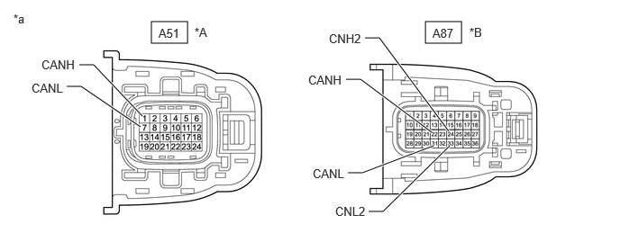
| *A | for 2WD | *B | for AWD |
| *a | Front view of wire harness connector
(to Inverter with Converter Assembly) |
- | - |
Measure the resistance according to the value(s) in the table below.
- Standard Resistance:
for 2WD Terminal No. (Symbol) Terminal Description Condition Specified Condition A51-1 (CANH) - A51-7 (CANL) HIGH-level CAN bus line - LOW-level CAN bus line Cable disconnected from negative (-) auxiliary battery terminal 54 to 69 Ω A51-1 (CANH) - Body ground HIGH-level CAN bus line - Body ground Cable disconnected from negative (-) auxiliary battery terminal 200 Ω or higher A51-7 (CANL) - Body ground LOW-level CAN bus line - Body ground Cable disconnected from negative (-) auxiliary battery terminal 200 Ω or higher A51-1 (CANH) - Positive (+) auxiliary battery terminal HIGH-level CAN bus line - Auxiliary battery positive (+) Cable disconnected from negative (-) auxiliary battery terminal 6 kΩ or higher A51-7 (CANL) - Positive (+) auxiliary battery terminal LOW-level CAN bus line - Auxiliary battery positive (+) Cable disconnected from negative (-) auxiliary battery terminal 6 kΩ or higher
for AWD Terminal No. (Symbol) Terminal Description Condition Specified Condition A87-22 (CANH) - A87-31 (CANL) HIGH-level CAN bus line - LOW-level CAN bus line Cable disconnected from negative (-) auxiliary battery terminal 54 to 69 Ω A87-22 (CANH) - Body ground HIGH-level CAN bus line - Body ground Cable disconnected from negative (-) auxiliary battery terminal 200 Ω or higher A87-31 (CANL) - Body ground LOW-level CAN bus line - Body ground Cable disconnected from negative (-) auxiliary battery terminal 200 Ω or higher A87-22 (CANH) - Positive (+) auxiliary battery terminal HIGH-level CAN bus line - Auxiliary battery positive (+) Cable disconnected from negative (-) auxiliary battery terminal 6 kΩ or higher A87-31 (CANL) - Positive (+) auxiliary battery terminal LOW-level CAN bus line - Auxiliary battery positive (+) Cable disconnected from negative (-) auxiliary battery terminal 6 kΩ or higher A87-24 (CNH2) - A87-33 (CNL2) HIGH-level CAN bus line - LOW-level CAN bus line Cable disconnected from negative (-) auxiliary battery terminal 54 to 69 Ω A87-24 (CNH2) - Body ground HIGH-level CAN bus line - Body ground Cable disconnected from negative (-) auxiliary battery terminal 200 Ω or higher A87-33 (CNL2) - Body ground LOW-level CAN bus line - Body ground Cable disconnected from negative (-) auxiliary battery terminal 200 Ω or higher A87-24 (CNH2) - Positive (+) auxiliary battery terminal HIGH-level CAN bus line - Auxiliary battery positive (+) Cable disconnected from negative (-) auxiliary battery terminal 6 kΩ or higher A87-33 (CNL2) - Positive (+) auxiliary battery terminal LOW-level CAN bus line - Auxiliary battery positive (+) Cable disconnected from negative (-) auxiliary battery terminal 6 kΩ or higher
BRAKE BOOSTER WITH MASTER CYLINDER ASSEMBLY (NO. 1 SKID CONTROL ECU)
Refer to Terminals of ECU.
Disconnect the cable from the negative (-) auxiliary battery terminal.
Disconnect the brake booster with master cylinder assembly (No. 1 skid control ECU) connector.
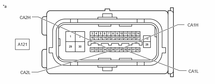
| *a | Front view of wire harness connector
(to Brake Booster with Master Cylinder Assembly [No. 1 Skid Control ECU]) |
- | - |
Measure the resistance according to the value(s) in the table below.
- Standard Resistance:
Bus 4 Branch Lines Terminal No. (Symbol) Terminal Description Condition Specified Condition A121-38 (CA1H) - A121-39 (CA1L) HIGH-level CAN bus line - LOW-level CAN bus line Cable disconnected from negative (-) auxiliary battery terminal 54 to 69 Ω A121-38 (CA1H) - Body ground HIGH-level CAN bus line - Body ground Cable disconnected from negative (-) auxiliary battery terminal 200 Ω or higher A121-39 (CA1L) - Body ground LOW-level CAN bus line - Body ground Cable disconnected from negative (-) auxiliary battery terminal 200 Ω or higher A121-38 (CA1H) - Positive (+) auxiliary battery terminal HIGH-level CAN bus line - Auxiliary battery positive (+) Cable disconnected from negative (-) auxiliary battery terminal 6 kΩ or higher A121-39 (CA1L) - Positive (+) auxiliary battery terminal LOW-level CAN bus line - Auxiliary battery positive (+) Cable disconnected from negative (-) auxiliary battery terminal 6 kΩ or higher
Powertrain Local Bus Branch Lines Terminal No. (Symbol) Terminal Description Condition Specified Condition A121-35 (CA2H) - A121-36 (CA2L) HIGH-level CAN bus line - LOW-level CAN bus line Cable disconnected from negative (-) auxiliary battery terminal 54 to 69 Ω A121-35 (CA2H) - Body ground HIGH-level CAN bus line - Body ground Cable disconnected from negative (-) auxiliary battery terminal 200 Ω or higher A121-36 (CA2L) - Body ground LOW-level CAN bus line - Body ground Cable disconnected from negative (-) auxiliary battery terminal 200 Ω or higher A121-35 (CA2H) - Positive (+) auxiliary battery terminal HIGH-level CAN bus line - Auxiliary battery positive (+) Cable disconnected from negative (-) auxiliary battery terminal 6 kΩ or higher A121-36 (CA2L) - Positive (+) auxiliary battery terminal LOW-level CAN bus line - Auxiliary battery positive (+) Cable disconnected from negative (-) auxiliary battery terminal 6 kΩ or higher
BRAKE ACTUATOR ASSEMBLY (NO. 2 SKID CONTROL ECU)
Refer to Terminals of ECU.
Disconnect the cable from the negative (-) auxiliary battery terminal.
Disconnect the brake actuator assembly (No. 2 skid control ECU) connector.
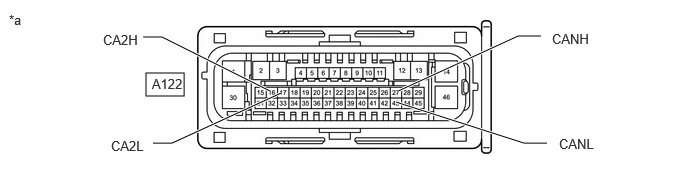
| *a | Front view of wire harness connector
(to Brake Actuator Assembly [No. 2 Skid Control ECU]) |
- | - |
Measure the resistance according to the value(s) in the table below.
- Standard Resistance:
Bus 4 Branch Lines Terminal No. (Symbol) Terminal Description Condition Specified Condition A122-27 (CANH) - A122-43 (CANL) HIGH-level CAN bus line - LOW-level CAN bus line Cable disconnected from negative (-) auxiliary battery terminal 54 to 69 Ω A122-27 (CANH) - Body ground HIGH-level CAN bus line - Body ground Cable disconnected from negative (-) auxiliary battery terminal 200 Ω or higher A122-43 (CANL) - Body ground LOW-level CAN bus line - Body ground Cable disconnected from negative (-) auxiliary battery terminal 200 Ω or higher A122-27 (CANH) - Positive (+) auxiliary battery terminal HIGH-level CAN bus line - Auxiliary battery positive (+) Cable disconnected from negative (-) auxiliary battery terminal 6 kΩ or higher A122-43 (CANL) - Positive (+) auxiliary battery terminal LOW-level CAN bus line - Auxiliary battery positive (+) Cable disconnected from negative (-) auxiliary battery terminal 6 kΩ or higher
Powertrain Local Bus Main Lines Terminal No. (Symbol) Terminal Description Condition Specified Condition A122-16 (CA2H) - A122-17 (CA2L) HIGH-level CAN bus line - LOW-level CAN bus line Cable disconnected from negative (-) auxiliary battery terminal 108 to 132 Ω A122-16 (CA2H) - Body ground HIGH-level CAN bus line - Body ground Cable disconnected from negative (-) auxiliary battery terminal 200 Ω or higher A122-17 (CA2L) - Body ground LOW-level CAN bus line - Body ground Cable disconnected from negative (-) auxiliary battery terminal 200 Ω or higher A122-16 (CA2H) - Positive (+) auxiliary battery terminal HIGH-level CAN bus line - Auxiliary battery positive (+) Cable disconnected from negative (-) auxiliary battery terminal 6 kΩ or higher A122-17 (CA2L) - Positive (+) auxiliary battery terminal LOW-level CAN bus line - Auxiliary battery positive (+) Cable disconnected from negative (-) auxiliary battery terminal 6 kΩ or higher
RACK AND PINION POWER STEERING GEAR ASSEMBLY
Refer to Terminals of ECU.
Disconnect the cable from the negative (-) auxiliary battery terminal.
Disconnect the rack and pinion power steering gear assembly connector.
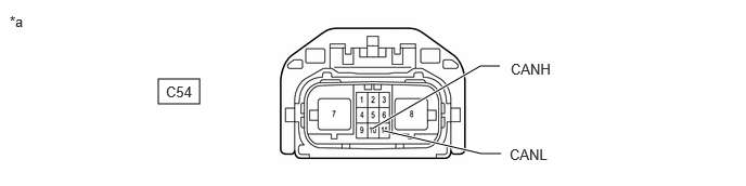
| *a | Front view of wire harness connector
(to Rack and Pinion Power Steering Gear Assembly (Power Steering ECU)) |
- | - |
Measure the resistance according to the value(s) in the table below.
- Standard Resistance:
Terminal No. (Symbol) Terminal Description Condition Specified Condition C54-10 (CANH) - C54-11 (CANL) HIGH-level CAN bus line - LOW-level CAN bus line Cable disconnected from negative (-) auxiliary battery terminal 108 to 132 Ω C54-10 (CANH) - Body ground HIGH-level CAN bus line - Body ground Cable disconnected from negative (-) auxiliary battery terminal 200 Ω or higher C54-11 (CANL) - Body ground LOW-level CAN bus line - Body ground Cable disconnected from negative (-) auxiliary battery terminal 200 Ω or higher C54-10 (CANH) - Positive (+) auxiliary battery terminal HIGH-level CAN bus line - Auxiliary battery positive (+) Cable disconnected from negative (-) auxiliary battery terminal 6 kΩ or higher C54-11 (CANL) - Positive (+) auxiliary battery terminal LOW-level CAN bus line - Auxiliary battery positive (+) Cable disconnected from negative (-) auxiliary battery terminal 6 kΩ or higher
STEERING SENSOR
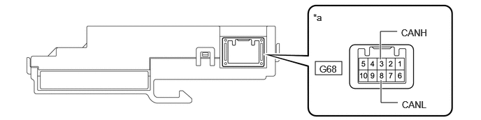
| *a | Component without harness connected
(Steering Sensor) |
- | - |
Disconnect the cable from the negative (-) auxiliary battery terminal.
Disconnect the steering sensor connector.
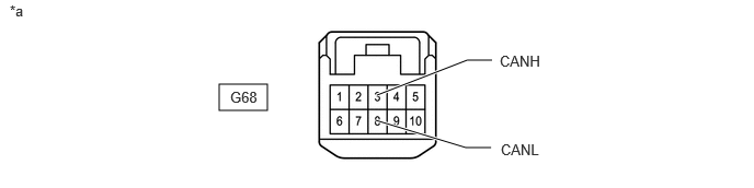
| *a | Front view of wire harness connector
(to Steering Sensor) |
- | - |
Measure the resistance according to the value(s) in the table below.
- Standard Resistance:
Terminal No. (Symbol) Terminal Description Condition Specified Condition G68-3 (CANH) - G68-8 (CANL) HIGH-level CAN bus line - LOW-level CAN bus line Cable disconnected from negative (-) auxiliary battery terminal 54 to 69 Ω G68-3 (CANH) - Body ground HIGH-level CAN bus line - Body ground Cable disconnected from negative (-) auxiliary battery terminal 200 Ω or higher G68-8 (CANL) - Body ground LOW-level CAN bus line - Body ground Cable disconnected from negative (-) auxiliary battery terminal 200 Ω or higher G68-3 (CANH) - Positive (+) auxiliary battery terminal HIGH-level CAN bus line - Auxiliary battery positive (+) Cable disconnected from negative (-) auxiliary battery terminal 6 kΩ or higher G68-8 (CANL) - Positive (+) auxiliary battery terminal LOW-level CAN bus line - Auxiliary battery positive (+) Cable disconnected from negative (-) auxiliary battery terminal 6 kΩ or higher
FORWARD RECOGNITION CAMERA
Refer to Terminals of ECU.
Disconnect the cable from the negative (-) auxiliary battery terminal.
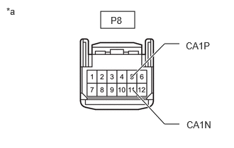
| *a | Front view of wire harness connector
(to Forward Recognition Camera) |
Disconnect the forward recognition camera connector.
Measure the resistance according to the value(s) in the table below.
- Standard Resistance:
Terminal No. (Symbol) Terminal Description Condition Specified Condition P8-5 (CA1P) - P8-11 (CA1N) HIGH-level CAN bus line - LOW-level CAN bus line Cable disconnected from negative (-) auxiliary battery terminal 54 to 69 Ω P8-5 (CA1P) - Body ground HIGH-level CAN bus line - Body ground Cable disconnected from negative (-) auxiliary battery terminal 200 Ω or higher P8-11 (CA1N) - Body ground LOW-level CAN bus line - Body ground Cable disconnected from negative (-) auxiliary battery terminal 200 Ω or higher P8-5 (CA1P) - Positive (+) auxiliary battery terminal HIGH-level CAN bus line - Auxiliary battery positive (+) Cable disconnected from negative (-) auxiliary battery terminal 6 kΩ or higher P8-11 (CA1N) - Positive (+) auxiliary battery terminal LOW-level CAN bus line - Auxiliary battery positive (+) Cable disconnected from negative (-) auxiliary battery terminal 6 kΩ or higher
MILLIMETER WAVE RADAR SENSOR ASSEMBLY
Refer to Terminals of ECU.
Disconnect the cable from the negative (-) auxiliary battery terminal.
Disconnect the millimeter wave radar sensor assembly connector.
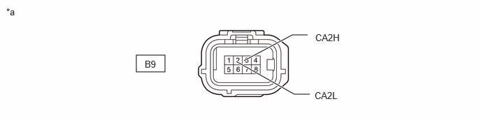
| *a | Front view of wire harness connector
(to Millimeter Wave Radar Sensor Assembly) |
- | - |
Measure the resistance according to the value(s) in the table below.
- Standard Resistance:
Terminal No. (Symbol) Terminal Description Condition Specified Condition B9-3 (CA2H) - B9-2 (CA2L) HIGH-level CAN bus line - LOW-level CAN bus line Cable disconnected from negative (-) auxiliary battery terminal 54 to 69 Ω B9-3 (CA2H) - Body ground HIGH-level CAN bus line - Body ground Cable disconnected from negative (-) auxiliary battery terminal 200 Ω or higher B9-2 (CA2L) - Body ground LOW-level CAN bus line - Body ground Cable disconnected from negative (-) auxiliary battery terminal 200 Ω or higher B9-3 (CA2H) - Positive (+) auxiliary battery terminal HIGH-level CAN bus line - Auxiliary battery positive (+) Cable disconnected from negative (-) auxiliary battery terminal 6 kΩ or higher B9-2 (CA2L) - Positive (+) auxiliary battery terminal LOW-level CAN bus line - Auxiliary battery positive (+) Cable disconnected from negative (-) auxiliary battery terminal 6 kΩ or higher
AIRBAG ECU ASSEMBLY
Refer to Terminals of ECU.
Disconnect the cable from the negative (-) auxiliary battery terminal.
Disconnect the airbag ECU assembly connector.
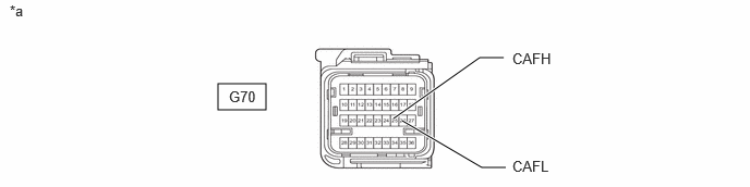
| *a | Front view of wire harness connector
(to Airbag ECU Assembly) |
- | - |
Measure the resistance according to the value(s) in the table below.
- Standard Resistance:
Terminal No. (Symbol) Terminal Description Condition Specified Condition G70-26 (CAFH) - G70-27 (CAFL) HIGH-level CAN bus line - LOW-level CAN bus line Cable disconnected from negative (-) auxiliary battery terminal 54 to 69 Ω G70-26 (CAFH) - Body ground HIGH-level CAN bus line - Body ground Cable disconnected from negative (-) auxiliary battery terminal 200 Ω or higher G70-27 (CAFL) - Body ground LOW-level CAN bus line - Body ground Cable disconnected from negative (-) auxiliary battery terminal 200 Ω or higher G70-26 (CAFH) - Positive (+) auxiliary battery terminal HIGH-level CAN bus line - Auxiliary battery positive (+) Cable disconnected from negative (-) auxiliary battery terminal 6 kΩ or higher G70-27 (CAFL) - Positive (+) auxiliary battery terminal LOW-level CAN bus line - Auxiliary battery positive (+) Cable disconnected from negative (-) auxiliary battery terminal 6 kΩ or higher
COMBINATION METER ASSEMBLY
Refer to Terminals of ECU.
Disconnect the cable from the negative (-) auxiliary battery terminal.
Disconnect the combination meter assembly connector.
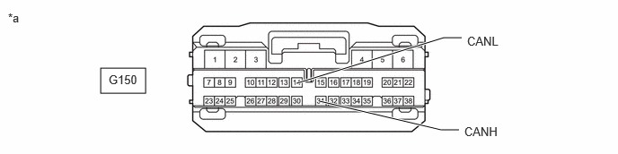
| *a | Front view of wire harness connector
(to Combination Meter Assembly) |
- | - |
Measure the resistance according to the value(s) in the table below.
- Standard Resistance:
Terminal No. (Symbol) Terminal Description Condition Specified Condition G150-31 (CANH) - G150-14 (CANL) HIGH-level CAN bus line - LOW-level CAN bus line Cable disconnected from negative (-) auxiliary battery terminal 108 to 132 Ω G150-31 (CANH) - Body ground HIGH-level CAN bus line - Body ground Cable disconnected from negative (-) auxiliary battery terminal 200 Ω or higher G150-14 (CANL) - Body ground LOW-level CAN bus line - Body ground Cable disconnected from negative (-) auxiliary battery terminal 200 Ω or higher G150-31 (CANH) - Positive (+) auxiliary battery terminal HIGH-level CAN bus line - Auxiliary battery positive (+) Cable disconnected from negative (-) auxiliary battery terminal 6 kΩ or higher G150-14 (CANL) - Positive (+) auxiliary battery terminal LOW-level CAN bus line - Auxiliary battery positive (+) Cable disconnected from negative (-) auxiliary battery terminal 6 kΩ or higher
MAIN BODY ECU (MULTIPLEX NETWORK BODY ECU)
Refer to Terminals of ECU.
Disconnect the cable from the negative (-) auxiliary battery terminal.
Disconnect the main body ECU (multiplex network body ECU) connector.
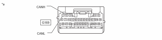
| *a | Front view of wire harness connector
(to Main Body ECU (Multiplex Network Body ECU)) |
- | - |
Measure the resistance according to the value(s) in the table below.
- Standard Resistance:
Terminal No. (Symbol) Terminal Description Condition Specified Condition G169-2 (CANH) - G169-1 (CANL) HIGH-level CAN bus line - LOW-level CAN bus line Cable disconnected from negative (-) auxiliary battery terminal 108 to 132 Ω G169-2 (CANH) - Body ground HIGH-level CAN bus line - Body ground Cable disconnected from negative (-) auxiliary battery terminal 200 Ω or higher G169-1 (CANL) - Body ground LOW-level CAN bus line - Body ground Cable disconnected from negative (-) auxiliary battery terminal 200 Ω or higher G169-2 (CANH) - Positive (+) auxiliary battery terminal HIGH-level CAN bus line - Auxiliary battery positive (+) Cable disconnected from negative (-) auxiliary battery terminal 6 kΩ or higher G169-1 (CANL) - Positive (+) auxiliary battery terminal LOW-level CAN bus line - Auxiliary battery positive (+) Cable disconnected from negative (-) auxiliary battery terminal 6 kΩ or higher
RADIO AND DISPLAY RECEIVER ASSEMBLY (w/o Navigation System)
Refer to Terminals of ECU.
Disconnect the cable from the negative (-) auxiliary battery terminal.
Disconnect the radio and display receiver assembly connector.
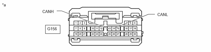
| *a | Front view of wire harness connector
(to Radio and Display Receiver Assembly) |
- | - |
Measure the resistance according to the value(s) in the table below.
- Standard Resistance:
Terminal No. (Symbol) Terminal Description Condition Specified Condition G156-13 (CANH) - G156-14 (CANL) HIGH-level CAN bus line - LOW-level CAN bus line Cable disconnected from negative (-) auxiliary battery terminal 54 to 69 Ω G156-13 (CANH) - Body ground HIGH-level CAN bus line - Body ground Cable disconnected from negative (-) auxiliary battery terminal 200 Ω or higher G156-14 (CANL) - Body ground LOW-level CAN bus line - Body ground Cable disconnected from negative (-) auxiliary battery terminal 200 Ω or higher G156-13 (CANH) - Positive (+) auxiliary battery terminal HIGH-level CAN bus line - Auxiliary battery positive (+) Cable disconnected from negative (-) auxiliary battery terminal 6 kΩ or higher G156-14 (CANL) - Positive (+) auxiliary battery terminal LOW-level CAN bus line - Auxiliary battery positive (+) Cable disconnected from negative (-) auxiliary battery terminal 6 kΩ or higher
NAVIGATION RECEIVER ASSEMBLY (w/ Navigation System)
Refer to Terminals of ECU.
Disconnect the cable from the negative (-) auxiliary battery terminal.
Disconnect the navigation receiver assembly connector.
| *a | Front view of wire harness connector
(to Navigation Receiver Assembly) |
- | - |
Measure the resistance according to the value(s) in the table below.
- Standard Resistance:
Terminal No. (Symbol) Terminal Description Condition Specified Condition G156-13 (CANH) - G156-14 (CANL) HIGH-level CAN bus line - LOW-level CAN bus line Cable disconnected from negative (-) auxiliary battery terminal 54 to 69 Ω G156-13 (CANH) - Body ground HIGH-level CAN bus line - Body ground Cable disconnected from negative (-) auxiliary battery terminal 200 Ω or higher G156-14 (CANL) - Body ground LOW-level CAN bus line - Body ground Cable disconnected from negative (-) auxiliary battery terminal 200 Ω or higher G156-13 (CANH) - Positive (+) auxiliary battery terminal HIGH-level CAN bus line - Auxiliary battery positive (+) Cable disconnected from negative (-) auxiliary battery terminal 6 kΩ or higher G156-14 (CANL) - Positive (+) auxiliary battery terminal LOW-level CAN bus line - Auxiliary battery positive (+) Cable disconnected from negative (-) auxiliary battery terminal 6 kΩ or higher
TELEPHONE TRANSCEIVER
Refer to Terminals of ECU.
Disconnect the cable from the negative (-) auxiliary battery terminal.
Disconnect the telephone transceiver connector.
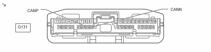
| *a | Front view of wire harness connector
(to Telephone Transceiver) |
- | - |
Measure the resistance according to the value(s) in the table below.
- Standard Resistance:
Terminal No. (Symbol) Terminal Description Condition Specified Condition G131-25 (CANP) - G131-26 (CANN) HIGH-level CAN bus line - LOW-level CAN bus line Cable disconnected from negative (-) auxiliary battery terminal 54 to 69 Ω G131-25 (CANP) - Body ground HIGH-level CAN bus line - Body ground Cable disconnected from negative (-) auxiliary battery terminal 200 Ω or higher G131-26 (CANN) - Body ground LOW-level CAN bus line - Body ground Cable disconnected from negative (-) auxiliary battery terminal 200 Ω or higher G131-25 (CANP) - Positive (+) auxiliary battery terminal HIGH-level CAN bus line - Auxiliary battery positive (+) Cable disconnected from negative (-) auxiliary battery terminal 6 kΩ or higher G131-26 (CANN) - Positive (+) auxiliary battery terminal LOW-level CAN bus line - Auxiliary battery positive (+) Cable disconnected from negative (-) auxiliary battery terminal 6 kΩ or higher
AIR CONDITIONING AMPLIFIER ASSEMBLY
Refer to Terminals of ECU.
Disconnect the cable from the negative (-) auxiliary battery terminal.
Disconnect the air conditioning amplifier assembly connector.
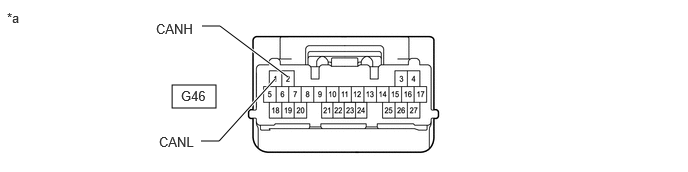
| *a | Front view of wire harness connector
(to Air Conditioning Amplifier Assembly) |
- | - |
Measure the resistance according to the value(s) in the table below.
- Standard Resistance:
Terminal No. (Symbol) Terminal Description Condition Specified Condition G46-2 (CANH) - G46-1 (CANL) HIGH-level CAN bus line - LOW-level CAN bus line Cable disconnected from negative (-) auxiliary battery terminal 54 to 69 Ω G46-2 (CANH) - Body ground HIGH-level CAN bus line - Body ground Cable disconnected from negative (-) auxiliary battery terminal 200 Ω or higher G46-1 (CANL) - Body ground LOW-level CAN bus line - Body ground Cable disconnected from negative (-) auxiliary battery terminal 200 Ω or higher G46-2 (CANH) - Positive (+) auxiliary battery terminal HIGH-level CAN bus line - Auxiliary battery positive (+) Cable disconnected from negative (-) auxiliary battery terminal 6 kΩ or higher G46-1 (CANL) - Positive (+) auxiliary battery terminal LOW-level CAN bus line - Auxiliary battery positive (+) Cable disconnected from negative (-) auxiliary battery terminal 6 kΩ or higher
CLEARANCE WARNING ECU ASSEMBLY
Refer to Terminals of ECU.
Disconnect the cable from the negative (-) auxiliary battery terminal.
Disconnect the clearance warning ECU assembly connector.
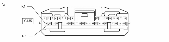
| *a | Front view of wire harness connector
(to Clearance Warning ECU Assembly) |
- | - |
Measure the resistance according to the value(s) in the table below.
- Standard Resistance:
Terminal No. (Symbol) Terminal Description Condition Specified Condition G135-19 (R1) - G135-20 (R2) HIGH-level CAN bus line - LOW-level CAN bus line Cable disconnected from negative (-) auxiliary battery terminal 54 to 69 Ω G135-19 (R1) - Body ground HIGH-level CAN bus line - Body ground Cable disconnected from negative (-) auxiliary battery terminal 200 Ω or higher G135-20 (R2) - Body ground LOW-level CAN bus line - Body ground Cable disconnected from negative (-) auxiliary battery terminal 200 Ω or higher G135-19 (R1) - Positive (+) auxiliary battery terminal HIGH-level CAN bus line - Auxiliary battery positive (+) Cable disconnected from negative (-) auxiliary battery terminal 6 kΩ or higher G135-20 (R2) - Positive (+) auxiliary battery terminal LOW-level CAN bus line - Auxiliary battery positive (+) Cable disconnected from negative (-) auxiliary battery terminal 6 kΩ or higher
CERTIFICATION ECU (SMART KEY ECU ASSEMBLY)
Refer to Terminals of ECU.
Disconnect the cable from the negative (-) auxiliary battery terminal.
Disconnect the certification ECU (smart key ECU assembly) connector.
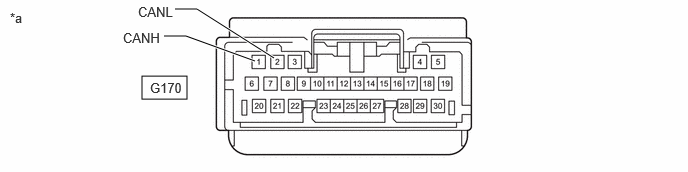
| *a | Front view of wire harness connector
(to Certification ECU (Smart Key ECU Assembly)) |
- | - |
Measure the resistance according to the value(s) in the table below.
- Standard Resistance:
Terminal No. (Symbol) Terminal Description Condition Specified Condition G170-1 (CANH) - G170-2 (CANL) HIGH-level CAN bus line - LOW-level CAN bus line Cable disconnected from negative (-) auxiliary battery terminal 54 to 69 Ω G170-1 (CANH) - Body ground HIGH-level CAN bus line - Body ground Cable disconnected from negative (-) auxiliary battery terminal 200 Ω or higher G170-2 (CANL) - Body ground LOW-level CAN bus line - Body ground Cable disconnected from negative (-) auxiliary battery terminal 200 Ω or higher G170-1 (CANH) - Positive (+) auxiliary battery terminal HIGH-level CAN bus line - Auxiliary battery positive (+) Cable disconnected from negative (-) auxiliary battery terminal 6 kΩ or higher G170-2 (CANL) - Positive (+) auxiliary battery terminal LOW-level CAN bus line - Auxiliary battery positive (+) Cable disconnected from negative (-) auxiliary battery terminal 6 kΩ or higher
MULTIPLEX NETWORK DOOR ECU (w/ Power Back Door System)
Refer to Terminals of ECU.
Disconnect the cable from the negative (-) auxiliary battery terminal.
Disconnect the multiplex network door ECU connector.
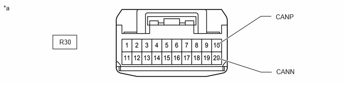
| *a | Front view of wire harness connector
(to Multiplex Network Door ECU) |
- | - |
Measure the resistance according to the value(s) in the table below.
- Standard Resistance:
Terminal No. (Symbol) Terminal Description Condition Specified Condition R30-10 (CANP) - R30-20 (CANN) HIGH-level CAN bus line - LOW-level CAN bus line Cable disconnected from negative (-) auxiliary battery terminal 54 to 69 Ω R30-10 (CANP) - Body ground HIGH-level CAN bus line - Body ground Cable disconnected from negative (-) auxiliary battery terminal 200 Ω or higher R30-20 (CANN) - Body ground LOW-level CAN bus line - Body ground Cable disconnected from negative (-) auxiliary battery terminal 200 Ω or higher R30-10 (CANP) - Positive (+) auxiliary battery terminal HIGH-level CAN bus line - Auxiliary battery positive (+) Cable disconnected from negative (-) auxiliary battery terminal 6 kΩ or higher R30-20 (CANN) - Positive (+) auxiliary battery terminal LOW-level CAN bus line - Auxiliary battery positive (+) Cable disconnected from negative (-) auxiliary battery terminal 6 kΩ or higher
PARKING ASSIST ECU (w/ Panoramic View Monitor System)
Refer to Terminals of ECU.
Disconnect the cable from the negative (-) auxiliary battery terminal.
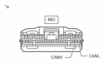
| *a | Front view of wire harness connector
(to Parking Assist ECU) |
Disconnect the parking assist ECU connector.
Measure the resistance according to the value(s) in the table below.
- Standard Resistance:
Terminal No. (Symbol) Terminal Description Condition Specified Condition N62-39 (CANH) - N62-40 (CANL) HIGH-level CAN bus line - LOW-level CAN bus line Cable disconnected from negative (-) auxiliary battery terminal 54 to 69 Ω N62-39 (CANH) - Body ground HIGH-level CAN bus line - Body ground Cable disconnected from negative (-) auxiliary battery terminal 200 Ω or higher N62-40 (CANL) - Body ground LOW-level CAN bus line - Body ground Cable disconnected from negative (-) auxiliary battery terminal 200 Ω or higher N62-39 (CANH) - Positive (+) auxiliary battery terminal HIGH-level CAN bus line - Auxiliary battery positive (+) Cable disconnected from negative (-) auxiliary battery terminal 6 kΩ or higher N62-40 (CANL) - Positive (+) auxiliary battery terminal LOW-level CAN bus line - Auxiliary battery positive (+) Cable disconnected from negative (-) auxiliary battery terminal 6 kΩ or higher
VEHICLE APPROACHING SPEAKER CONTROLLER
Refer to Terminals of ECU.
Disconnect the cable from the negative (-) auxiliary battery terminal.
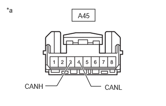
| *a | Front view of wire harness connector
(to Vehicle Approaching Speaker Controller) |
Disconnect the vehicle approaching speaker controller connector.
Measure the resistance according to the value(s) in the table below.
- Standard Resistance:
Terminal No. (Symbol) Terminal Description Condition Specified Condition A45-3 (CANH) - A45-4 (CANL) HIGH-level CAN bus line - LOW-level CAN bus line Cable disconnected from negative (-) auxiliary battery terminal 54 to 69 Ω A45-3 (CANH) - Body ground HIGH-level CAN bus line - Body ground Cable disconnected from negative (-) auxiliary battery terminal 200 Ω or higher A45-4 (CANL) - Body ground LOW-level CAN bus line - Body ground Cable disconnected from negative (-) auxiliary battery terminal 200 Ω or higher A45-3 (CANH) - Positive (+) auxiliary battery terminal HIGH-level CAN bus line - Auxiliary battery positive (+) Cable disconnected from negative (-) auxiliary battery terminal 6 kΩ or higher A45-4 (CANL) - Positive (+) auxiliary battery terminal LOW-level CAN bus line - Auxiliary battery positive (+) Cable disconnected from negative (-) auxiliary battery terminal 6 kΩ or higher
BLIND SPOT MONITOR SENSOR LH (w/ Blind Spot Monitor System)
Refer to Terminals of ECU.
Disconnect the cable from the negative (-) auxiliary battery terminal.
Disconnect the blind spot monitor sensor LH connector.
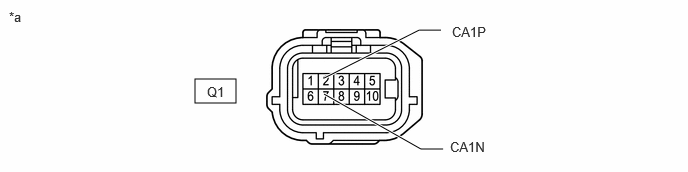
| *a | Front view of wire harness connector
(to Blind Spot Monitor Sensor LH) |
- | - |
Measure the resistance according to the value(s) in the table below.
- Standard Resistance:
Terminal No. (Symbol) Terminal Description Condition Specified Condition Q1-2 (CA1P) - Q1-7 (CA1N) HIGH-level CAN bus line - LOW-level CAN bus line Cable disconnected from negative (-) auxiliary battery terminal 54 to 69 Ω Q1-2 (CA1P) - Body ground HIGH-level CAN bus line - Body ground Cable disconnected from negative (-) auxiliary battery terminal 200 Ω or higher Q1-7 (CA1N) - Body ground LOW-level CAN bus line - Body ground Cable disconnected from negative (-) auxiliary battery terminal 200 Ω or higher Q1-2 (CA1P) - Positive (+) auxiliary battery terminal HIGH-level CAN bus line - Auxiliary battery positive (+) Cable disconnected from negative (-) auxiliary battery terminal 6 kΩ or higher Q1-7 (CA1N) - Positive (+) auxiliary battery terminal LOW-level CAN bus line - Auxiliary battery positive (+) Cable disconnected from negative (-) auxiliary battery terminal 6 kΩ or higher
METER MIRROR SUB-ASSEMBLY (w/ Headup Display System)
Refer to Terminals of ECU.
Disconnect the cable from the negative (-) auxiliary battery terminal.
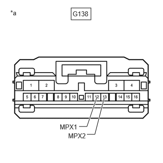
| *a | Front view of wire harness connector
(to Meter Mirror Sub-assembly) |
Disconnect the meter mirror sub-assembly connector.
Measure the resistance according to the value(s) in the table below.
- Standard Resistance:
Terminal No. (Symbol) Terminal Description Condition Specified Condition G138-12 (MPX1) - G138-13 (MPX2) HIGH-level CAN bus line - LOW-level CAN bus line Cable disconnected from negative (-) auxiliary battery terminal 54 to 69 Ω G138-12 (MPX1) - Body ground HIGH-level CAN bus line - Body ground Cable disconnected from negative (-) auxiliary battery terminal 200 Ω or higher G138-13 (MPX2) - Body ground LOW-level CAN bus line - Body ground Cable disconnected from negative (-) auxiliary battery terminal 200 Ω or higher G138-12 (MPX1) - Positive (+) auxiliary battery terminal HIGH-level CAN bus line - Auxiliary battery positive (+) Cable disconnected from negative (-) auxiliary battery terminal 6 kΩ or higher G138-13 (MPX2) - Positive (+) auxiliary battery terminal LOW-level CAN bus line - Auxiliary battery positive (+) Cable disconnected from negative (-) auxiliary battery terminal 6 kΩ or higher
TIRE PRESSURE WARNING ECU AND RECEIVER
Refer to Terminals of ECU.
Disconnect the cable from the negative (-) auxiliary battery terminal.
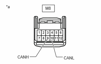
| *a | Front view of wire harness connector
(to Tire Pressure Warning ECU and Receiver) |
Disconnect the tire pressure warning ECU and receiver connector.
Measure the resistance according to the value(s) in the table below.
- Standard Resistance:
Terminal No. (Symbol) Terminal Description Condition Specified Condition M8-9 (CANH) - M8-10 (CANL) HIGH-level CAN bus line - LOW-level CAN bus line Cable disconnected from negative (-) auxiliary battery terminal 54 to 69 Ω M8-9 (CANH) - Body ground HIGH-level CAN bus line - Body ground Cable disconnected from negative (-) auxiliary battery terminal 200 Ω or higher M8-10 (CANL) - Body ground LOW-level CAN bus line - Body ground Cable disconnected from negative (-) auxiliary battery terminal 200 Ω or higher M8-9 (CANH) - Positive (+) auxiliary battery terminal HIGH-level CAN bus line - Auxiliary battery positive (+) Cable disconnected from negative (-) auxiliary battery terminal 6 kΩ or higher M8-10 (CANL) - Positive (+) auxiliary battery terminal LOW-level CAN bus line - Auxiliary battery positive (+) Cable disconnected from negative (-) auxiliary battery terminal 6 kΩ or higher
BATTERY ECU ASSEMBLY
Refer to Terminals of ECU.
Disconnect the cable from the negative (-) auxiliary battery terminal.
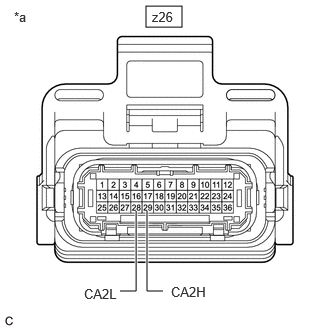
| *a | Front view of wire harness connector
(to Battery ECU Assembly) |
Disconnect the battery ECU assembly connector.
Measure the resistance according to the value(s) in the table below.
- Standard Resistance:
Terminal No. (Symbol) Terminal Description Condition Specified Condition z26-29 (CA2H) - z26-28 (CA2L) HIGH-level CAN bus line - LOW-level CAN bus line Cable disconnected from negative (-) auxiliary battery terminal 54 to 69 Ω z26-29 (CA2H) - Body ground HIGH-level CAN bus line - Body ground Cable disconnected from negative (-) auxiliary battery terminal 200 Ω or higher z26-28 (CA2L) - Body ground LOW-level CAN bus line - Body ground Cable disconnected from negative (-) auxiliary battery terminal 200 Ω or higher z26-29 (CA2H) - Positive (+) auxiliary battery terminal HIGH-level CAN bus line - Auxiliary battery positive (+) Cable disconnected from negative (-) auxiliary battery terminal 6 kΩ or higher z26-28 (CA2L) - Positive (+) auxiliary battery terminal LOW-level CAN bus line - Auxiliary battery positive (+) Cable disconnected from negative (-) auxiliary battery terminal 6 kΩ or higher
BUS BUFFER ECU (w/ CAN Compatible Optional Devices)
Disconnect the cable from the negative (-) auxiliary battery terminal.
Disconnect the bus buffer ECU connector.
- HINT:
-
Disconnect any CAN compatible optional devices from the option connector.
Measure the resistance according to the value(s) in the table below.
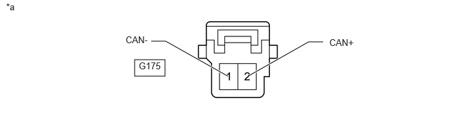
| *a | Front view of wire harness connector
(to Bus Buffer ECU) |
- | - |
- Standard Resistance:
Terminal No. (Symbol) Terminal Description Condition Specified Condition G175-2 (CAN+) - G175-1 (CAN-) HIGH-level CAN bus line - LOW-level CAN bus line Cable disconnected from negative (-) auxiliary battery terminal 54 to 69 Ω G175-2 (CAN+) - Body ground HIGH-level CAN bus line - Body ground Cable disconnected from negative (-) auxiliary battery terminal 200 Ω or higher G175-1 (CAN-) - Body ground LOW-level CAN bus line - Body ground Cable disconnected from negative (-) auxiliary battery terminal 200 Ω or higher G175-2 (CAN+) - Positive (+) auxiliary battery terminal HIGH-level CAN bus line - Positive (+) auxiliary battery terminal Cable disconnected from negative (-) auxiliary battery terminal 6 kΩ or higher G175-1 (CAN-) - Positive (+) auxiliary battery terminal LOW-level CAN bus line - Positive (+) auxiliary battery terminal Cable disconnected from negative (-) auxiliary battery terminal 6 kΩ or higher