PARK ASSIST / MONITORING TOYOTA PARKING ASSIST-SENSOR SYSTEM TERMINALS OF ECU
CLEARANCE WARNING ECU ASSEMBLY

Disconnect the G135 clearance warning ECU assembly connector.
Measure the voltage and resistance on the wire harness side connector according to the value(s) in the table below.
| Terminal No. (Symbol) | Terminal Description | Condition | Specified Condition |
|---|---|---|---|
| G135-18 (IG) - G135-38 (E) | IG power source signal | Ignition switch off | Below 1 V |
| Ignition switch ON | 11 to 14 V | ||
| G135-38 (E) - Body ground | Ground | Always | Below 1 Ω |
Reconnect the G135 clearance warning ECU assembly connector.
Measure the voltage and resistance and check for pulses according to the value(s) in the table below.
| Terminal No. (Symbol) | Terminal Description | Condition | Specified Condition |
|---|---|---|---|
| G135-14 (BOF) - G135-38 (E) | Power source for front sensor circuit | Ignition switch off | Below 1 V |
·
Ignition switch ON ·
TOYOTA parking assist-sensor system on |
Approximately 9 V | ||
| G135-15 (E5) - G135-38 (E) | Ground for front clearance sonar | Always | Below 1 Ω |
| G135-37 (SOF) - G135-15 (E5) | Front sensor communication signal (Front clearance sonar sensor) | ·
Ignition switch ON ·
TOYOTA parking assist-sensor system on ·
Shift lever in any position other than P ·
Vehicle speed less than approximately 10 km/h (6 mph) |
Pulse generation
(Refer to waveform 1) |
| G135-17 (CBZ) - G135-30 (EF) | No. 1 clearance warning buzzer signal | Buzzer sounding | Pulse generation
(Refer to waveform 2) |
| G135-35 (BOR) - G135-38 (E) | Power source for rear sensor circuit | Ignition switch off | Below 1 V |
·
Ignition switch ON ·
TOYOTA parking assist-sensor system on |
Approximately 9 V | ||
| G135-34 (E1) - G135-38 (E) | Ground for rear clearance sonar | Always | Below 1 Ω |
| G135-11 (SOR) - G135-34 (E1) | Rear sensor communication signal (Rear clearance sonar sensor) | ·
Ignition switch ON ·
TOYOTA parking assist-sensor system on ·
Shift lever in R |
Pulse generation
(Refer to waveform 1) |
| G135-19 (R1) | CAN communication signal | - | - |
| G135-20 (R2) | CAN communication signal | - | - |
Using an oscilloscope, check waveform 1.
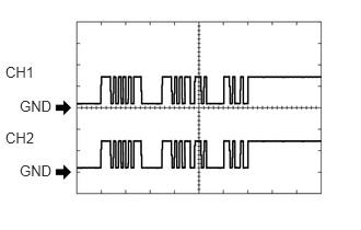
Waveform 1 (Reference)
| Item | Content |
|---|---|
| Measurement terminal | ·
CH1: G135-37 (SOF) - G135-15 (E5) ·
CH2: G135-11 (SOR) - G135-34 (E1) |
| Measurement setting | 5 V/DIV., 1 ms./DIV. |
| Condition | ·
Ignition switch ON ·
TOYOTA parking assist-sensor system on ·
Shift lever in any position other than P (CH1) ·
Shift lever in R (CH2) ·
Vehicle speed less than approximately 10 km/h (6 mph) (CH1) |
Using an oscilloscope, check waveform 2.
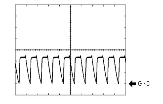
Waveform 2 (Reference)
| Item | Content |
|---|---|
| Measurement terminal | G135-17 (CBZ) - G135-30 (EF) |
| Measurement setting | 2 V/DIV., 500 μs./DIV. |
| Condition | Buzzer sounding |
- HINT:
-
The amplitude of the waveform changes according to the set volume.