RM36D0EC
_55
Steering
_083083
POWER ASSIST SYSTEMS
_0403821
POWER STEERING SYSTEM
U
POWER ASSIST SYSTEMS POWER STEERING SYSTEM TERMINALS OF ECU
TERMINALS OF ECU
3.354,0.146 3.802,0.406
0.448,0.26
0.104,0.052 0.417,0.208
0.313,0.156
10
false
*a
3.448,0.198 3.802,0.396
0.354,0.198
10
false
C54
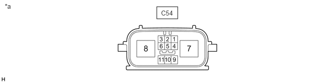
| *a | Component without harness connected
(Rack and Pinion Power Steering Gear Assembly) |
- | - |
- HINT:
- ·
The rack and pinion power steering gear assembly uses waterproof connectors. Therefore, voltage or waveforms cannot be checked with the connectors connected to the vehicle.
·Use the Data List and Active Test on the GTS to check the operation of the rack and pinion power steering gear assembly and check that communication is established.
| Terminal No. (Symbol) | Terminal Description |
|---|---|
| C54-4 (IG) | IG power source |
| C54-7 (PGND) | Power ground |
| C54-8 (PIG) | Power source |
| C54-10 (CANH) | CAN communication line |
| C54-11 (CANL) | CAN communication line |
CHECK WIRE HARNESS SIDE CONNECTOR
1.917,0.771 2.333,1
0.417,0.229
2,0.802 2.458,1
0.458,0.198
10
false
C54
0.094,0.052 0.406,0.25
0.313,0.198
10
false
*a
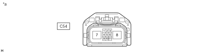
| *a | Front view of wire harness connector
(to Rack and Pinion Power Steering Gear Assembly) |
- | - |
a.
Disconnect the C54 rack and pinion power steering gear assembly connector.
b.
Measure the voltage and resistance according to the value(s) in the table below.
| Terminal No. (Symbol) | Terminal Description | Condition | Specified Condition |
|---|---|---|---|
| C54-4 (IG) - Body ground | IG power source | Ignition switch ON | 8 to 16 V |
| C54-7 (PGND) - Body ground | Power ground | Always | Below 1 Ω |
| C54-8 (PIG) - Body ground | Power source | Always | 9 to 16 V |