☰ Toyota RAV4☰ فهرستVehicle Exterior › ACOUSTIC VEHICLE ALERTING SYSTEM › ACOUSTIC VEHICLE ALERTING SYSTEM
RM36D0EC
_59
Vehicle Exterior
_171816
ACOUSTIC VEHICLE ALERTING SYSTEM
_0711751
ACOUSTIC VEHICLE ALERTING SYSTEM
U
ACOUSTIC VEHICLE ALERTING SYSTEM ACOUSTIC VEHICLE ALERTING SYSTEM TERMINALS OF ECU
CHECK VEHICLE APPROACHING SPEAKER CONTROLLER

3.302,0.094 3.854,0.354
0.552,0.26
3.458,0.146 4.177,0.375
0.719,0.229
10
false
A45
a.
Disconnect the A45 vehicle approaching speaker controller connector.
b.
Measure the voltage and resistance according to the value(s) in the table below.
| Terminal No. (Symbol) | Terminal Description | Condition | Specified Condition |
|---|---|---|---|
| A45-1 (IG) - Body ground | IG power supply | Power switch on (IG) | 11 to 14 V |
| Power switch off | Below 1 V | ||
| A45-6 (GND) - Body ground | Ground | Always | Below 1 Ω |
c.
Connect the A45 vehicle approaching speaker controller connector.
d.
Measure the check for pulses according to the value(s) in the table below.
| Terminal No. (Symbol) | Terminal Description | Condition | Specified Condition |
|---|---|---|---|
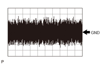
| A45-7 (SP+) - A45-8 (SP-) | Vehicle approaching speaker output | Vehicle approaching speaker operating | A waveform synchronized with the sound is output.
(See Waveform 1) |
| A45-3 (CANH) - A45-6 (GND) | CAN communication line | Power switch on (IG) | Pulse generation |
| A45-4 (CANL) - A45-6 (GND) | CAN communication line | Power switch on (IG) | Pulse generation |
i.
3.125,1.031 3.427,1.208
0.302,0.177
10
false
GND
Waveform 1
| Item | Condition |
|---|---|
| Tester Connection | A45-7 (SP+) - A45-8 (SP-) |
| Tool Setting | 1 V/DIV., 500 ms./DIV. |
| Condition | Vehicle approaching speaker operating |