DOOR / HATCH POWER BACK DOOR SYSTEM TERMINALS OF ECU
CHECK MULTIPLEX NETWORK DOOR ECU
Disconnect the R28, R29, and R30 multiplex network door ECU connectors.
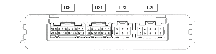
Measure the voltage and resistance according to the value(s) in the table below.
| Terminal No. (Symbol) | Terminal Description | Condition | Specified Condition |
|---|---|---|---|
| R30-9 (IG) - Body ground | IG power supply | Ignition switch ON | 11 to 14 V |
| Ignition switch off | Below 1 V | ||
| R30-7 (ECUB) - Body ground | Auxiliary battery power supply | Ignition switch off | 11 to 14 V |
| R29-5 (B) - Body ground | Auxiliary battery power supply | Ignition switch off | 11 to 14 V |
| R28-4 (GND) - Body ground | Body ground | Always | Below 1 Ω |
Reconnect the R28, R29, and R30 multiplex network door ECU connectors.
Measure the voltage and waveform according to the value(s) in the table below.
| Terminal No. (Symbol) | Terminal Description | Condition | Specified Condition |
|---|---|---|---|
| R28-2 (DC+) - R28-6 (DC-) | Back door lock assembly (back door lock motor) circuit | Back door lock motor operating | 11 to 14 V |
| Back door lock motor not operating | Below 1 V | ||
| R31-1 (OSL) - R31-9 (OSE) | Power back door sensor assembly LH signal | Power back door sensor assembly LH not pressed | 4 to 6 V |
| Power back door sensor assembly LH pressed | Below 1 V | ||
| R31-3 (DSV2) - Body ground | Power back door unit assembly RH (door sensor) power supply | Always | 7 V or higher |
| R31-4 (DSV) - Body ground | Power back door unit assembly LH (door sensor) power supply | Always | 7 V or higher |
| R31-5 (DS2) - Body ground | Power back door unit assembly LH (door sensor) signal | Power back door not operating | 7 V or higher |
| Power back door operating | Pulse generation
(See waveform 2) |
||
| R31-6 (DS12) - Body ground | Power back door unit assembly RH (door sensor) signal | Power back door not operating | 7 V or higher |
| Power back door operating | Pulse generation
(See waveform 1) |
||
| R31-8 (OSR) - R30-9 (OSE) | Power back door sensor assembly RH signal | Power back door sensor assembly RH not pressed | 4 to 6 V |
| Power back door sensor assembly RH pressed | Below 1 V | ||
| R31-10 (DSG2) - Body ground | Power back door unit assembly RH (door sensor) ground | Always | Below 1 V |
| R31-11 (DSG) - Body ground | Power back door unit assembly LH (door sensor) ground | Always | Below 1 V |
| R31-12 (DS22) - Body ground | Power back door unit assembly RH (door sensor) signal | Power back door not operating | 7 V or higher |
| Power back door operating | Pulse generation
(See waveform 2) |
||
| R31-13 (DS1) - Body ground | Power back door unit assembly LH (door sensor) signal | Power back door not operating | 7 V or higher |
| Power back door operating | Pulse generation
(See waveform 1) |
||
| R30-1 (BZR+) - Body ground | Power back door warning buzzer signal | Power back door warning buzzer sounding | Pulse generation |
| Power back door warning buzzer not sounding | Below 1 V | ||
| R30-3 (FUL) - Body ground | Back door lock with courtesy light switch assembly input | Back door open | Below 1 V |
| Back door closed | Pulse generation | ||
| R30-5(HAF) - Body ground | Back door lock with courtesy light switch assembly lock signal | Back door closed | 11 to 14 V |
| Back door fully open | Below 1 V | ||
| R30-11(LIB) - Body ground | Back door lock with courtesy light switch assembly lock signal | Back door is locked | 11 to 14 V |
| Back door is unlocked | Below 1 V | ||
| R30-12 (KSIN) - Body ground | Kick detection signal | Ignition switch ON, kick door control sensor not detecting a foot → detecting a foot | Pulse generation
(See waveform 3) |
| R30-13(PAWL) - Body ground | Back door lock with courtesy light switch assembly lock signal | Back door fully open | Below 1 V |
| Back door ajar | 11 to 14 V | ||
| Back door closed | 11 to 14 V | ||
| Operation complete | Below 1 V | ||
| R30-14 (BDDN) - Body ground | Power back door control switch signal | Power back door control switch on | Below 1 V |
| Power back door control switch off | Pulse generation | ||
| R30-15(POS) - Body ground | Back door lock with courtesy light switch assembly signal | Back door open | Below 1 V |
| Back door closer operating | 11 to 14 V | ||
| Operation complete | Below 1 V |
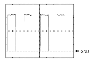
Using an oscilloscope, check waveform 1.
| Item | Condition |
|---|---|
| Tester Connection | ·
R31-13 (DS1) - Body ground ·
R31-6 (DS12) - Body ground |
| Tool Setting | 2 V/DIV., 2 ms./DIV. |
| Vehicle Condition | Power back door operating |
- HINT:
- ·
The period changes in accordance to the speed at which the power back door is opened and closed.
·The wave height changes in accordance with the auxiliary battery voltage.
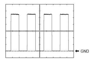
Using an oscilloscope, check waveform 2.
| Item | Condition |
|---|---|
| Tester Connection | ·
R31-5 (DS2) - Body ground ·
R31-12 (DS22) - Body ground |
| Tool Setting | 2 V/DIV., 2 ms./DIV. |
| Vehicle Condition | Power back door operating |
- HINT:
- ·
The period changes in accordance to the speed at which the power back door is opened and closed.
·The wave height changes in accordance with the auxiliary battery voltage.
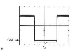
| *a | Kick detection signal |
Using an oscilloscope, check waveform 3.
| Item | Content |
|---|---|
| Tester Connection | R30-12 (KSIN) - Body ground |
| Tool Setting | 2 V/DIV., 50 ms./DIV. |
| Vehicle Condition | Ignition switch ON, kick door control sensor not detecting a foot → detecting a foot |
CHECK MAIN BODY ECU (MULTIPLEX NETWORK BODY ECU) AND POWER DISTRIBUTION BOX ASSEMBLY

| *1 | Power Distribution Box Assembly | *2 | Main Body ECU (Multiplex Network Body ECU) |
Remove the main body ECU (multiplex network body ECU) from the power distribution box assembly.
Connect the power distribution box assembly connectors.
Measure the voltage and resistance according to the value(s) in the table below.
| Terminal No. (Symbol) | Terminal Description | Condition | Specified Condition |
|---|---|---|---|
| A-26 (BECU) - Body ground | Auxiliary battery power supply | Ignition switch off | 11 to 14 V |
| A-27 (IGR) - Body ground | IG power supply | Ignition switch ON | 11 to 14 V |
| Ignition switch off | Below 1 V | ||
| A-13 (GND1) - Body ground | Body ground | Always | Below 1 Ω |
| A-14 (GND2) - Body ground | Body ground | Always | Below 1 Ω |
Install the main body ECU (multiplex network body ECU).
Measure the voltage and waveform according to the value(s) in the table below.
| Terminal No. (Symbol) | Terminal Description | Condition | Specified Condition |
|---|---|---|---|
| A-15 (LIN2) - Body ground | LIN communication line | Ignition switch ON | Pulse generation |
| G167-7 (LSBO) - Body ground | Back door lock signal | Back door locked | Below 1 V |
| Back door unlocked | 11 to 14 V | ||
| G168-21 (PBDS) - Body ground | Power back door control switch signal | Power back door control switch off | Pulse generation |
| Power back door control switch on | Below 1 V |
CHECK CERTIFICATION ECU (SMART KEY ECU ASSEMBLY) (for Entry Function, HV Model)
CHECK CERTIFICATION ECU (SMART KEY ECU ASSEMBLY) (for Entry Function, Gasoline Model)