SEAT BELT REAR SEAT OUTER BELT ASSEMBLY(for Wagon) INSTALLATION
CAUTION / NOTICE / HINT
- CAUTION:
- ·
Wear protective gloves. Sharp areas on the parts may injure your hands.
·There is risk of injury.
- HINT:
- ·
Use the same procedure for RHD and LHD vehicles.
·The procedure listed below is for LHD vehicles.
·Use the same procedure for the RH and LH sides.
·The following procedure is for the LH side.
PROCEDURE

 1.INSPECT REAR SEAT OUTER BELT ASSEMBLY
73015A
2.INSTALL OUTER BELT ANCHOR BRACKET SUB-ASSEMBLY RH (for 60/40 Split Seat Type RH Side)
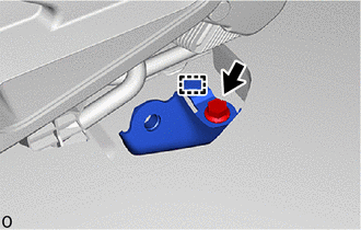
Attach the guide and install the outer belt anchor bracket sub-assembly RH with the bolt.
- Torque:
- 42 N*m (428 kgf*cm, 31 ft.*lbf)
73570A
3.INSTALL NO. 3 SEAT OUTER BELT ASSEMBLY LH
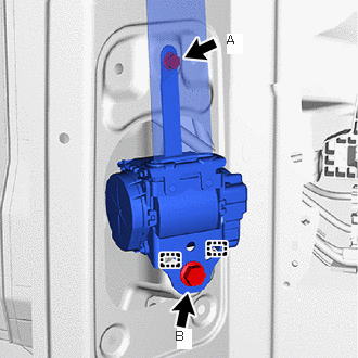
Attach the guide.
Temporarily install the No. 3 seat outer belt assembly LH with the 2 bolts.
Tighten the 2 bolts in the order shown in the illustration.
- Torque:
- Bolt A : 12.5 N*m (127 kgf*cm, 9 ft.*lbf)
- Bolt B : 42 N*m (428 kgf*cm, 31 ft.*lbf)
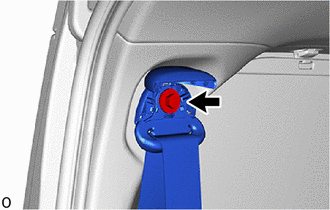
Install the bolt.
- Torque:
- 42 N*m (428 kgf*cm, 31 ft.*lbf)
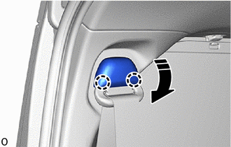

|
Close in this Direction |
Attach the claw and close the cover as shown in the illustration.
62520B
4.INSTALL QUARTER TRIM PANEL ASSEMBLY LH
67872A
5.INSTALL NO. 1 SLIDE DOOR WEATHERSTRIP LH
- HINT:
-
Use the same procedure described for the RH side.
73570A
6.INSTALL NO. 3 SEAT OUTER BELT ASSEMBLY LH
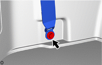
Install the floor anchor of the No. 3 seat outer belt assembly LH with the bolt.
- Torque:
- 42 N*m (428 kgf*cm, 31 ft.*lbf)
Check that the ELR locks.
With the No. 3 seat outer belt assembly LH installed to the vehicle, check that the belt locks when it is pulled out quickly.
73233
7.INSTALL OUTER LAP BELT ANCHOR COVER

| *a | Guide A |
| *b | Guide B |
|
|
Install in this Direction (1) |

|
Install in this Direction (2) |
Attach the guide B in the installation direction (1) shown in the illustration.
Attach the guide A in the installation direction (2) shown in the illustration and install the outer lap belt anchor cover.
67935
8.INSTALL BACK DOOR SCUFF PLATE
9.INSTALL REAR SEAT ASSEMBLY
for 60/40 Split Seat Type 40 Side:
for 60/40 Split Seat Type 60 Side:
for Manual Captain Seat:
for Power Captain Seat:
10.CONNECT CABLE TO NEGATIVE BATTERY TERMINAL (for First Row)
11. INITIALIZATION AFTER RECONNECTING BATTERY TERMINAL (for First Row)
- HINT:
-
When disconnecting and reconnecting the battery, there is an automatic learning function that completes learning when the respective system is used.
12. PERFORM DIAGNOSTIC SYSTEM CHECK (for First Row)
13.CHECK SRS WARNING LIGHT (for First Row)
14.INSPECT SEAT BELT WARNING SYSTEM
15.INSPECT REAR SEAT ASSEMBLY
16.INSPECT SEAT HEATER SYSTEM (w/ Seat Heater System)