DOOR / HATCH FUEL LID LOCK CONTROL CABLE ASSEMBLY(for RHD) INSTALLATION
PROCEDURE

 77378A
1.INSTALL FUEL FILLER OPENING LID LOCK COVER
77378A
1.INSTALL FUEL FILLER OPENING LID LOCK COVER
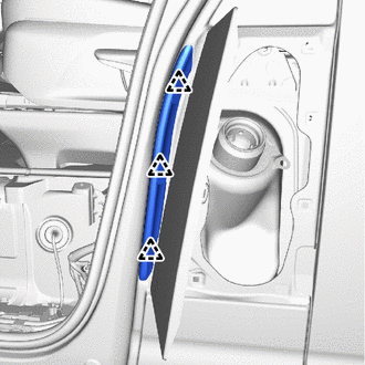
Attach the clip and install the fuel filler opening lid lock cover.
77037
2.INSTALL FUEL FILLER OPENING LID LOCK SUB-ASSEMBLY

Install the fuel filler opening lid lock sub-assembly with the nut.
- Torque:
- 8.5 N*m (87 kgf*cm, 75 in.*lbf)
77035
3.INSTALL FUEL LID LOCK CONTROL CABLE SUB-ASSEMBLY
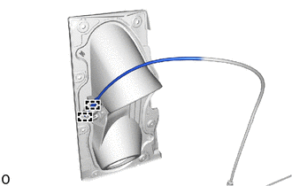
Attach the clamp and install the fuel lid lock control cable sub-assembly to the fuel filler opening lid lock sub-assembly.
77293A
4.INSTALL NO. 3 FUEL TANK FILLER PIPE SHIELD
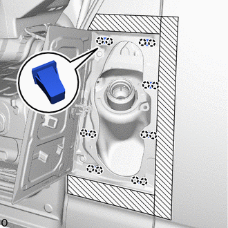
Attach the claw and install the 7 grommets.
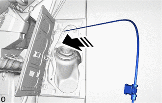

|
Install in this Direction |
Insert the fuel lid lock control cable sub-assembly into the vehicle from the service hole on the vehicle side as shown in the illustration.
While pulling out the fuel tank filler pipe shield assembly, install the No. 3 fuel tank filler pipe shield as shown in the illustration.
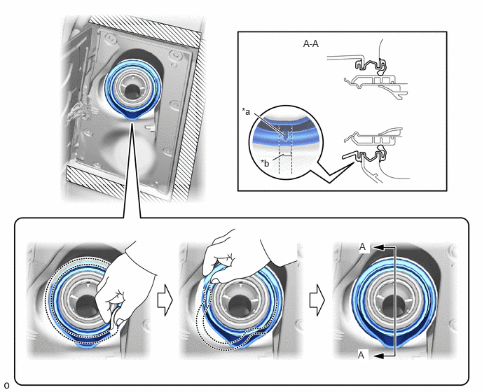
| *a | Protrusion | *b | Rib |
- HINT:
-
Align the protrusion of the fuel tank filler pipe shield assembly with the body rib and install the fuel tank filler pipe shield assembly as shown in the illustration.
w/ Urea SCR System:
- HINT:
-
Use the same procedure to install the fuel tank filler pipe shield assembly.
Install the fuel inlet box ring to the fuel tank filler pipe shield assembly as shown in the illustration.
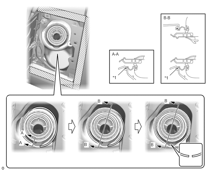
| *1 | Fuel Inlet Box Ring | - | - |
- HINT:
-
Put the cut in the fuel inlet box ring downward.
w/ Urea SCR System:
- HINT:
-
Use the same procedure to install the fuel inlet box ring.
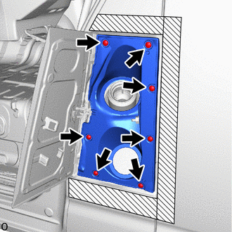
Using a 4 mm hexagon socket wrench, install the No. 3 fuel tank filler pipe shield with the 7 screws.
Remove the protective tape.
77310A
5.INSTALL FUEL TANK CAP ASSEMBLY
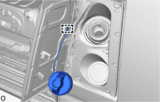
Attach the clamp and install the fuel tank cap assembly.
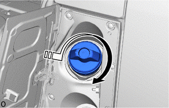
|
|
Install in this Direction |
Install the fuel tank cap assembly as shown in the illustration.
w/ Urea SCR System:
- HINT:
-
Use the same procedure to install the fuel inlet box ring.
77035
6.CONNECT FUEL LID LOCK CONTROL CABLE SUB-ASSEMBLY
Attach the clamp and connect the fuel lid lock control cable sub-assembly.
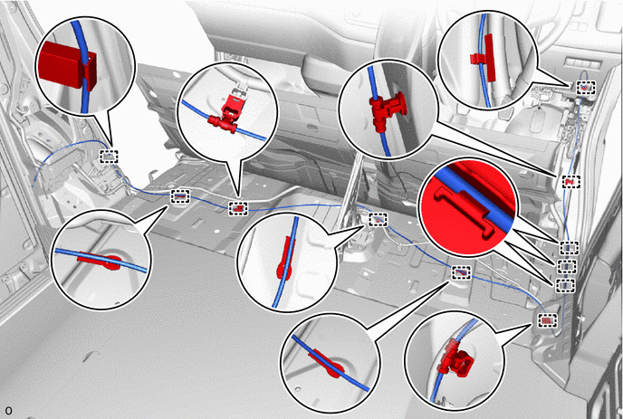
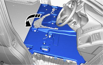
|
|
Install in this Direction |
Install the front floor mat assembly as shown in the illustration.
77306
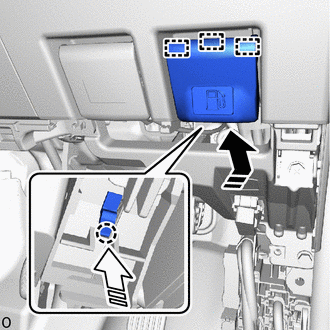
7.INSTALL FUEL LID LOCK OPEN LEVER SUB-ASSEMBLY
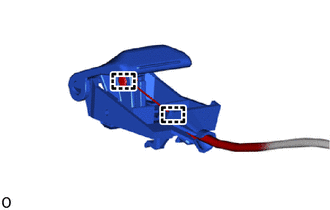
Attach the clamp and install the fuel lid lock open lever sub-assembly to the fuel lid lock control cable sub-assembly.
|
|
Install in this Direction (1) |

|
Install in this Direction (2) |
Attach the claw and guide to install the fuel lid lock open lever sub-assembly in the direction indicated by the arrow as shown in the illustration.
55641
8.INSTALL NO. 1 INSTRUMENT PANEL UNDER COVER
73220
9.INSTALL FRONT SEAT OUTER BELT ASSEMBLY LH
10.INSTALL FRONT CONSOLE BOX (w/ Console Box)
62111C
11.INSTALL COWL SIDE TRIM BOARD RH
67913B
12.INSTALL FRONT DOOR SCUFF PLATE RH
- HINT:
-
Use the same procedure described for the LH side.
67911B
13.INSTALL FRONT DOOR SCUFF PLATE RH
- HINT:
-
Use the same procedure described for the LH side.
14.INSTALL FRONT SEAT ASSEMBLY RH
- HINT:
-
Use the same procedure for the RH and LH sides.
for Separate Seat Type:
for Fixed Bench Seat Type:
for Sliding Bench Seat Type:
15.CONNECT CABLE TO NEGATIVE BATTERY TERMINAL (w/ Front Seat Side Airbag)
16. INITIALIZATION AFTER RECONNECTING BATTERY TERMINAL (w/ Front Seat Side Airbag)
- HINT:
-
When disconnecting and reconnecting the battery, there is an automatic learning function that completes learning when the respective system is used.
17. CHECK SRS WARNING LIGHT (w/ Front Seat Side Airbag)
18. PERFORM DIAGNOSTIC SYSTEM CHECK (w/ Front Seat Side Airbag)
19.INSPECT SEAT BELT WARNING SYSTEM (w/ Seat Belt Warning System)