SEAT BELT FRONT SEAT OUTER BELT ASSEMBLY(for Semi-trim) INSTALLATION
CAUTION / NOTICE / HINT
- HINT:
- ·
Use the same procedure for RHD and LHD vehicles.
·The procedure listed below is for LHD vehicles.
PROCEDURE

 73200A
1.INSTALL FRONT SHOULDER BELT ANCHOR ADJUSTER ASSEMBLY
73200A
1.INSTALL FRONT SHOULDER BELT ANCHOR ADJUSTER ASSEMBLY
- HINT:
-
Use the same procedure for the other side.
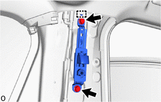
Attach the guide.
Install the front shoulder belt anchor adjuster assembly with the 2 bolts.
- Torque:
- 42 N*m (428 kgf*cm, 31 ft.*lbf)
73024
2.INSTALL FRONT SHOULDER BELT ANCHOR PLATE SUB-ASSEMBLY LH
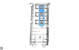
Attach the guide and install the front shoulder belt anchor plate sub-assembly LH.
73023
3.INSTALL FRONT SHOULDER BELT ANCHOR PLATE SUB-ASSEMBLY RH
- HINT:
-
Use the same procedure described for the LH side.
62411
4.INSTALL CENTER PILLAR GARNISH RH
62412
5.INSTALL CENTER PILLAR GARNISH LH
6.INSPECT FRONT SEAT OUTER BELT ASSEMBLY
73220
7.INSTALL FRONT SEAT OUTER BELT ASSEMBLY LH
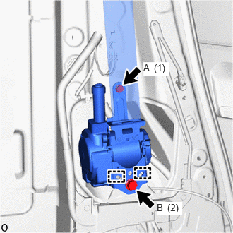
Attach the guide.
Temporarily install the front seat outer belt assembly LH with the 2 bolts.
Tighten the 2 bolts in the order shown in the illustration.
- Torque:
- Bolt A : 12.5 N*m (127 kgf*cm, 9 ft.*lbf)
- Bolt B : 42 N*m (428 kgf*cm, 31 ft.*lbf)
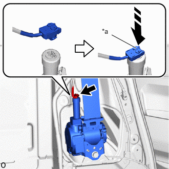
| *a | Locking Button |

|
Lock in this Direction |
w/ Pretensioner and Force Limiter:
Connect the pretensioner connector and lock the locking button as shown in the illustration.
- NOTICE:
- ·
When handling the pretensioner connector, take care not to damage the pretensioner wire harness.
·Securely lock the locking button.
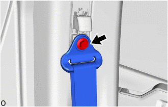
Install the bolt.
- Torque:
- 42 N*m (428 kgf*cm, 31 ft.*lbf)
73210
8.INSTALL FRONT SEAT OUTER BELT ASSEMBLY RH
- HINT:
-
Use the same procedure described for the LH side.
73178C
9.INSTALL SEAT BELT ANCHOR COVER CAP
- HINT:
-
Use the same procedure for the other side.
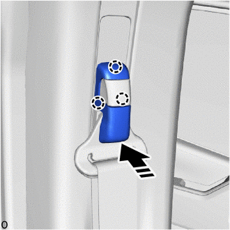
|
|
Install in this Direction |
Attach the claw and install the seat belt anchor cover cap as shown in the illustration.
62413A
10.INSTALL LOWER CENTER PILLAR GARNISH RH
62414A
11.INSTALL LOWER CENTER PILLAR GARNISH LH
- HINT:
-
Use the same procedure described for the RH side.
67871E
12.INSTALL NO. 1 SLIDE DOOR WEATHERSTRIP RH
67872A
13.INSTALL NO. 1 SLIDE DOOR WEATHERSTRIP LH (for 5 Door)
- HINT:
-
Use the same procedure described for the RH side.
62312B
14.INSTALL FRONT DOOR OPENING TRIM WEATHERSTRIP LH
62311B
15.INSTALL FRONT DOOR OPENING TRIM WEATHERSTRIP RH
- HINT:
-
Use the same procedure described for the LH side.
67917C
16.INSTALL REAR DOOR SCUFF PLATE RH
67918D
17.INSTALL REAR DOOR SCUFF PLATE LH (for 5 Door)
- HINT:
-
Use the same procedure described for the RH side.
74707
18.INSTALL NO. 1 HAND GRIP FRAME SUB-ASSEMBLY (w/ Hand Rail)
74733
19.INSTALL NO. 1 HAND GRIP COVER (w/ Hand Rail)
73220
20.INSTALL FRONT SEAT OUTER BELT ASSEMBLY LH (FLOOR ANCHOR)
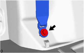
Install the floor anchor of the front seat outer belt assembly LH with the bolt.
- Torque:
- 42 N*m (428 kgf*cm, 31 ft.*lbf)
Check that the ELR locks.
With the front seat outer belt assembly LH installed to the vehicle, check that the belt locks when it is pulled out quickly.
73210
21.INSTALL FRONT SEAT OUTER BELT ASSEMBLY RH (FLOOR ANCHOR)
- HINT:
-
Use the same procedure described for the LH side.
73233
22.INSTALL OUTER LAP BELT ANCHOR COVER
- HINT:
-
Use the same procedure for the other side.
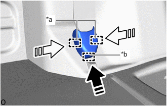
| *a | Guide A |
| *b | Guide B |
|
|
Install in this Direction (1) |

|
Install in this Direction (2) |
Attach the guide B in the installation direction (1) shown in the illustration.
Attach the guide A in the installation direction (2) shown in the illustration and install the outer lap belt anchor cover.
74680
23.INSTALL PILLAR ASSIST GRIP ASSEMBLY B (w/ Assist Grip)
74617A
24.INSTALL ASSIST GRIP PLUG (w/ Assist Grip)
25.INSTALL FRONT SEAT ASSEMBLY LH
26.INSTALL FRONT SEAT ASSEMBLY RH
for Separate Seat Type:
- HINT:
-
Use the same procedure described for the LH side.
for Fixed Bench Seat Type:
67914B
27.INSTALL FRONT DOOR SCUFF PLATE LH
67913B
28.INSTALL FRONT DOOR SCUFF PLATE RH
- HINT:
-
Use the same procedure described for the LH side.
67912A
29.INSTALL FRONT DOOR OUTSIDE SCUFF PLATE LH
67911B
30.INSTALL FRONT DOOR OUTSIDE SCUFF PLATE RH
- HINT:
-
Use the same procedure described for the LH side.
31.CONNECT CABLE TO NEGATIVE BATTERY TERMINAL (w/ Pretensioner and Force Limiter)
32. INITIALIZATION AFTER RECONNECTING BATTERY TERMINAL (w/ Pretensioner and Force Limiter)
- HINT:
-
When disconnecting and reconnecting the battery, there is an automatic learning function that completes learning when the respective system is used.
33. PERFORM DIAGNOSTIC SYSTEM CHECK (w/ Pretensioner and Force Limiter)
34.CHECK SRS WARNING LIGHT (w/ Pretensioner and Force Limiter)
35.INSPECT SEAT BELT WARNING SYSTEM (w/ Seat Belt Warning System)