LIGHTING (INT) LIGHTING SYSTEM Ambient Illumination Light Circuit
DESCRIPTION
The main body ECU (multiplex network body ECU) controls the operation of the following lights:
Footwell Light LH (No. 1 Interior Illumination Light Assembly)*
Footwell Light RH (No. 2 Interior Illumination Light Assembly)*
Glove Box Light Assembly*
Center Tray Illumination Light (No. 3 Interior Illumination Light Assembly)
Console Box Illumination Light (Console Box Illumination Light Assembly)*
Inside Handle Illumination Light RH (No. 1 Interior Illumination Light Assembly RH)*
Inside Handle Illumination Light LH (No. 1 Interior Illumination Light Assembly LH)*
*: w/ Footwell Light
WIRING DIAGRAM
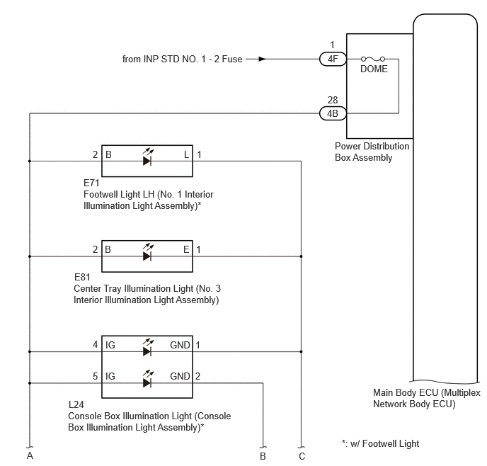
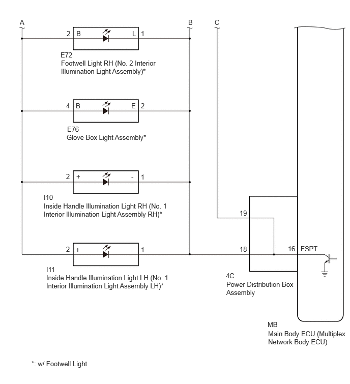
CAUTION / NOTICE / HINT
- NOTICE:
- ·
Inspect the fuses for circuits related to this system before performing the following procedure.
·Before replacing the main body ECU (multiplex network body ECU), refer to Service Bulletin.
PROCEDURE
- Result:
Result Proceed to w/o Footwell Light A w/ Footwell Light B
A
B
Perform the Active Test according to the display on the GTS.
- Body Electrical > Main Body > Active Test
-
Tester Display Measurement Item Control Range Diagnostic Note Front Footwell Lights Center Tray Illumination Light (No. 3 Interior Illumination Light Assembly) OFF or ON Operates when ignition switch is off and all doors are locked.
- Body Electrical > Main Body > Active Test
-
Tester Display Front Footwell Lights - 50004 449 22
- OK:
Center tray illumination light comes on.
- Result:
Proceed to OK NG
OK
NG
- Result:
Proceed to OK NG
OK
NG
Disconnect the 4F power distribution box assembly connector.
Measure the voltage according to the value(s) in the table below.
- Standard Voltage:
Tester Connection Condition Specified Condition 4F-1 - Body ground Ignition switch off 11 to 14 V
- Result:
Proceed to OK NG
OK
NG
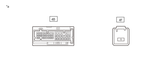
| *a | Component without harness connected
(Power Distribution Box Assembly) |
- | - |
Disconnect the 4B power distribution box assembly connector.
Measure the resistance according to the value(s) in the table below.
- Standard Resistance:
Tester Connection Condition Specified Condition 4F-1 - 4B-28 Always Below 1 Ω
- Result:
Proceed to OK NG
OK
NG
Disconnect the 4C power distribution box assembly connector.
Measure the resistance according to the value(s) in the table below.
- Standard Resistance:
Tester Connection Condition Specified Condition Click Location & Routing(E81)Location & Routingewd_type=routing;type=c;code=E81
E81-2 (B) - 4B-28 Always Below 1 Ω E81-1 (E) - 4C-19 Always Below 1 Ω E81-2 (B) or 4B-28 - Body ground Always 10 kΩ or higher E81-1 (E) or 4C-19 - Body ground Always 10 kΩ or higher
- Result:
Proceed to OK NG
OK
NG
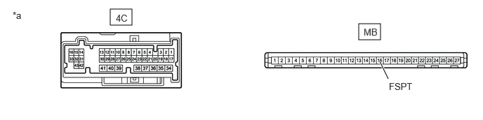
| *a | Component without harness connected
(Power Distribution Box Assembly) |
- | - |
Remove the main body ECU (multiplex network body ECU) from the power distribution box assembly.
Measure the resistance according to the value(s) in the table below.
- Standard Resistance:
Tester Connection Condition Specified Condition 4C-19 - MB-16 (FSPT) Always Below 1 Ω
- Result:
Proceed to OK NG
OK
NG
Perform the Active Test according to the display on the GTS.
- Body Electrical > Main Body > Active Test
-
Tester Display Measurement Item Control Range Diagnostic Note Front Footwell Lights ·Footwell Light (Interior Illumination Light Assembly)
·Glove Box Light Assembly
·Center Tray Illumination Light (No. 3 Interior Illumination Light Assembly)
·Console Box Illumination Light (Console Box Illumination Light Assembly)
·Inside Handle Illumination Light (No. 1 Interior Illumination Light Assembly)
OFF or ON Operates when ignition switch is off and all doors are locked.
- Body Electrical > Main Body > Active Test
-
Tester Display Front Footwell Lights - 50004 449 22
- OK:
Footwell lights, glove box light assembly, center tray illumination light, console box illumination light and inside handle illumination lights come on.
- Result:
Result Proceed to OK A NG (Footwell light LH does not come on) B NG (Footwell light RH does not come on) C NG (Glove box light assembly does not come on) D NG (Center tray illumination light does not come on) E NG (Console box illumination light does not come on) F NG (Inside handle illumination light LH does not come on) G NG (Inside handle illumination light RH does not come on) H NG (Footwell lights, glove box light assembly, center tray illumination light, console box illumination light and inside handle illumination lights do not come on) I
A
B
C
D
E
F
G
H
I
- Result:
Proceed to OK NG
OK
NG
Disconnect the 4B and 4C power distribution box assembly connectors.
Measure the resistance according to the value(s) in the table below.
- Standard Resistance:
Tester Connection Condition Specified Condition Click Location & Routing(E71)Location & Routingewd_type=routing;type=c;code=E71
Click Connector(E71)Instrument Panel>Instrument Panel Wire / Radio Wiring Sub-Assy / Telephone Computer Wire>No. 2 Interior Illumination Light Assembly LHewd_type=component;type=c;code=E71;pinno=2,1
E71-2 (B) - 4B-28 Always Below 1 Ω E71-1 (L) - 4C-19 Always Below 1 Ω E71-2 (B) or 4B-28 - Body ground Always 10 kΩ or higher E71-1 (L) or 4C-19 - Body ground Always 10 kΩ or higher
- Result:
Proceed to OK NG
OK
NG
| *a | Component without harness connected
(Power Distribution Box Assembly) |
- | - |
Remove the main body ECU (multiplex network body ECU) from the power distribution box assembly.
Measure the resistance according to the value(s) in the table below.
- Standard Resistance:
Tester Connection Condition Specified Condition 4C-19 - MB-16 (FSPT) Always Below 1 Ω
- Result:
Proceed to OK NG
OK
NG
- Result:
Proceed to OK NG
OK
NG
Disconnect the 4B and 4C power distribution box assembly connectors.
Measure the resistance according to the value(s) in the table below.
- Standard Resistance:
Tester Connection Condition Specified Condition Click Location & Routing(E72)Location & Routingewd_type=routing;type=c;code=E72
Click Connector(E72)Instrument Panel>Instrument Panel Wire / Radio Wiring Sub-Assy / Telephone Computer Wire>No. 2 Interior Illumination Light Assembly RHewd_type=component;type=c;code=E72;pinno=2,1
E72-2 (B) - 4B-28 Always Below 1 Ω E72-1 (L) - 4C-18 Always Below 1 Ω E72-2 (B) or 4B-28 - Body ground Always 10 kΩ or higher E72-1 (L) or 4C-18 - Body ground Always 10 kΩ or higher
- Result:
Proceed to OK NG
OK
NG
| *a | Component without harness connected
(Power Distribution Box Assembly) |
- | - |
Remove the main body ECU (multiplex network body ECU) from the power distribution box assembly.
Measure the resistance according to the value(s) in the table below.
- Standard Resistance:
Tester Connection Condition Specified Condition 4C-18 - MB-16 (FSPT) Always Below 1 Ω
- Result:
Proceed to OK NG
OK
NG
- Result:
Proceed to OK NG
OK
NG
Disconnect the 4B and 4C power distribution box assembly connectors.
Measure the resistance according to the value(s) in the table below.
- Standard Resistance:
Tester Connection Condition Specified Condition Click Location & Routing(E76)Location & Routingewd_type=routing;type=c;code=E76
Click Connector(E76)Instrument Panel>Instrument Panel Wire / Radio Wiring Sub-Assy / Telephone Computer Wire>Glove Box Light Assemblyewd_type=component;type=c;code=E76;pinno=4,2
E76-4 (B) - 4B-28 Always Below 1 Ω E76-2 (E) - 4C-18 Always Below 1 Ω E76-4 (B) or 4B-28 - Body ground Always 10 kΩ or higher E76-2 (E) or 4C-18 - Body ground Always 10 kΩ or higher
- Result:
Proceed to OK NG
OK
NG
| *a | Component without harness connected
(Power Distribution Box Assembly) |
- | - |
Remove the main body ECU (multiplex network body ECU) from the power distribution box assembly.
Measure the resistance according to the value(s) in the table below.
- Standard Resistance:
Tester Connection Condition Specified Condition 4C-18 - MB-16 (FSPT) Always Below 1 Ω
- Result:
Proceed to OK NG
OK
NG
- Result:
Proceed to OK NG
OK
NG
Disconnect the 4B and 4C power distribution box assembly connectors.
Measure the resistance according to the value(s) in the table below.
- Standard Resistance:
Tester Connection Condition Specified Condition Click Location & Routing(E81)Location & Routingewd_type=routing;type=c;code=E81
E81-2 (B) - 4B-28 Always Below 1 Ω E81-1 (E) - 4C-19 Always Below 1 Ω E81-2 (B) or 4B-28 - Body ground Always 10 kΩ or higher E81-1 (E) or 4C-19 - Body ground Always 10 kΩ or higher
- Result:
Proceed to OK NG
OK
NG
| *a | Component without harness connected
(Power Distribution Box Assembly) |
- | - |
Remove the main body ECU (multiplex network body ECU) from the power distribution box assembly.
Measure the resistance according to the value(s) in the table below.
- Standard Resistance:
Tester Connection Condition Specified Condition 4C-19 - MB-16 (FSPT) Always Below 1 Ω
- Result:
Proceed to OK NG
OK
NG
- Result:
Proceed to OK NG
OK
NG
Disconnect the 4B and 4C power distribution box assembly connectors.
Measure the resistance according to the value(s) in the table below.
- Standard Resistance:
Tester Connection Condition Specified Condition Click Location & Routing(L24)Location & Routingewd_type=routing;type=c;code=L24
Click Connector(L24)Instrument Panel>No. 2 Floor Wire>Console Box Illumination Light Assemblyewd_type=component;type=c;code=L24;pinno=4,5,1,2
L24-4 (IG) - 4B-28 Always Below 1 Ω L24-5 (IG) - 4B-28 Always Below 1 Ω L24-1 (GND) - 4C-19 Always Below 1 Ω L24-2 (GND) - 4C-18 Always Below 1 Ω L24-4 (IG) or 4B-28 - Body ground Always 10 kΩ or higher L24-5 (IG) or 4B-28 - Body ground Always 10 kΩ or higher L24-1 (GND) or 4C-19 - Body ground Always 10 kΩ or higher L24-2 (GND) or 4C-18 - Body ground Always 10 kΩ or higher
- Result:
Proceed to OK NG
OK
NG
| *a | Component without harness connected
(Power Distribution Box Assembly) |
- | - |
Remove the main body ECU (multiplex network body ECU) from the power distribution box assembly.
Measure the resistance according to the value(s) in the table below.
- Standard Resistance:
Tester Connection Condition Specified Condition 4C-18 - MB-16 (FSPT) Always Below 1 Ω 4C-19 - MB-16 (FSPT) Always Below 1 Ω
- Result:
Proceed to OK NG
OK
NG
- Result:
Proceed to OK NG
OK
NG
Disconnect the 4B and 4C power distribution box assembly connectors.
Measure the resistance according to the value(s) in the table below.
- Standard Resistance:
Tester Connection Condition Specified Condition Click Location & Routing(I11)Location & Routingewd_type=routing;type=c;code=I11
Click Connector(I11)Body>No. 2 Front Door Wire RH / No. 2 Front Door Wire LH>No. 1 Interior Illumination Light Assembly LHewd_type=component;type=c;code=I11;pinno=2,1
I11-2 (+) - 4B-28 Always Below 1 Ω I11-1 (-) - 4C-18 Always Below 1 Ω I11-2 (+) or 4B-28 - Body ground Always 10 kΩ or higher I11-1 (-) or 4C-18 - Body ground Always 10 kΩ or higher
- Result:
Proceed to OK NG
OK
NG
| *a | Component without harness connected
(Power Distribution Box Assembly) |
- | - |
Remove the main body ECU (multiplex network body ECU) from the power distribution box assembly.
Measure the resistance according to the value(s) in the table below.
- Standard Resistance:
Tester Connection Condition Specified Condition 4C-18 - MB-16 (FSPT) Always Below 1 Ω
- Result:
Proceed to OK NG
OK
NG
- Result:
Proceed to OK NG
OK
NG
Disconnect the 4B and 4C power distribution box assembly connectors.
Measure the resistance according to the value(s) in the table below.
- Standard Resistance:
Tester Connection Condition Specified Condition Click Location & Routing(I10)Location & Routingewd_type=routing;type=c;code=I10
Click Connector(I10)Body>No. 2 Front Door Wire RH / No. 2 Front Door Wire LH>No. 1 Interior Illumination Light Assembly RHewd_type=component;type=c;code=I10;pinno=2,1
I10-2 (+) - 4B-28 Always Below 1 Ω I10-1 (-) - 4C-18 Always Below 1 Ω I10-2 (+) or 4B-28 - Body ground Always 10 kΩ or higher I10-1 (-) or 4C-18 - Body ground Always 10 kΩ or higher
- Result:
Proceed to OK NG
OK
NG
| *a | Component without harness connected
(Power Distribution Box Assembly) |
- | - |
Remove the main body ECU (multiplex network body ECU) from the power distribution box assembly.
Measure the resistance according to the value(s) in the table below.
- Standard Resistance:
Tester Connection Condition Specified Condition 4C-18 - MB-16 (FSPT) Always Below 1 Ω
- Result:
Proceed to OK NG
OK
NG
Disconnect the 4F power distribution box assembly connector.
Measure the voltage according to the value(s) in the table below.
- Standard Voltage:
Tester Connection Condition Specified Condition 4F-1 - Body ground Ignition switch off 11 to 14 V
- Result:
Proceed to OK NG
OK
NG
| *a | Component without harness connected
(Power Distribution Box Assembly) |
- | - |
Disconnect the 4B power distribution box assembly connector.
Measure the resistance according to the value(s) in the table below.
- Standard Resistance:
Tester Connection Condition Specified Condition 4F-1 - 4B-28 Always Below 1 Ω
- Result:
Proceed to OK NG
OK
NG
Disconnect the E71 footwell light LH (No. 1 interior illumination light assembly) connector.
Disconnect the E72 footwell light RH (No. 2 interior illumination light assembly) connector.
Disconnect the E76 glove box light assembly connector.
Disconnect the E81 center tray illumination light (No. 3 interior illumination light assembly) connector.
Disconnect the L24 console box illumination light (console box illumination light assembly) connector.
Disconnect the I11 inside handle illumination light LH (No. 1 interior illumination light assembly LH) connector.
Disconnect the I10 inside handle illumination light RH (No. 1 interior illumination light assembly RH) connector.
Measure the resistance according to the value(s) in the table below.
- Standard Resistance:
- Result:
Proceed to OK NG
OK
NG
Disconnect the 4C power distribution box assembly connector.
Measure the resistance according to the value(s) in the table below.
- Standard Resistance:
- Result:
Proceed to OK NG
OK
NG
| *a | Component without harness connected
(Power Distribution Box Assembly) |
- | - |
Remove the main body ECU (multiplex network body ECU) from the power distribution box assembly.
Measure the resistance according to the value(s) in the table below.
- Standard Resistance:
Tester Connection Condition Specified Condition 4C-18 - MB-16 (FSPT) Always Below 1 Ω 4C-19 - MB-16 (FSPT) Always Below 1 Ω
- Result:
Proceed to OK NG
OK
NG