NR Series ENGINE CONTROL SFI SYSTEM VC Output Circuit
DESCRIPTION
The ECM constantly generates a 5 V power source voltage from the battery voltage supplied to the +B, +B2 (BATT) terminals to operate the microprocessor. The ECM also provides this power to the sensors through the VC output circuit.
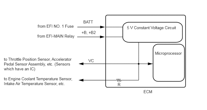
When the VC circuit has a short circuit, the microprocessor in the ECM and sensors that are supplied power through the VC circuit are deactivated because power is not supplied from the VC circuit. When the system is in this condition, it will not start.
WIRING DIAGRAM
For the circuit diagram of the ECM power source refer to the ECM Power Source Circuit
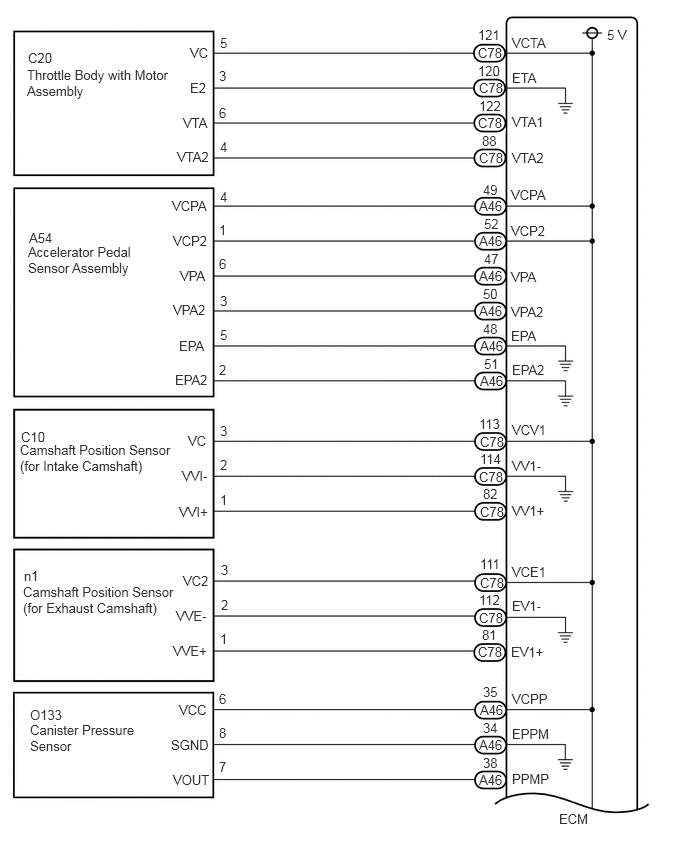
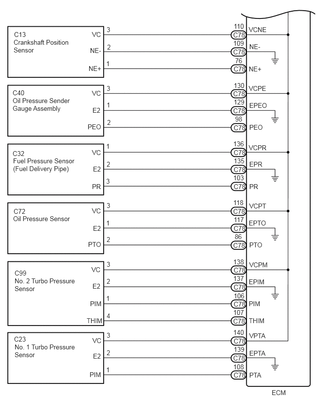
VC Output Circuit
CAUTION / NOTICE / HINT
- NOTICE:
-
Check the fuses for circuits related to this system before performing the following inspection procedure.
PROCEDURE
Connect the GTS to the DLC3.
Turn the ignition switch to ON.
Turn the GTS on.
Check the communication between the GTS and ECM.
- HINT:
-
It can be checked using the "Engine" item of the Data List.
- Result:
Result Proceed to Communication is not possible A Communication is possible B
A
B
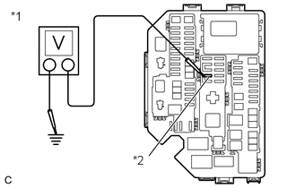
| *1 | No. 1 Engine Room Relay Block and No. 1 Junction Block Assembly |
| *2 | EFI NO. 2 Fuse |
Turn the ignition switch to ON.
Measure the voltage according to the value(s) in the table below.
- Standard Voltage:
Tester Connection Condition Specified Condition 1 (EFI NO. 2 fuse) - Body ground Ignition switch ON 11 to 14 V
- HINT:
- ·
Check the fuse with it installed to the No. 1 engine room relay block and No. 1 junction block assembly.
·If the result is not as specified, since current is not flowing to the +B and +B2 terminals of the ECM, the system may not be started.
- Result:
Proceed to OK NG
OK
NG
Disconnect the throttle body with motor assembly connector.
Turn the ignition switch to ON.
Turn the GTS on.
Check the communication between the GTS and ECM.
- HINT:
-
It can be checked using the "Engine" item of the Data List.
- Result:
Result Proceed to Communication is not possible A Communication is possible B
- HINT:
-
Perform "Inspection After Repair" after replacing the throttle body with motor assembly.
A
B
Disconnect the accelerator pedal sensor assembly connector.
Turn the ignition switch to ON.
Turn the GTS on.
Check the communication between the GTS and ECM.
- HINT:
-
It can be checked using the "Engine" item of the Data List.
- Result:
Result Proceed to Communication is not possible A Communication is possible B
A
B
Disconnect the camshaft position sensor (for intake camshaft) connector.
Turn the ignition switch to ON.
Turn the GTS on.
Check the communication between the GTS and ECM.
- HINT:
-
It can be checked using the "Engine" item of the Data List.
- Result:
Result Proceed to Communication is not possible A Communication is possible B
A
B
Disconnect the camshaft position sensor (for exhaust camshaft) connector.
Turn the ignition switch to ON.
Turn the GTS on.
Check the communication between the GTS and ECM.
- HINT:
-
It can be checked using the "Engine" item of the Data List.
- Result:
Result Proceed to Communication is not possible A Communication is possible B
A
B
Disconnect the crankshaft position sensor connector.
Turn the ignition switch to ON.
Turn the GTS on.
Check the communication between the GTS and ECM.
- HINT:
-
It can be checked using the "Engine" item of the Data List.
- Result:
Result Proceed to Communication is not possible A Communication is possible B
A
B
Disconnect the oil pressure sensor connector.
Turn the ignition switch to ON.
Turn the GTS on.
Check the communication between the GTS and ECM.
- HINT:
-
It can be checked using the "Engine" item of the Data List.
- Result:
Result Proceed to Communication is not possible A Communication is possible B
A
B
Click hereDrivetrain>K313 (CVT)>OIL PRESSURE SENSOR>REMOVAL201906,999999,_52,_080728,_0392271,RM100000001HPB1,
Disconnect the No. 1 turbo pressure sensor connector.
Turn the ignition switch to ON.
Turn the GTS on.
Check the communication between the GTS and ECM.
- HINT:
-
It can be checked using the "Engine" item of the Data List.
- Result:
Result Proceed to Communication is not possible A Communication is possible B
A
B
Disconnect the No. 2 turbo pressure sensor connector.
Turn the ignition switch to ON.
Turn the GTS on.
Check the communication between the GTS and ECM.
- HINT:
-
It can be checked using the "Engine" item of the Data List.
- Result:
Result Proceed to Communication is not possible A Communication is possible B
A
B
Disconnect the oil pressure sender gauge assembly connector.
Turn the ignition switch to ON.
Turn the GTS on.
Check the communication between the GTS and ECM.
- HINT:
-
It can be checked using the "Engine" item of the Data List.
- Result:
Result Proceed to Communication is not possible A Communication is possible B
A
B
Disconnect the fuel pressure sensor connector.
Turn the ignition switch to ON.
Turn the GTS on.
Check the communication between the GTS and ECM.
- HINT:
-
It can be checked using the "Engine" item of the Data List.
- Result:
Result Proceed to Communication is not possible A Communication is possible B
- HINT:
-
Perform "Inspection After Repair" after replacing the fuel delivery pipe.
A
B
Disconnect the canister pump module connector.
Turn the ignition switch to ON.
Turn the GTS on.
Check the communication between the GTS and ECM.
- HINT:
-
It can be checked using the "Engine" item of the Data List.
- Result:
Result Proceed to Communication is not possible A Communication is possible B
A
B
Disconnect the throttle body with motor assembly connector.
Disconnect the accelerator pedal sensor assembly connector.
Disconnect the camshaft position sensor (for intake camshaft) connector.
Disconnect the camshaft position sensor (for exhaust camshaft) connector.
Disconnect the crankshaft position sensor connector.
Disconnect the oil pressure sensor connector.
Disconnect the No. 1 turbo pressure sensor connector.
Disconnect the No. 2 turbo pressure sensor connector.
Disconnect the oil pressure sender gauge assembly connector.
Disconnect the fuel pressure sensor connector.
Disconnect the canister pump module connector.
Disconnect the ECM connectors.
Measure the resistance according to the value(s) in the table below.
- Standard Resistance:
Tester Connection Condition Specified Condition C78-121 (VCTA) - Body ground Always 10 kΩ or higher A46-49 (VCPA) - Body ground Always 10 kΩ or higher A46-52 (VCP2) - Body ground Always 10 kΩ or higher C78-113 (VCV1) - Body ground Always 10 kΩ or higher C78-111 (VCE1) - Body ground Always 10 kΩ or higher C78-110 (VCNE) - Body ground Always 10 kΩ or higher C78-118 (VCPT) - Body ground Always 10 kΩ or higher C78-140 (VPTA) - Body ground Always 10 kΩ or higher C78-138 (VCPM) - Body ground Always 10 kΩ or higher C78-130 (VCPE) - Body ground Always 10 kΩ or higher C78-136 (VCPR) - Body ground Always 10 kΩ or higher A46-35 (VCPP) - Body ground Always 10 kΩ or higher
Remove the EFI-MAIN NO. 2 relay from the No. 1 engine room relay block and No. 1 junction block assembly.
- HINT:
-
Remove the EFI-MAIN NO. 2 relay connected between the checked terminals as the coil inside the relay influences the measurement value.
Measure the resistance according to the value(s) in the table below.
- Standard Resistance:
Tester Connection Condition Specified Condition A46-2 (+B) - 1 (EFI NO. 2 fuse) Always Below 1 Ω A46-3 (+B2) - 1 (EFI NO. 2 fuse) Always Below 1 Ω A46-2 (+B) - Body ground Always 10 kΩ or higher A46-3 (+B2) - Body ground Always 10 kΩ or higher
- Result:
Proceed to OK NG
OK
NG