NR Series ENGINE CONTROL ECM REMOVAL
CAUTION / NOTICE / HINT
The necessary procedures (adjustment, calibration, initialization or registration) that must be performed after parts are removed and installed, or replaced during ECM removal/installation are shown below.
| Replaced Part or Performed Procedure | Necessary Procedure | Effect/Inoperative Function when Necessary Procedure not Performed | Link |
|---|---|---|---|
| Replacement of ECM | Perform Vehicle Identification Number (VIN) or frame number registration | DTC is stored | ( 201906,999999,_51,_080777,_0393969,RM100000001I1RD,) 201906,999999,_51,_080777,_0393969,RM100000001I1RD,)
|
1.
Reset memory 2.
Deceleration sensor zero point calibration 3.
CVT oil pressure calibration |
·
Large shift shock ·
Deterioration of fuel efficiency |
(201906,999999,_52,_080728,_0392261,RM100000001HP98,)
|
|
| Code registration (Immobiliser system) | Engine start | See Service Bulletin for the registration method |
- NOTICE:
- ·
If the ECM has been struck or dropped, replace it.
·Perform the Vehicle Identification Number (VIN) or frame number registration when replacing the ECM.
·When replacing the ECM, use the GTS to save "Heavy Knock History" and then upload it to the new ECM.
- HINT:
-
When the cable is disconnected / reconnected to the battery terminal, systems temporarily stop operating. However, each system has a function that completes learning the first time the system is used.
Learning completes when vehicle is driven Effect/Inoperative Function when Necessary Procedure not Performed Necessary Procedure Link Stop and Start System Idle the engine for approximately 5 to 60 minutes or drive the vehicle until stop and start control is permitted ( 201906,999999,_51,_080774,_0393362,RM100000001HXHC,)
Pre-collision System Perform steering sensor zero point calibration ( 202304,999999,_95,_139716,_0601175,RM100000002BFOE,)
Lane Tracing Assist System
PROCEDURE

 1. PRECAUTION
- NOTICE:
-
After turning the ignition switch off, waiting time may be required before disconnecting the cable from the negative (-) battery terminal.
2.DISCONNECT CABLE FROM NEGATIVE BATTERY TERMINAL
53289A
3.REMOVE RADIATOR SUPPORT OPENING COVER
17751
4.REMOVE INLET NO. 1 AIR CLEANER
17705
5.REMOVE AIR CLEANER CAP SUB-ASSEMBLY
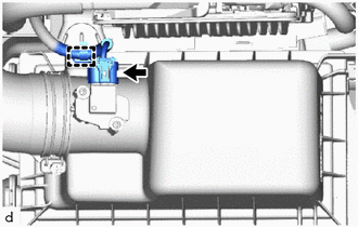
Disconnect the mass air flow meter sub-assembly connector.
Disengage the clamp from the air cleaner cap sub-assembly.
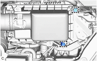
Disengage the 2 clamps.
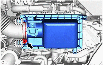
Disengage the 2 guides to separate the air cleaner cap sub-assembly from the air cleaner case sub-assembly.
Loosen the hose clamp and remove the air cleaner cap sub-assembly from the air cleaner hose.
17701
6.REMOVE AIR CLEANER CASE SUB-ASSEMBLY
89661
7.REMOVE ECM
- HINT:
-
When replacing the ECM, use the GTS to save "Heavy Knock History" and then upload it to the new ECM.
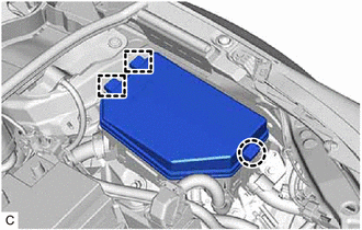
Disengage the claw and 2 guides to remove the No. 1 relay block cover from the No. 1 engine room relay block and No. 1 junction block assembly.
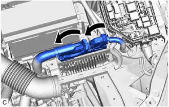
Raise the 2 levers while pushing the locks on the levers, and disconnect the 2 ECM connectors.
- NOTICE:
-
After disconnecting the ECM connectors, make sure that dirt, water or other foreign matter does not contact the connecting parts of the ECM connectors.
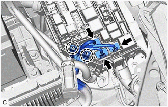
Disconnect the 3 connectors from the No. 1 engine room relay block and No. 1 junction block assembly.
Disengage the 2 claws to separate the engine wire from the No. 1 engine room relay block and No. 1 junction block assembly.
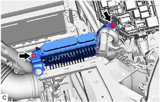
Remove the bolt, nut and ECM.
- NOTICE:
-
If the ECM has been struck or dropped, replace it.
89667E
8.REMOVE NO. 1 ECM BRACKET
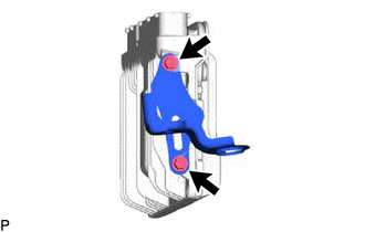
Remove the 2 screws and No. 1 ECM bracket from the ECM.
89668
9.REMOVE NO. 2 ECM BRACKET
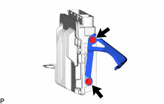
Remove the 2 screws and No. 2 ECM bracket from the ECM.