7GR-FKS FUEL FUEL PUMP REMOVAL
CAUTION / NOTICE / HINT
The necessary procedures (adjustment, calibration, initialization or registration) that must be performed after parts are removed and installed, or replaced during fuel pump with filter assembly removal/installation are shown below.
| Replaced Part or Performed Procedure | Necessary Procedure | Effect/Inoperative Function when Necessary Procedure not Performed | Link |
|---|---|---|---|
| Battery terminal is disconnected/reconnected | Memorize steering angle neutral point | Parking assist monitor system | ( 201902,999999,_56,_079315,_0385736,RM100000001GNRA,) 201902,999999,_56,_079315,_0385736,RM100000001GNRA,)
|
| Panoramic view monitor system | (201906,999999,_56,_079315,_0396274,RM100000001IGR3,)
|
||
| Replacement of fuel pump with filter assembly | Inspection after repair | ·
Poor idle, etc. ·
Engine start function, etc. |
(201902,999999,_51,_078720,_0381907,RM100000001G2VV,)
|
- HINT:
-
When the cable is disconnected / reconnected to the battery terminal, systems temporarily stop operating. However, each system has a function that completes learning the first time the system is used.
- ·
Learning completes when vehicle is driven
Effect/Inoperative when not Performed Necessary Procedures Link Lane control system Drive the vehicle straight ahead at 15 km/h (10 mph) or more for 1 second or more. ( 201902,999999,_58,_078886,_0382740,RM100000001G6XB,)
Pre-collision system
·Learning completes when vehicle is operated normally
Effect/Inoperative when not Performed Necessary Procedures Link Power slide door system Fully close the slide door by hand.
- HINT:
-
Initialization is not necessary if the above procedures are performed while the slide door is closed.
( 201902,999999,_59,_078503,_0381017,RM100000001FWXM,)
Air conditioning system After the ignition switch is turned to ON, the servo motor standard position is recognized. -
- CAUTION:
- ·
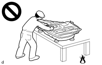
Never perform work on fuel system components near any possible ignition sources.
·Vaporized fuel could ignite, resulting in a serious accident.
·
Do not perform work on fuel system components without first disconnecting the cable from the negative (-) battery terminal.
·Sparks could cause vaporized fuel to ignite, resulting in a serious accident.
- NOTICE:
-
Do not disconnect the tube shown in the illustration when disassembling the fuel suction tube with pump and gauge assembly. Doing so will cause reassembly of the fuel suction tube with pump and gauge assembly to be impossible as the tube is pressed into the fuel suction plate sub-assembly.
PROCEDURE

 1. PRECAUTION
- NOTICE:
-
After turning the ignition switch is turned off, there may be a waiting time before disconnecting the negative (-) battery terminal.
2. DISCHARGE FUEL SYSTEM PRESSURE
3.DISCONNECT CABLE FROM NEGATIVE BATTERY TERMINAL
4.REMOVE REAR SEAT ASSEMBLY (except Wagon)
for Commuter, 3-Passenger Seat with 2-Point Type Seat Belt and Headrest:
for Commuter, 3-Passenger Seat with 2-Point Type Seat Belt without Headrest:
for Commuter, 3-Passenger Seat with 3-Point Type Seat Belt:
for Commuter, 4-Passenger Seat:
for Commuter, Single-Passenger Seat with 2-Point Type Seat Belt:
for Commuter, Single-Passenger Seat with 3-Point Type Seat Belt:
for Commuter, 2-Passenger Seat with 3-Point Type Seat Belt:
for Commuter, 2-Passenger Seat with 2-Point Type Seat Belt and Headrest:
for Commuter, 2-Passenger Seat with 2-Point Type Seat Belt without Headrest:
58759A
5.REMOVE FUEL TANK INSPECTION HOLE COVER
for Wagon:
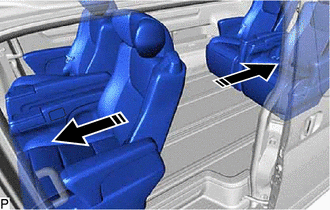
Slide the 1st row rear seat assembly LH forward and the 2nd row rear assembly LH backward so that the floor carpet and floor silencer can be folded back.
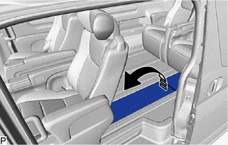
Fold back the rear floor carpet and rear floor silencer.
except Wagon:
Fold back the rear floor carpet.
Remove the rear floor board.
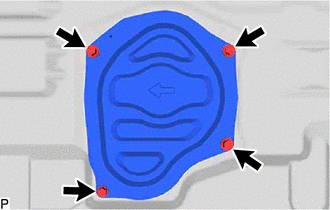
Remove the 4 bolts and fuel tank inspection hole cover.
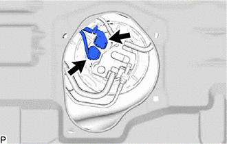
Disconnect the 2 connectors from the fuel suction with pump and gauge tube assembly.
77027
6.DISCONNECT NO. 2 FUEL EVAPORATION TUBE SUB-ASSEMBLY
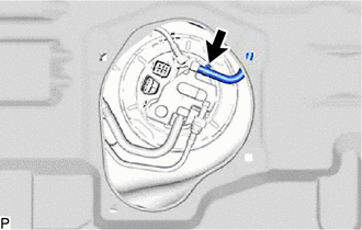
Slide the clamp and disconnect the No. 2 fuel evaporation tube sub-assembly from the fuel suction with pump and gauge tube assembly.
77754B
7.DISCONNECT CHARCOAL CANISTER OUTLET HOSE
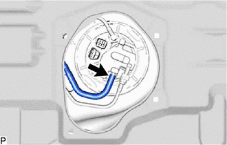
Disconnect the charcoal canister outlet hose from the fuel suction with pump and gauge tube assembly.
8.DISCONNECT FUEL TANK EVAP TUBE SUB-ASSEMBLY
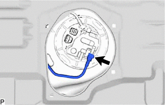
Disconnect the fuel tank evap tube sub-assembly from the fuel suction with pump and gauge tube assembly.
77209C
9.DISCONNECT FUEL TANK MAIN TUBE SUB-ASSEMBLY

| *1 | Tube Joint Clip |
| *2 | Fuel Tank Main Tube Sub-assembly |
| *a | Nylon Tube |
| *b | Fuel Tube Joint |
| *c | Plate Sub-assembly |
| *d | O-ring |

|
Pull off |

|
Pull off |
Remove the tube joint clip, and pull off the fuel tube joint of the fuel tank main tube sub-assembly.
- NOTICE:
- ·
Remove any foreign matter on the fuel tube joint before performing this work.
·Do not scratch or allow any foreign matter to get on the parts when disconnecting them as the fuel tube connector has O-rings that seal the pipe (fuel pipe).
·Be sure to disconnect the fuel tube joint by hand.
·Do not bend, twist, pinch or kink the nylon tube.
·Cover the disconnected fuel tube joint with a plastic bag to prevent damage and contamination.
·If the fuel tube joint and fuel suction plate sub-assembly are stuck, push and pull to release them.
77020A
10.REMOVE FUEL SUCTION WITH PUMP AND GAUGE TUBE ASSEMBLY
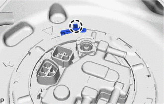
Detach the claw and remove the No. 1 fuel tube clamp from the fuel pump gauge retainer.
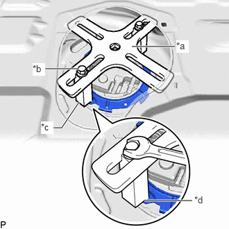
| *a | SST (Plate) |
| *b | SST (Bolt) |
| *c | SST (Claw) |
| *d | Insertion Point |
Remove the fuel pump gauge retainer.
Temporarily install SST (plate) and SST (claw) to the fuel pump gauge retainer.
- SST
- 09808-14031 (09808-01030, 09808-01090)
09808-01110
- HINT:
-
Securely insert the ends of SST (claw) into the insertion points in the fuel pump gauge retainer.
While firmly pressing SST (claw) into the insertion points in the fuel pump gauge retainer, tighten SST (bolt).
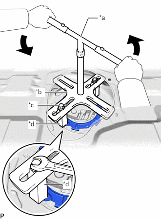
| *a | SST (Handle) |
| *b | SST (Plate) |
| *c | SST (Bolt) |
| *d | SST (Claw) |
Install SST (handle) to SST (plate).
- SST
- 09808-14031 (09808-01010)
09808-01110
Lightly press down on SST to prevent it from separating from the fuel pump gauge retainer. While pressing down on SST, rotate SST (handle) slowly to loosen the fuel pump gauge retainer.
- NOTICE:
- ·
Do not use any tools other than specified in this operation as this may result in damage to the fuel pump gauge retainer or fuel tank assembly.
·Do not press down on SST excessively as this may make the fuel pump gauge retainer hard to rotate, and may damage components.
·Make sure to rotate SST (handle) horizontally. If it is rotated at an angle, SST may come off.
·Do not spin SST too fast or use an impact wrench as this may result in damage to components.
·If SST comes off of the fuel pump gauge retainer, loosen SST (bolt) and reinstall SST.
While pressing down on the fuel suction with pump and gauge tube assembly, remove the fuel pump gauge retainer.
Remove the fuel suction with pump and gauge tube assembly from the fuel tank assembly.
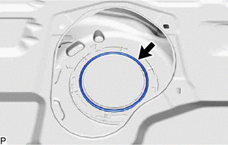
Remove the gasket from the fuel tank assembly.