THEFT DETERRENT / KEYLESS ENTRY ENTRY AND START SYSTEM(for Start Function) Power Source Mode does not Change to ON (IG and ACC)
DESCRIPTION
When the engine switch cannot be turned on (ACC) or on (IG), there may be a malfunction in interior certification, or the ACC relay or IG relay system. If interior certification does not succeed, the certification ECU (smart key ECU assembly) may be malfunctioning, or communication may not be possible between the No. 1 indoor electrical key antenna assembly (front floor), No. 1 indoor electrical key antenna assembly (center front floor), No. 1 indoor electrical key antenna assembly (center rear floor), No. 1 indoor electrical key antenna assembly (rear LH floor) or No. 1 indoor electrical key antenna assembly (rear RH floor), the electrical key transmitter sub-assembly, and the door control receiver.
When the electrical key transmitter sub-assembly is brought into the cabin, the key ID code sent from the electrical key transmitter sub-assembly and the key ID code stored in the certification ECU (smart key ECU assembly) are certified. If these codes do not match and certification fails, the engine switch cannot be turned on (ACC) or on (IG).
When the door is unlocked and the electrical key transmitter sub-assembly is brought into the cabin, the certification ECU (smart key ECU assembly) activates the indoor electrical key antenna and forms a detection area. When the electrical key transmitter sub-assembly is recognized inside the detection area, it returns the key ID code. This is received by the door control receiver, which then sends it to the certification ECU (smart key ECU assembly).
| Problem Symptom | Data List and Active Test |
|---|---|
| Power source mode does not change to on (IG) or on (ACC) | Power Source Control
·
Start Switch1 ·
Start Switch2 ·
IG Relay Monitor (Inside) ·
ACC Relay Monitor ·
IG Relay Monitor (Outside) ·
Latch Circuit ·
Power Supply Condition |
WIRING DIAGRAM
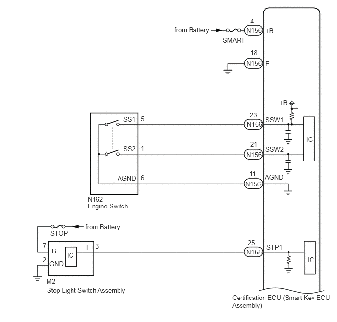
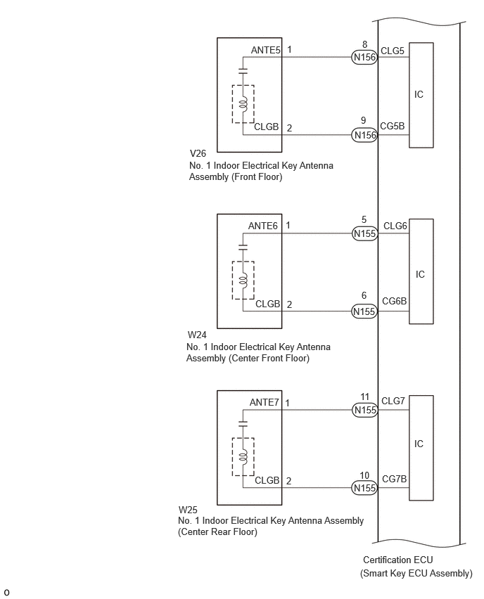

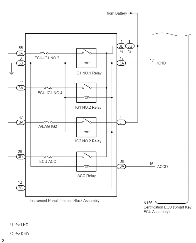
CAUTION / NOTICE / HINT
- NOTICE:
- ·
When using the GTS with the engine switch off, connect the GTS to the DLC3 and turn a courtesy light switch on and off at intervals of 1.5 seconds or less until communication between the GTS and the vehicle begins. Then select Model Code "KEY REGIST" under manual mode and enter the following menus: Body Electrical / Entry&Start. While using the GTS, periodically turn a courtesy light switch on and off at intervals of 1.5 seconds or less to maintain communication between the GTS and the vehicle.
·Make sure that no DTCs are output. If any DTCs are output, proceed to Diagnostic Trouble Code Chart.
·If the entry and start system (for Start Function) has been canceled, enable the system before performing troubleshooting.
·Inspect the fuses of circuits related to this system before performing the following procedure.
·Before replacing the certification ECU (smart key ECU assembly) or an electrical key transmitter sub-assembly, refer to the Service Bulletin.
·After completing repairs, confirm that the problem does not recur.
·After repair, confirm that no DTCs are output by performing "DTC Output Confirmation Operation".
·An antenna coil is connected between the terminals of the indoor electrical key antenna.
·The door control receiver is also involved in interior certification.
- HINT:
- ·
If interior certification does not succeed, the History of Reason for Operation may remain in the certification ECU (smart key ECU assembly).
·If the operation history remains, refer to the history table to determine the conditions and narrow down any trouble areas.
- Body Electrical > Entry&Start > Utility
-
Tester Display Operation History - 50005 125 52
PROCEDURE
Get into the vehicle while carrying the electrical key transmitter sub-assembly that has already been registered.
Change the shift state to park (P).
Check that the power source mode changes when the engine switch is pressed without depressing the brake pedal.
- Result:
Result Proceed to Power source mode does not change when the electrical key transmitter sub-assembly is inside the push-button start function operation range only for the front side A Power source mode does not change when the electrical key transmitter sub-assembly is inside the push-button start function operation range only for the center front floor side B Power source mode does not change when the electrical key transmitter sub-assembly is inside the push-button start function operation range only for the center rear floor side C Power source mode does not change when the electrical key transmitter sub-assembly is inside the push-button start function operation range only for the rear RH floor side D Power source mode does not change when the electrical key transmitter sub-assembly is inside the push-button start function operation range only for the rear LH floor side E Power source mode does not change when the electrical key transmitter sub-assembly is inside any push-button start function operation range F
A
B
C
E
F
D
Install the transmitter battery to the electrical key transmitter sub-assembly.
Bring the electrical key transmitter sub-assembly near the No. 1 indoor electrical key antenna assembly (front floor) and perform an entry and start system check.
- NOTICE:
-
Communication may not be possible if the electrical key transmitter sub-assembly is within 0.2 m (0.656 ft.) of the No. 1 indoor electrical key antenna assembly (front floor).
- HINT:
- ·
As the effect of wave interference decreases by moving the electrical key transmitter sub-assembly close to each indoor electrical key antenna assembly, it may be possible to check whether wave interference is the cause of the problem.
·If the inspection result is that the problem only occurs in certain locations or at certain times of day, the possibility of wave interference is high. Also, added vehicle components may cause wave interference. If installed, remove them and perform the operation check.
·There may be wave interference if the vehicle is near broadcasting antennas, large video displays, wireless garage door opener systems, wireless security cameras, home security systems, etc. In this case, move the vehicle to a different location and check if there is any improvement.
- OK:
The engine starts when the electrical key transmitter sub-assembly is held near each indoor electrical key antenna assembly and the engine switch is pressed with the brake pedal depressed.
- Result:
Proceed to OK NG
OK
NG
Connect the GTS to the DLC3.
Turn the engine switch on (IG).
Turn the GTS on.
Enter the following menus: Body Electrical / Entry&Start / Utility / Communication Check(Key Diag Mode).
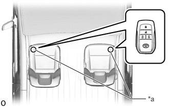
| *a | Inspection Point |
Check the No. 1 indoor electrical key antenna assembly (front floor).
When the electrical key transmitter sub-assembly is at either inspection point, check that the buzzer sounds.
- HINT:
- ·
Select either channel 1 or channel 2 and perform the key diagnostic mode inspection for each channel.
·If the buzzer sounds with [CH1] displayed but not with [CH2], the electrical key transmitter sub-assembly cannot be detected by channel 2 due to a malfunction, such as wave interference.
·It is possible to check which No. 1 indoor electrical key antenna assembly (front floor) is operating by the sounding of the buzzer.
·When the buzzer does not sound for No. 1 indoor electrical key antenna assembly (front floor), it can be judged that the certification ECU (smart key ECU assembly), which controls the No. 1 indoor electrical key antenna assembly (front floor), is malfunctioning.
- Body Electrical > Entry&Start > Utility
-
Tester Display Communication Check(Key Diag Mode) - 50005 125 143
- Result:
Result Proceed to The buzzer sounds A The buzzer does not sound B
A
B
Disconnect the N156 certification ECU (smart key ECU assembly) connector.
Disconnect the V26 No. 1 indoor electrical key antenna assembly (front floor) connector.
Measure the resistance according to the value(s) in the table below.
- Standard Resistance:
Tester Connection Condition Specified Condition N156-8 (CLG5) - V26-1 (ANTE5) Always Below 1 Ω N156-9 (CG5B) - V26-2 (CLGB) Always Below 1 Ω N156-8 (CLG5) or V26-1 (ANTE5) - Other terminals and body ground Always 10 kΩ or higher N156-9 (CG5B) or V26-2 (CLGB) - Other terminals and body ground Always 10 kΩ or higher
Reconnect the N156 certification ECU (smart key ECU assembly) connector.
- Result:
Proceed to OK NG
OK
NG
Using an oscilloscope, check the waveform.
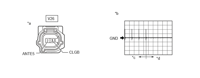
| *a | Front view of wire harness connector
(to No. 1 Indoor Electrical Key Antenna Assembly (Front Floor)) |
*b | Waveform |
| *c | For 30 seconds after closing any door | *d | After 30 seconds or more have elapsed since any door closed |
- OK:
Tester Connection Condition Tool Setting Specified Condition V26-1 (ANTE5) - V26-2 (CLGB) Procedure:
1.Engine switch off
2.Electrical key transmitter sub-assembly not inside vehicle
3.Within 30 seconds of closing any door
2 V/DIV., 500 ms./DIV. Pulse generation
(See waveform)
- Result:
Proceed to OK NG
OK
NG
Install the transmitter battery to the electrical key transmitter sub-assembly.
Bring the electrical key transmitter sub-assembly near the No. 1 indoor electrical key antenna assembly (center front floor) and perform an entry and start system check.
- NOTICE:
-
Communication may not be possible if the electrical key transmitter sub-assembly is within 0.2 m (0.656 ft.) of the center of the No. 1 indoor electrical key antenna assembly (center front floor).
- HINT:
- ·
As the effect of wave interference decreases by moving the electrical key transmitter sub-assembly close to each indoor electrical key antenna assembly, it may be possible to check whether wave interference is the cause of the problem.
·If the inspection result is that the problem only occurs in certain locations or at certain times of day, the possibility of wave interference is high. Also, added vehicle components may cause wave interference. If installed, remove them and perform the operation check.
·There may be wave interference if the vehicle is near broadcasting antennas, large video displays, wireless garage door opener systems, wireless security cameras, home security systems, etc. In this case, move the vehicle to a different location and check if there is any improvement.
- OK:
The engine starts when the electrical key transmitter sub-assembly is held near each indoor electrical key antenna assembly and the engine switch is pressed with the brake pedal depressed.
- Result:
Proceed to OK NG
OK
NG
Connect the GTS to the DLC3.
Turn the engine switch on (IG).
Turn the GTS on.
Enter the following menus: Body Electrical / Entry&Start / Utility / Communication Check(Key Diag Mode).
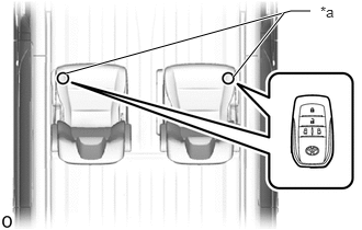
| *a | Inspection Point |
Check the No. 1 indoor electrical key antenna assembly (center front floor).
When the electrical key transmitter sub-assembly is at either inspection point, check that the buzzer sounds.
- HINT:
- ·
Select either channel 1 or channel 2 and perform the key diagnostic mode inspection for each channel.
·If the buzzer sounds with [CH1] displayed but not with [CH2], the electrical key transmitter sub-assembly cannot be detected by channel 2 due to a malfunction, such as wave interference.
·It is possible to check which No. 1 indoor electrical key antenna assembly (center front floor) is operating by the sounding of the buzzer.
·When the buzzer does not sound for No. 1 indoor electrical key antenna assembly (center front floor), it can be judged that the certification ECU (smart key ECU assembly), which controls the No. 1 indoor electrical key antenna assembly (center front floor), is malfunctioning.
- Body Electrical > Entry&Start > Utility
-
Tester Display Communication Check(Key Diag Mode) - 50005 125 143
- Result:
Result Proceed to The buzzer sounds A The buzzer does not sound B
A
B
Disconnect the N155 certification ECU (smart key ECU assembly) connector.
Disconnect the W24 No. 1 indoor electrical key antenna assembly (center front floor) connector.
Measure the resistance according to the value(s) in the table below.
- Standard Resistance:
Tester Connection Condition Specified Condition N155-5 (CLG6) - W24-1 (ANTE6) Always Below 1 Ω N155-6 (CG6B) - W24-2 (CLGB) Always Below 1 Ω N155-5 (CLG6) or W24-1 (ANTE6) - Other terminals and body ground Always 10 kΩ or higher N155-6 (CG6B) or W24-2 (CLGB) - Other terminals and body ground Always 10 kΩ or higher
Reconnect the N155 certification ECU (smart key ECU assembly) connector.
- Result:
Proceed to OK NG
OK
NG
Using an oscilloscope, check the waveform.
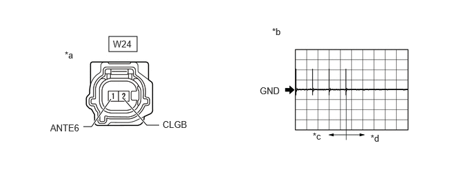
| *a | Front view of wire harness connector
(to No. 1 Indoor Electrical Key Antenna Assembly (Center Front Floor)) |
*b | Waveform |
| *c | For 30 seconds after closing any door | *d | After 30 seconds or more have elapsed since any door closed |
- OK:
Tester Connection Condition Tool Setting Specified Condition W24-1 (ANTE6) - W24-2 (CLGB) Procedure:
1.Engine switch off
2.Electrical key transmitter sub-assembly not inside vehicle
3.Within 30 seconds of closing any door
2 V/DIV., 500 ms./DIV. Pulse generation
(See waveform)
- Result:
Proceed to OK NG
OK
NG
Install the transmitter battery to the electrical key transmitter sub-assembly.
Bring the electrical key transmitter sub-assembly near the No. 1 indoor electrical key antenna assembly (center rear floor) and perform an entry and start system check.
- NOTICE:
-
Communication may not be possible if the electrical key transmitter sub-assembly is within 0.2 m (0.656 ft.) of the center of the No. 1 indoor electrical key antenna assembly (center rear floor).
- HINT:
- ·
As the effect of wave interference decreases by moving the electrical key transmitter sub-assembly close to each indoor electrical key antenna assembly, it may be possible to check whether wave interference is the cause of the problem.
·If the inspection result is that the problem only occurs in certain locations or at certain times of day, the possibility of wave interference is high. Also, added vehicle components may cause wave interference. If installed, remove them and perform the operation check.
·There may be wave interference if the vehicle is near broadcasting antennas, large video displays, wireless garage door opener systems, wireless security cameras, home security systems, etc. In this case, move the vehicle to a different location and check if there is any improvement.
- OK:
The engine starts when the electrical key transmitter sub-assembly is held near each indoor electrical key antenna assembly and the engine switch is pressed with the brake pedal depressed.
- Result:
Proceed to OK NG
OK
NG
Connect the GTS to the DLC3.
Turn the engine switch on (IG).
Turn the GTS on.
Enter the following menus: Body Electrical / Entry&Start / Utility / Communication Check(Key Diag Mode).
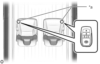
| *a | Inspection Point |
Check the No. 1 indoor electrical key antenna assembly (center rear floor).
When the electrical key transmitter sub-assembly is at either inspection point, check that the buzzer sounds.
- HINT:
- ·
Select either channel 1 or channel 2 and perform the key diagnostic mode inspection for each channel.
·If the buzzer sounds with [CH1] displayed but not with [CH2], the electrical key transmitter sub-assembly cannot be detected by channel 2 due to a malfunction, such as wave interference.
·It is possible to check which No. 1 indoor electrical key antenna assembly (center rear floor) is operating by the sounding of the buzzer.
·When the buzzer does not sound for No. 1 indoor electrical key antenna assembly (center rear floor), it can be judged that the certification ECU (smart key ECU assembly), which controls the No. 1 indoor electrical key antenna assembly (center rear floor), is malfunctioning.
- Body Electrical > Entry&Start > Utility
-
Tester Display Communication Check(Key Diag Mode) - 50005 125 143
- Result:
Result Proceed to The buzzer sounds A The buzzer does not sound B
A
B
Disconnect the N155 certification ECU (smart key ECU assembly) connector.
Disconnect the W25 No. 1 indoor electrical key antenna assembly (center rear floor) connector.
Measure the resistance according to the value(s) in the table below.
- Standard Resistance:
Tester Connection Condition Specified Condition N155-11 (CLG7) - W25-1 (ANTE7) Always Below 1 Ω N155-10 (CG7B) - W25-2 (CLGB) Always Below 1 Ω N155-11 (CLG7) or W25-1 (ANTE7) - Other terminals and body ground Always 10 kΩ or higher N155-10 (CG7B) or W25-2 (CLGB) - Other terminals and body ground Always 10 kΩ or higher
Reconnect the N155 certification ECU (smart key ECU assembly) connector.
- Result:
Proceed to OK NG
OK
NG
Using an oscilloscope, check the waveform.
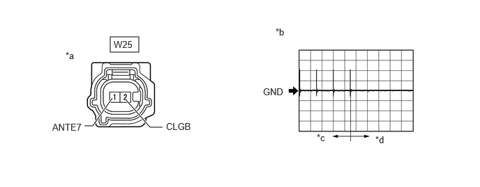
| *a | Front view of wire harness connector
(to No. 1 Indoor Electrical Key Antenna Assembly (Center Rear Floor)) |
*b | Waveform |
| *c | For 30 seconds after closing any door | *d | After 30 seconds or more have elapsed since any door closed |
- OK:
Tester Connection Condition Tool Setting Specified Condition W25-1 (ANTE7) - W25-2 (CLGB) Procedure:
1.Engine switch off
2.Electrical key transmitter sub-assembly not inside vehicle
3.Within 30 seconds of closing any door
2 V/DIV., 500 ms./DIV. Pulse generation
(See waveform)
- Result:
Proceed to OK NG
OK
NG
Install the transmitter battery to the electrical key transmitter sub-assembly.
Bring the electrical key transmitter sub-assembly near the No. 1 indoor electrical key antenna assembly (rear RH floor) and perform an entry and start system check.
- NOTICE:
-
Communication may not be possible if the electrical key transmitter sub-assembly is within 0.2 m (0.656 ft.) of the center of the No. 1 indoor electrical key antenna assembly (rear RH floor).
- HINT:
- ·
As the effect of wave interference decreases by moving the electrical key transmitter sub-assembly close to each indoor electrical key antenna assembly, it may be possible to check whether wave interference is the cause of the problem.
·If the inspection result is that the problem only occurs in certain locations or at certain times of day, the possibility of wave interference is high. Also, added vehicle components may cause wave interference. If installed, remove them and perform the operation check.
·There may be wave interference if the vehicle is near broadcasting antennas, large video displays, wireless garage door opener systems, wireless security cameras, home security systems, etc. In this case, move the vehicle to a different location and check if there is any improvement.
- OK:
The engine starts when the electrical key transmitter sub-assembly is held near each indoor electrical key antenna assembly and the engine switch is pressed with the brake pedal depressed.
- Result:
Proceed to OK NG
OK
NG
Connect the GTS to the DLC3.
Turn the engine switch on (IG).
Turn the GTS on.
Enter the following menus: Body Electrical / Entry&Start / Utility / Communication Check(Key Diag Mode).
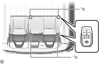
| *a | Inspection Point |
Check the No. 1 indoor electrical key antenna assembly (rear RH floor).
When the electrical key transmitter sub-assembly is at either inspection point, check that the buzzer sounds.
- HINT:
- ·
Select either channel 1 or channel 2 and perform the key diagnostic mode inspection for each channel.
·If the buzzer sounds with [CH1] displayed but not with [CH2], the electrical key transmitter sub-assembly cannot be detected by channel 2 due to a malfunction, such as wave interference.
·It is possible to check which No. 1 indoor electrical key antenna assembly (rear RH floor) is operating by the sounding of the buzzer.
·When the buzzer does not sound for No. 1 indoor electrical key antenna assembly (rear RH floor), it can be judged that the certification ECU (smart key ECU assembly), which controls the No. 1 indoor electrical key antenna assembly (rear RH floor), is malfunctioning.
- Body Electrical > Entry&Start > Utility
-
Tester Display Communication Check(Key Diag Mode) - 50005 125 143
- Result:
Result Proceed to The buzzer sounds A The buzzer does not sound B
A
B
Disconnect the N155 certification ECU (smart key ECU assembly) connector.
Disconnect the W26 No. 1 indoor electrical key antenna assembly (rear RH floor) connector.
Measure the resistance according to the value(s) in the table below.
- Standard Resistance:
Tester Connection Condition Specified Condition N155-13 (CLG8) - W26-1 (ANT2) Always Below 1 Ω N155-12 (CG8B) - W26-2 (ANT1) Always Below 1 Ω N155-13 (CLG8) or W26-1 (ANT2) - Other terminals and body ground Always 10 kΩ or higher N155-12 (CG8B) or W26-2 (ANT1) - Other terminals and body ground Always 10 kΩ or higher
Reconnect the N155 certification ECU (smart key ECU assembly) connector.
- Result:
Proceed to OK NG
OK
NG
Using an oscilloscope, check the waveform.
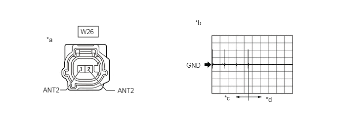
| *a | Front view of wire harness connector
(to No. 1 Indoor Electrical Key Antenna Assembly (rear RH floor)) |
*b | Waveform |
| *c | For 30 seconds after closing any door | *d | After 30 seconds or more have elapsed since any door closed |
- OK:
Tester Connection Condition Tool Setting Specified Condition W26-1 (ANT2) - W26-2 (ANT1) Procedure:
1.Engine switch off
2.Electrical key transmitter sub-assembly not inside vehicle
3.Within 30 seconds of closing any door
2 V/DIV., 500 ms./DIV. Pulse generation
(See waveform)
- Result:
Proceed to OK NG
OK
NG
Install the transmitter battery to the electrical key transmitter sub-assembly.
Bring the electrical key transmitter sub-assembly near the No. 1 indoor electrical key antenna assembly (rear LH floor) and perform an entry and start system check.
- NOTICE:
-
Communication may not be possible if the electrical key transmitter sub-assembly is within 0.2 m (0.656 ft.) of the center of the No. 1 indoor electrical key antenna assembly (rear LH floor).
- HINT:
- ·
As the effect of wave interference decreases by moving the electrical key transmitter sub-assembly close to each indoor electrical key antenna assembly, it may be possible to check whether wave interference is the cause of the problem.
·If the inspection result is that the problem only occurs in certain locations or at certain times of day, the possibility of wave interference is high. Also, added vehicle components may cause wave interference. If installed, remove them and perform the operation check.
·There may be wave interference if the vehicle is near broadcasting antennas, large video displays, wireless garage door opener systems, wireless security cameras, home security systems, etc. In this case, move the vehicle to a different location and check if there is any improvement.
- OK:
The engine starts when the electrical key transmitter sub-assembly is held near each indoor electrical key antenna assembly and the engine switch is pressed with the brake pedal depressed.
- Result:
Proceed to OK NG
OK
NG
Connect the GTS to the DLC3.
Turn the engine switch on (IG).
Turn the GTS on.
Enter the following menus: Body Electrical / Entry&Start / Utility / Communication Check(Key Diag Mode).
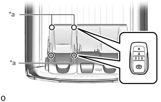
| *a | Inspection Point |
Check the No. 1 indoor electrical key antenna assembly (rear LH floor).
When the electrical key transmitter sub-assembly is at either inspection point, check that the buzzer sounds.
- HINT:
- ·
Select either channel 1 or channel 2 and perform the key diagnostic mode inspection for each channel.
·If the buzzer sounds with [CH1] displayed but not with [CH2], the electrical key transmitter sub-assembly cannot be detected by channel 2 due to a malfunction, such as wave interference.
·It is possible to check which No. 1 indoor electrical key antenna assembly (rear LH floor) is operating by the sounding of the buzzer.
·When the buzzer does not sound for No. 1 indoor electrical key antenna assembly (rear LH floor), it can be judged that the certification ECU (smart key ECU assembly), which controls the No. 1 indoor electrical key antenna assembly (rear LH floor), is malfunctioning.
- Body Electrical > Entry&Start > Utility
-
Tester Display Communication Check(Key Diag Mode) - 50005 125 143
- Result:
Result Proceed to The buzzer sounds A The buzzer does not sound B
A
B
Disconnect the N155 certification ECU (smart key ECU assembly) connector.
Disconnect the V27 No. 1 indoor electrical key antenna assembly (rear LH floor) connector.
Measure the resistance according to the value(s) in the table below.
- Standard Resistance:
Tester Connection Condition Specified Condition N155-4 (CLGP) - V27-1 (ANT2) Always Below 1 Ω N155-3 (CGPB) - V27-2 (ANT1) Always Below 1 Ω N155-4 (CLGP) or V27-1 (ANT2) - Other terminals and body ground Always 10 kΩ or higher N155-3 (CGPB) or V27-2 (ANT1) - Other terminals and body ground Always 10 kΩ or higher
Reconnect the N155 certification ECU (smart key ECU assembly) connector.
- Result:
Proceed to OK NG
OK
NG
Using an oscilloscope, check the waveform.
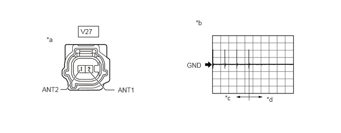
| *a | Front view of wire harness connector
(to No. 1 Indoor Electrical Key Antenna Assembly (rear LH floor)) |
*b | Waveform |
| *c | For 30 seconds after closing any door | *d | After 30 seconds or more have elapsed since any door closed |
- OK:
Tester Connection Condition Tool Setting Specified Condition V27-1 (ANT2) - V27-2 (ANT1) Procedure:
1.Engine switch off
2.Electrical key transmitter sub-assembly not inside vehicle
3.Within 30 seconds of closing any door
2 V/DIV., 500 ms./DIV. Pulse generation
(See waveform)
- Result:
Proceed to OK NG
OK
NG
Check the transmitter battery level of the electrical key transmitter sub-assembly that was checked first.
Press and hold the lock switch of the electrical key transmitter sub-assembly for 5 seconds and check the number of times that the LED illuminates.
- HINT:
- ·
The electrical key transmitter sub-assembly sends voltage information to the certification ECU (smart key ECU assembly) when it is being used. "Yes" is displayed for the Data List item "Key Low Battery" when this voltage information indicates 2.2 V or less.
·Even if the transmitter battery is depleted, it is still possible to start the engine by holding the electrical key transmitter sub-assembly near the engine switch, depressing the brake pedal and pressing the engine switch.
- Result:
Result Proceed to LED illuminates 3 times or more when switch is pressed and held A LED does not illuminate when switch is pressed and held B LED illuminates once or twice but not a third time C
A
B
C
Check that the entry lock and unlock functions operate on each door.
- HINT:
-
If the door control receiver is defective, code verification does not begin in the cabin and the entry lock and unlock functions do not operate.
- Result:
Result Proceed to Entry lock/unlock functions operate normally A Entry lock/unlock functions do not operate normally B
A
B
Connect the GTS to the DLC3.
Turn the engine switch on (IG).
Turn the GTS on.
Enter the following menus: Body Electrical / Power Source Control / Data List.
Read the Data List according to the display on the GTS.
- Body Electrical > Power Source Control > Data List
-
Tester Display Measurement Item Range Normal Condition Diagnostic Note Start Switch1 Engine switch 1 status OFF or ON OFF: Engine switch not pressed
ON: Engine switch pressed·If the engine switch is pressed for a short time, the display may not change.
·Use this item to determine if the engine switch input signal is malfunctioning.
Start Switch2 Engine switch 2 status OFF or ON OFF: Engine switch not pressed
ON: Engine switch pressed·Backup for engine switch 1. However, when the engine switch is pressed and held, the power source mode can only be changed when both engine switch 1 and 2 are normal.
·Behaves the same way as engine switch 1.
- Body Electrical > Power Source Control > Data List
-
Tester Display Start Switch1 Start Switch2 - 50003 223 4,5
- OK:
The GTS display changes correctly in response to the engine switch operation.
- Result:
Proceed to OK NG
OK
NG
Measure the voltage while confirming the power source mode on the Data List.

| *a | Component with harness connected
(Certification ECU (Smart Key ECU Assembly)) |
- | - |
- Body Electrical > Power Source Control > Data List
-
Tester Display Measurement Item Range Normal Condition Diagnostic Note Power Supply Condition Power supply state All OFF, ACC ON, IG ON or ST ON All OFF: Engine switch off
ACC ON: Engine switch on (ACC)
IG ON: Engine switch on (IG)
ST ON: Sending engine start request signal-
- Body Electrical > Power Source Control > Data List
-
Tester Display Power Supply Condition - 50003 223 18
- Standard Voltage:
Tester Connection Switch Condition Specified Condition N156-17 (IG1D) - Body ground Engine switch off 1 V or less Engine switch on (ACC) Engine switch on (IG) 9 V or higher N156-16 (ACCD) - Body ground Engine switch off 1 V or less Engine switch on (ACC) 8.5 V or higher Engine switch on (IG)
- Result:
Proceed to OK NG
OK
NG
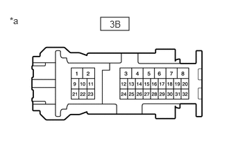
| *a | Front view of wire harness connector
(to Instrument Panel Junction Block Assembly) |
Disconnect the instrument panel junction block assembly connector.
Measure the resistance according to the value(s) in the table below.
- Standard Resistance:
Tester Connection Condition Specified Condition 3B-3 - Body ground Always Below 1 Ω
- Result:
Proceed to OK NG
OK
for LHD:
for RHD:
NG
Remove the engine switch.
for 7GR-FKS:
for 1GD-FTV:
Inspect the engine switch.
for 7GR-FKS:
for 1GD-FTV:
- Result:
Proceed to OK NG
OK
NG
for 7GR-FKS:
for 1GD-FTV:
Disconnect the N156 certification ECU (smart key ECU assembly) connector.
Measure the resistance according to the value(s) in the table below.
- Standard Resistance:
Tester Connection Condition Specified Condition N156-23 (SSW1) - N162-5 (SS1) Always Below 1 Ω N156-21 (SSW2) - N162-1 (SS2) Always Below 1 Ω N156-11 (AGND) - N162-6 (AGND) Always Below 1 Ω N156-23 (SSW1) or N162-5 (SS1) - Other terminals and body ground Always 10 kΩ or higher N156-21 (SSW2) or N162-1 (SS2) - Other terminals and body ground Always 10 kΩ or higher N156-11 (AGND) or N162-6 (AGND) - Other terminals and body ground Always 10 kΩ or higher
- Result:
Proceed to OK NG
OK
NG
Inspect the transmitter battery.
- NOTICE:
-
Do not wrap the lead wire around a terminal, wedge it between terminals, or solder it. The terminal may be deformed or damaged, and the transmitter battery will not be able to be installed correctly.
- Result:
Proceed to OK NG
OK
NG