POWER DISTRIBUTION MAIN BODY ECU(for LHD) REMOVAL
CAUTION / NOTICE / HINT
The necessary procedures (adjustment, calibration, initialization, or registration) that must be performed after parts are removed, installed, or replaced during the main body ECU (multiplex network body ECU) removal/installation are shown below.
| Replaced Part or Performed Procedure | Necessary procedures | Effect/Inoperative Function When Necessary Procedures are not Performed | Link |
|---|---|---|---|
| Disconnect cable from negative (-) battery terminal | Memorize steering angle neutral point | Parking assist monitor system | ( 201902,999999,_56,_079315,_0385736,RM100000001GNRA,) 201902,999999,_56,_079315,_0385736,RM100000001GNRA,)
|
| Panoramic view monitor system | (201902,999999,_56,_079315,_0385736,RM100000001GNRA,)
|
||
w/ Entry and Start System:
Replacement of main body ECU (multiplex network body ECU) |
Code registration | ·
Wireless door lock control system (w/ Entry and Start System) ·
Entry and start system (for Entry function) ·
Entry and start system (for Start function) ·
Engine start function |
See Service Bulletin for the registration method. |
- HINT:
-
When the cable is disconnected / reconnected to the battery terminal, systems temporarily stop operating. However, each system has a function that completes learning the first time the system is used.
- ·
Learning completes when vehicle is driven
Effect/Inoperative Function When Necessary Procedures are not Performed Necessary Procedures Link Lane control system Drive the vehicle straight ahead at 15 km/h (10 mph) or more for 1 second or more. ( 201902,999999,_58,_078886,_0382740,RM100000001G6XB,)
Pre-collision system
·Learning completes when vehicle is operated normally
Effect/Inoperative Function When Necessary Procedures are not Performed Necessary Procedures Link Power slide door system Fully close the slide door by hand.
- HINT:
-
Initialization is not necessary if the above procedures are performed while the slide door is closed.
( 201902,999999,_59,_078503,_0381017,RM100000001FWXM,)
Air conditioning system After the ignition switch is turned to ON, the servo motor standard position is recognized. -
PROCEDURE

 1. PRECAUTION
- CAUTION:
-
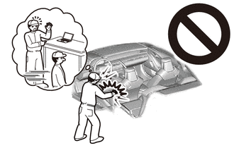
-
Be sure to read Precaution thoroughly before servicing.
- ·
- NOTICE:
- ·
After turning the ignition switch off, waiting time may be required before disconnecting the cable from the negative (-) battery terminal.
·Do not remove the main body ECU (multiplex network body ECU) except when replacing it.
·When removing the main body ECU (multiplex network body ECU), always replace it with a new one.
2.DISCONNECT CABLE FROM NEGATIVE BATTERY TERMINAL
- CAUTION:
-
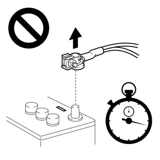
- ·
Wait at least 90 seconds after disconnecting the cable from the negative (-) battery terminal to disable the SRS system.
·If the airbag deploys for any reason, it may cause a serious accident.
67912A
3.REMOVE FRONT DOOR OUTSIDE SCUFF PLATE LH
67914B
4.REMOVE FRONT DOOR SCUFF PLATE LH
62112
5.REMOVE COWL SIDE TRIM BOARD LH
55631A
6.REMOVE NO. 1 INSTRUMENT PANEL UNDER TRAY STOPPER
55011A
7.REMOVE NO. 1 INSTRUMENT PANEL GARNISH SUB-ASSEMBLY
55318C
8.REMOVE INSTRUMENT SIDE PANEL LH
55641
9.REMOVE NO. 1 INSTRUMENT PANEL UNDER COVER
53601
10.REMOVE HOOD LOCK CONTROL LEVER SUB-ASSEMBLY
77306
11.REMOVE FUEL LID LOCK OPEN LEVER SUB-ASSEMBLY
55432D
12.REMOVE LOWER NO. 1 INSTRUMENT PANEL FINISH PANEL
55044C
13.REMOVE INSTRUMENT PANEL FINISH PANEL SUB-ASSEMBLY
55433B
14.REMOVE LOWER NO. 2 INSTRUMENT PANEL FINISH PANEL
55445B
15.REMOVE INSTRUMENT PANEL FINISH PLATE (w/o Knee Airbag)
55313
16.REMOVE LOWER INSTRUMENT PANEL LH (w/o Knee Airbag)
73900
17.REMOVE LOWER NO. 1 INSTRUMENT PANEL AIRBAG ASSEMBLY (w/ Knee Airbag)
18.REMOVE INSTRUMENT PANEL JUNCTION BLOCK ASSEMBLY WITH MAIN BODY ECU (for Manual Transmission)
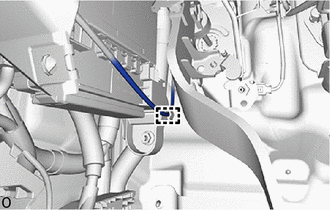
Detach the hood look control cable assembly from the guide.
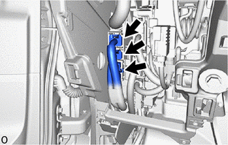
Disconnect the 3 connectors.

|
Rotate in this Direction |
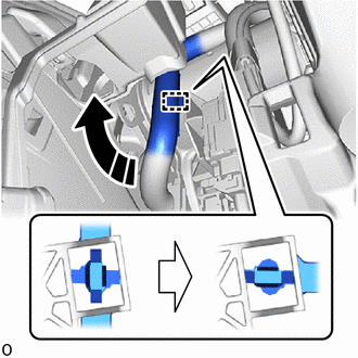
Rotate the wire harness clockwise and detach the wire harness clamp as shown in the illustration.
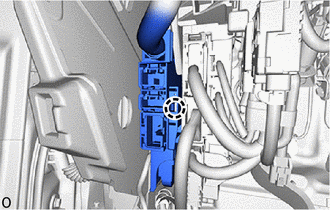
Detach the claw and remove the connector holder from the instrument panel junction block assembly with main body ECU.
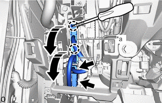
| *a | Lever Connector |
|
|
Rotate in this Direction |

|
Protective Tape |
Using a thin-bladed screwdriver with its tip wrapped with protective tape, detach the claw and disconnect the 2 lever connectors.
Disconnect the 2 connectors.
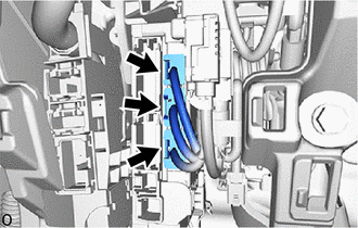
Disconnect the 3 connectors.
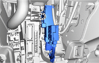
Detach the claw and remove the wiring harness protector from the instrument panel junction block assembly with main body ECU.
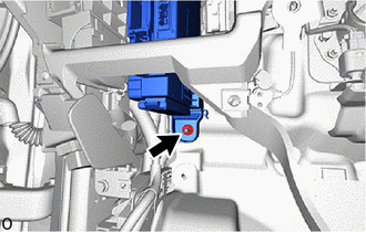
Remove the nut.
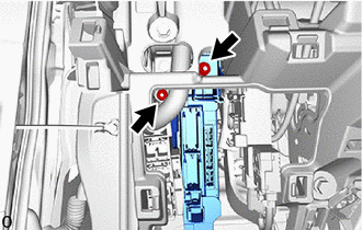
Remove the 2 nuts and disconnect the instrument panel junction block assembly with main body ECU together with the wiring harness clamp bracket.
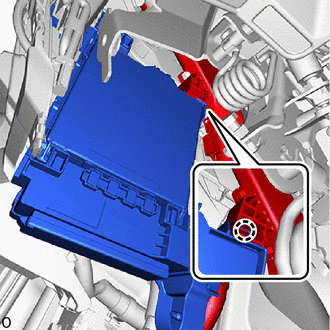
Detach the claw and remove the wiring harness protector assembly from the instrument panel junction block assembly with main body ECU.
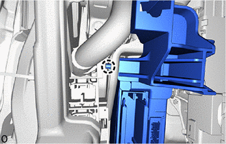
Detach the claw and remove the instrument panel junction block assembly with main body ECU from the wiring harness clamp bracket.
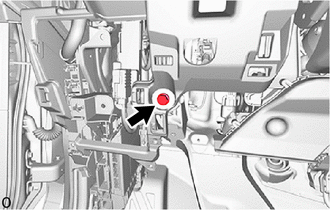
Remove the bolt.
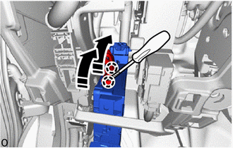
|
|
Rotate in this Direction |
|
|
Protective Tape |
Using a thin-bladed screwdriver with its tip wrapped with protective tape, detach the claw, disconnect the 2 lever connectors and remove the instrument panel junction block assembly with main body ECU.
19.REMOVE INSTRUMENT PANEL JUNCTION BLOCK ASSEMBLY WITH MAIN BODY ECU (for Automatic Transmission)
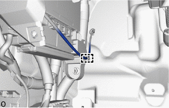
Detach the hood look control cable assembly from the guide.
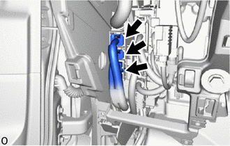
Disconnect the 3 connectors.
|
|
Rotate in this Direction |
Rotate the wire harness clockwise and detach the wire harness clamp as shown in the illustration.
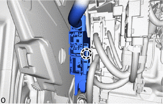
Detach the claw and remove the connector holder from the instrument panel junction block assembly with main body ECU.
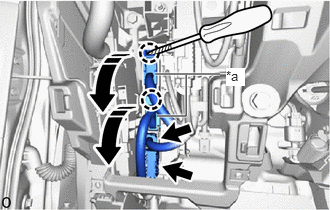
| *a | Lever Connector |
|
|
Rotate in this Direction |
|
|
Protective Tape |
Using a thin-bladed screwdriver with its tip wrapped with protective tape, detach the claw and disconnect the 2 lever connectors.
Disconnect the 2 connectors.
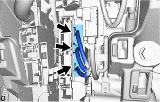
Disconnect the 3 connectors.
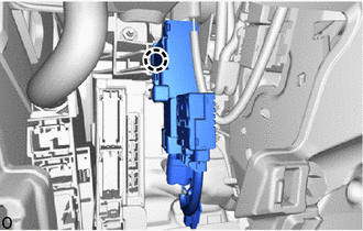
Detach the claw and remove the wiring harness protector from the instrument panel junction block assembly with main body ECU.
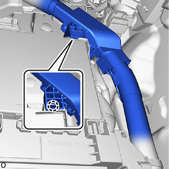
Detach the claw and remove the wiring harness protector from the instrument panel junction block assembly with main body ECU.
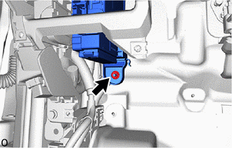
Remove the nut.
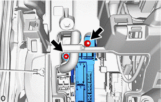
Remove the 2 nuts and disconnect the instrument panel junction block assembly with main body ECU together with the wiring harness clamp bracket.
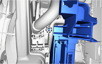
Detach the claw and remove the instrument panel junction block assembly with main body ECU from the wiring harness clamp bracket.
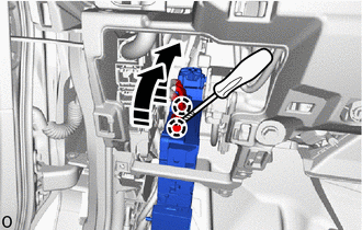
|
|
Rotate in this Direction |
|
|
Protective Tape |
Using a thin-bladed screwdriver with its tip wrapped with protective tape, detach the claw and disconnect the 2 lever connectors and remove the instrument panel junction block assembly with main body ECU.
20.REMOVE MAIN BODY ECU (MULTIPLEX NETWORK BODY ECU)
Press the lock of the instrument panel junction block assembly and release the lock of the main body ECU (multiplex network body ECU) as shown in the illustration.
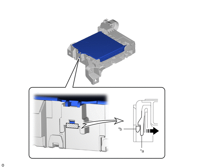
| *a | Instrument Panel Junction Block Assembly | *b | Main Body ECU (Multiplex Network Body ECU) |
|
|
Movement Direction |
|
Instrument Panel Junction Block Assembly Lock |
While pressing the lock, horizontally insert a thin-bladed screwdriver with its tip wrapped with protective tape between the main body ECU (multiplex network body ECU) and instrument panel junction block assembly.
- NOTICE:
-
Use a screwdriver with a diameter between 5.0 mm (0.197 in.) and 6.3 mm (0.248 in.) and a length of approximately 90 mm (3.54 in.).
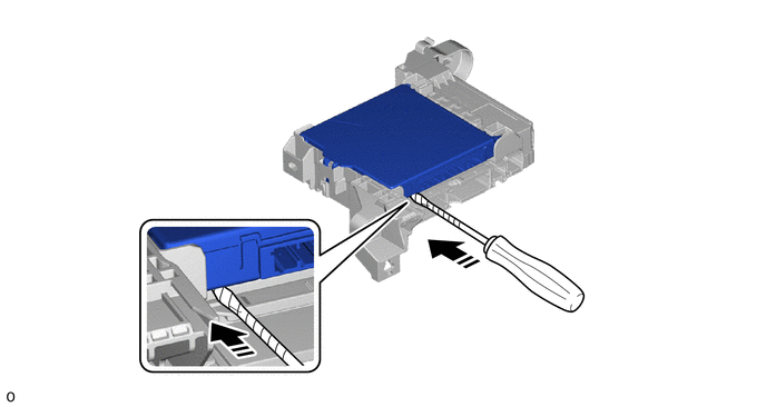
|
|
Horizontally Insert a Thin-bladed Screwdriver |
|
Protective Tape |
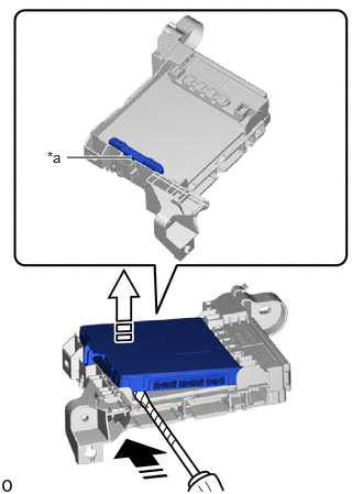
| *a | Internal Connector |
|
|
Insert a Thin-bladed Screwdriver in this Direction |

|
Released in this Direction |
|
|
Protective Tape |
When the thin-bladed screwdriver with its tip wrapped with protective tape is inserted, the internal connector lock is released.
- NOTICE:
- ·
Do not twist the screwdriver to raise the main body ECU (multiplex network body ECU).
·Do not excessively insert the screwdriver. Otherwise, the internal connector terminals may become deformed or damaged.
·Replace the instrument panel junction block assembly when the connector terminal, the locking section, or the case is damaged or deformed.
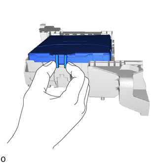
Hold the rib of the main body ECU (multiplex network body ECU).
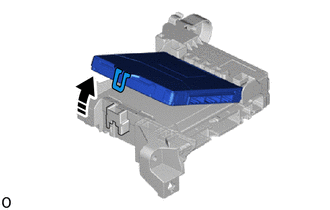
|
|
Rotate in this Direction |
While rotating the main body ECU (multiplex network body ECU), completely release the lock.
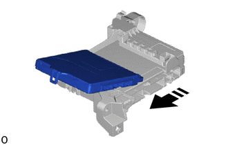
|
|
Remove in this Direction |
Remove the main body ECU (multiplex network body ECU) from the instrument panel junction block assembly.