THEFT DETERRENT / KEYLESS ENTRY ENTRY AND START SYSTEM(for Start Function) OPERATION CHECK
CHECK CUSTOMIZE PARAMETERS
- NOTICE:
-
The operation check below is based on the non-customized initial condition of the vehicle.
CHECK PUSH-BUTTON START FUNCTION
Get into the vehicle while carrying the electrical key transmitter sub-assembly with the engine switch off. With the shift state park (P), check that the key indicator display is displayed when the brake pedal is depressed. Check that the engine starts when the engine switch is pressed after the key indicator display is displayed in the combination meter assembly.
While carrying the electrical key transmitter sub-assembly, check that the power source mode changes in the following order when the engine switch is pressed with the brake pedal released: off → on (ACC) → on (IG) → off.
With the shift state park (P), check that the steering lock operates when a door is opened.
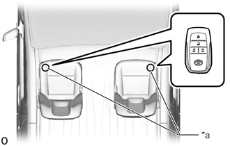
| *a | Inspection Point |
Check the push-button start function operation range for the front side. Place the electrical key transmitter sub-assembly at either inspection point so that it is facing the direction shown in the illustration, and then check that the engine can be started.
- NOTICE:
-
Even if the electrical key transmitter sub-assembly is in a vehicle interior detection area, it may not be properly detected if it is on the instrument panel, in the glove box, in the door pocket, in the console or on the floor.
- HINT:
- ·
Communication may not be possible if the electrical key transmitter sub-assembly is within 0.2 m (0.656 ft.) of the No. 1 indoor electrical key antenna assembly (front floor).
·Perform this inspection for both inspection points.
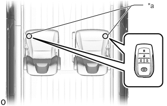
| *a | Inspection Point |
Check the push-button start function operation range for the center front side. Place the electrical key transmitter sub-assembly at either inspection point so that it is facing the direction shown in the illustration, and then check that the engine can be started.
- NOTICE:
-
Even if the electrical key transmitter sub-assembly is in a vehicle interior detection area, it may not be properly detected if it is on the instrument panel, in the glove box, in the door pocket, in the console or on the floor.
- HINT:
- ·
Communication may not be possible if the electrical key transmitter sub-assembly is within 0.2 m (0.656 ft.) of the center of the No. 1 indoor electrical key antenna assembly (center front floor).
·Perform this inspection for both inspection points.
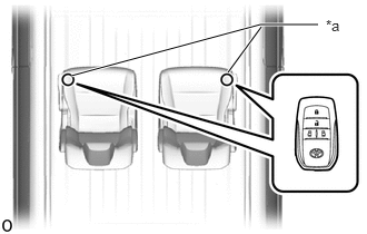
| *a | Inspection Point |
Check the push-button start function operation range for the center rear side. Place the electrical key transmitter sub-assembly at either inspection point so that it is facing the direction shown in the illustration, and then check that the engine can be started.
- NOTICE:
- ·
Even if the electrical key transmitter sub-assembly is within the vehicle interior detection area, the electrical key transmitter sub-assembly may not be properly detected if it is on the instrument panel, in the glove box or on the floor.
·for RHD with Wirless Door Lock Buzzer Answer-back Function:
Engine does not start with back door opened.
- HINT:
- ·
Communication may not be possible if the electrical key transmitter sub-assembly is within 0.2 m (0.656 ft.) of the No. 1 indoor electrical key antenna assembly (center rear floor).
·Perform the inspection for both inspection points.
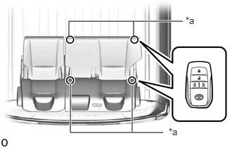
| *a | Inspection Point |
Check the push-button start function operation range for the rear RH side. Place the electrical key transmitter sub-assembly at either inspection point so that it is facing the direction shown in the illustration, and then check that the engine can be started.
- NOTICE:
-
Even if the electrical key transmitter sub-assembly is in a vehicle interior detection area, it may not be properly detected if it is on the instrument panel, in the glove box, in the door pocket, in the console or on the floor.
- HINT:
- ·
Communication may not be possible if the electrical key transmitter sub-assembly is within 0.2 m (0.656 ft.) of the No. 1 indoor electrical key antenna assembly (rear RH floor).
·Perform the inspection for both inspection points.
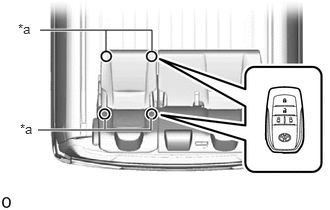
| *a | Inspection Point |
Check the push-button start function operation range for the rear LH side. Place the electrical key transmitter sub-assembly at either inspection point so that it is facing the direction shown in the illustration, and then check that the engine can be started.
- NOTICE:
-
Even if the electrical key transmitter sub-assembly is in a vehicle interior detection area, it may not be properly detected if it is on the instrument panel, in the glove box, in the door pocket, in the console or on the floor.
- HINT:
- ·
Communication may not be possible if the electrical key transmitter sub-assembly is within 0.2 m (0.656 ft.) of the No. 1 indoor electrical key antenna assembly (rear LH floor).
·Perform the inspection for both inspection points.
CHECK POWER SOURCE MODE CHANGING FUNCTION
Check that the power source mode changes according to the chart below.
| Shift Position | Brake Pedal | Power Source Mode when Engine Switch Pressed |
|---|---|---|
| Park (P) selected | Released | Off → on (ACC) → on (IG) → off |
| Park (P) selected | Depressed | Off → engine starts |
| Park (P) selected | Depressed | On (ACC) → engine starts |
| Park (P) selected | Depressed | On (IG) → engine starts |
| Park (P) selected | Released / Depressed | Engine running → off |
| Park (N) selected | Released | Off → on (ACC) → on (IG) → on (ACC) |
| Park (N) selected | Depressed | Off → engine starts |
| Park (N) selected | Depressed | On (ACC) → engine starts |
| Park (N) selected | Depressed | On (IG) → engine starts |
| Park (N) selected | Released / Depressed | Engine running → on (ACC) |
| Park (P) or (N) not selected | Released | On (ACC) → on (IG) → on (ACC) |
| Park (P) or (N) not selected | Depressed | Off → on (IG) |
| Park (P) or (N) not selected | Depressed | On (ACC) → on (IG) |
| Park (P) or (N) not selected | Released / Depressed | Engine running → on (ACC) |
CHECK TRANSMITTER BATTERY SAVING MODE FUNCTION
Press the unlock switch of the electrical key transmitter sub-assembly twice while pressing the lock switch and check that the electrical key transmitter sub-assembly LED blinks 4 times and enters transmitter battery saving mode.
Check that the entry and start system does not operate while in transmitter battery saving mode.
- HINT:
-
To cancel transmitter battery saving mode, press a switch of the electrical key transmitter sub-assembly.
CHECK ENTRY CANCEL FUNCTION
Cancel the entry and start system and check that all the functions of the entry and start system no longer operate.
- HINT:
-
While the entry and start system is canceled, it is possible to lock and unlock the doors with the wireless function, and the engine can be started by holding the electrical key transmitter sub-assembly near the engine switch.
CHECK KEY DIAGNOSTIC MODE