THEFT DETERRENT / KEYLESS ENTRY ELECTRICAL KEY OSCILLATOR(for Instrument Panel Side) REMOVAL
CAUTION / NOTICE / HINT
The necessary procedures (adjustment, calibration, initialization or registration) that must be performed after parts are removed, installed or replaced during the No. 1 indoor electrical key antenna assembly removal/installation are shown below.
| Replacement Part or Procedure | Necessary Procedures | Effect/Inoperative Function When Necessary Procedures are not Performed | Link |
|---|---|---|---|
| Disconnect cable from negative (-) battery terminal | Memorize steering angle neutral point | Parking assist monitor system | ( 201902,999999,_56,_079315,_0385736,RM100000001GNRA,) 201902,999999,_56,_079315,_0385736,RM100000001GNRA,)
|
| Panoramic view monitor system | (201906,999999,_56,_079315,_0396274,RM100000001IGR3,)
|
- CAUTION:
- ·
Wear protective gloves. Sharp areas on the parts may injure your hands.
·There is risk of injury.
- HINT:
- ·
When the cable is disconnected/reconnected to the battery terminal, systems temporarily stop operating. However, each system has a function that completes learning the first time the systems is used.
-Learning completes when vehicle is driven
Effect/Inoperative Function When Necessary Procedures are not Performed Necessary Procedures Link *: w/ Stop and start system
Stop and start system* Drive the vehicle until stop and start control is permitted (approximately 5 to 60 minutes). ( 201902,999999,_51,_078825,_0382334,RM100000001GBQ1,)
Lane control system Drive the vehicle straight ahead at 15 km/h (10 mph) or more for 1 second or more. ( 201902,999999,_58,_078886,_0382740,RM100000001G6XB,)
Pre-collision system
-Learning completes when vehicle is operated normally
Effect/Inoperative Function When Necessary Procedures are not Performed Necessary Procedures Link Power slide door system Fully close the slide door by hand.
- HINT:
-
Initialization is not necessary if the above procedures are performed while the slide door is closed.
( 201902,999999,_59,_078503,_0381017,RM100000001FWXM,)
Air conditioning system After the ignition switch is turned to ON, the servo motor standard position is recognized. -
·Use the same procedure for RHD and LHD vehicles.
·The procedure listed below is for LHD vehicles.
·The procedure listed below is a representative example.
PROCEDURE

 1. PRECAUTION
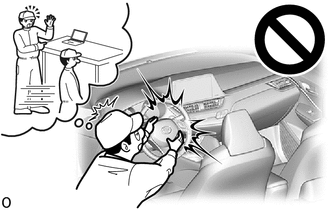
- CAUTION:
-
-
Be sure to read Precaution thoroughly before servicing.
- ·
- NOTICE:
- ·
After turning the ignition switch off, waiting time may be required before disconnecting the cable from the negative (-) battery terminal.
·If the front seat airbag assembly was deployed, replace the front seat airbag assembly, front seatback frame sub-assembly, separate type front seatback pad and separate type front seatback cover with the necessary parts in accordance with the extent of the collision damage.
·Replace any other damaged parts as necessary.
2.REMOVE FRONT SEAT ASSEMBLY LH
for Separate Seat Type:
for Sliding Bench Seat Type:
3.REMOVE FRONT SEAT ASSEMBLY RH
- HINT:
-
Use the same procedure described for the LH side.
4.REMOVE CONSOLE BOX ASSEMBLY (w/ Console Box)
86183E
5.REMOVE AUDIO AMPLIFIER COVER (for 12 Speakers)
6.REMOVE STEREO COMPONENT AMPLIFIER ASSEMBLY WITH BRACKET (for 12 Speakers)
67912A
7.REMOVE FRONT DOOR OUTSIDE SCUFF PLATE LH
67914B
8.REMOVE FRONT DOOR SCUFF PLATE LH
67911B
9.REMOVE FRONT DOOR OUTSIDE SCUFF PLATE RH
- HINT:
-
Use the same procedure described for the LH side.
67913B
10.REMOVE FRONT DOOR SCUFF PLATE RH
- HINT:
-
Use the same procedure described for the LH side.
62112
11.REMOVE COWL SIDE TRIM BOARD LH
62111C
12.REMOVE COWL SIDE TRIM BOARD RH
73233
13.REMOVE OUTER LAP BELT ANCHOR COVER
73220
14.REMOVE FRONT SEAT OUTER BELT ASSEMBLY LH (FLOOR ANCHOR)
73210
15.REMOVE FRONT SEAT OUTER BELT ASSEMBLY RH (FLOOR ANCHOR)
- HINT:
-
Use the same procedure described for the LH side.
67917C
16.REMOVE REAR DOOR SCUFF PLATE RH
67918D
17.REMOVE REAR DOOR SCUFF PLATE LH
- HINT:
-
Use the same procedure described for the RH side.
74617A
18.REMOVE ASSIST GRIP PLUG
- HINT:
-
Use the same procedure for both assist grip plugs.
74680
19.REMOVE PILLAR ASSIST GRIP ASSEMBLY B
- HINT:
-
Use the same procedure for both pillar assist grip assembly B.
62312B
20.REMOVE FRONT DOOR OPENING TRIM WEATHERSTRIP LH
- HINT:
-
Pull back the front door opening trim weatherstrip RH so that the lower center pillar garnish LH can be removed.
62311B
21.REMOVE FRONT DOOR OPENING TRIM WEATHERSTRIP RH
- HINT:
-
Use the same procedure described for the LH side.
67871E
22.REMOVE NO. 1 SLIDE DOOR WEATHERSTRIP RH
- HINT:
-
Pull back the No. 1 slide door weatherstrip RH so that the lower center pillar garnish RH can be removed.
67872A
23.REMOVE NO. 1 SLIDE DOOR WEATHERSTRIP LH
- HINT:
- ·
Pull back the No. 1 slide door weatherstrip LH so that the lower center pillar garnish LH can be removed.
·Use the same procedure described for the RH side.
62413A
24.REMOVE LOWER CENTER PILLAR GARNISH RH
62414A
25.REMOVE LOWER CENTER PILLAR GARNISH LH
- HINT:
-
Use the same procedure described for the RH side.
55641
26.REMOVE NO. 1 INSTRUMENT PANEL UNDER COVER
55642
27.REMOVE NO. 2 INSTRUMENT PANEL UNDER COVER
58534E
28.REMOVE CENTER FLOOR CARPET COVER LH
58533C
29.REMOVE CENTER FLOOR CARPET COVER RH
55646
30.REMOVE NO. 3 INSTRUMENT PANEL UNDER COVER
87212G
31.REMOVE REAR NO. 3 AIR DUCT (w/ Rear Foot Duct)
87212F
32.REMOVE REAR NO. 2 AIR DUCT (w/ Rear Foot Duct)
58510D
33.REMOVE FRONT FLOOR CARPET ASSEMBLY
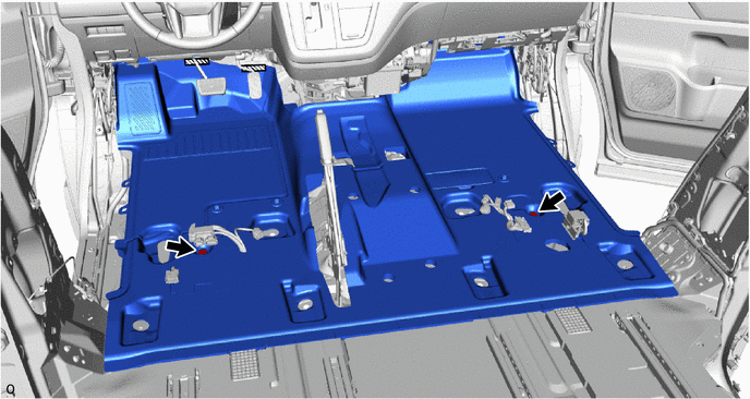
for LHD:
Using a clip remover, remove the 2 clips.
Detach each fastener and remove the front floor carpet assembly.

|
Fastener | - | - |
for RHD:
Using a clip remover, remove the 2 clips.
Detach each fastener and remove the front floor carpet assembly.

|
|
Fastener | - | - |
899A0
34.REMOVE NO. 1 INDOOR ELECTRICAL KEY ANTENNA ASSEMBLY
- NOTICE:
-
Do not reuse parts if dropped or subjected to any strong impact.
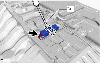
| *a | Protective Tape |
Using a thin-bladed screwdriver, detach the claw and remove the No. 1 indoor electrical key antenna assembly.
- HINT:
-
Tape the thin-bladed screwdriver tip before use.
Disconnect the connector.