RM35X0E
_51
Engine / Hybrid System
_078665
7GR-FKS STARTING
_0398551
ENGINE SWITCH
G
7GR-FKS STARTING ENGINE SWITCH INSPECTION
PROCEDURE

 1.INSPECT ENGINE SWITCH
a.
Check the resistance.
i.
0.76,0.906 1.208,1.073
true
2.208,1.083 2.688,0.927
true
2.219,1.344 2.698,1.573
true
1.146,1.906 1.521,1.427
true
0.052,0.042 0.365,0.198
0.313,0.156
10
*a
0.458,0.823 0.917,1.021
0.458,0.198
10
SS1
2.75,0.854 3.208,1.052
0.458,0.198
10
SS2
2.781,1.531 3.396,1.729
0.615,0.198
10
AGND
0.938,1.927 1.365,2.125
0.427,0.198
10
SWIL
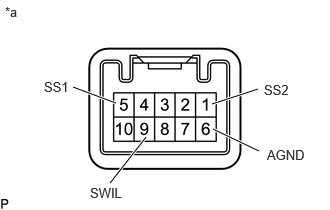
| *a | Component without harness connected
(Engine Switch) |
Measure the resistance according to the value(s) in the table below.
- Standard Resistance:
Tester Connection Condition Specified Condition 5 (SS1) - 6 (AGND)
1 (SS2) - 6 (AGND)Not pushed 10 kΩ or higher Pushed Below 1 Ω
If the result is not as specified, replace the engine switch.
b.
Check the LED illumination.
i.
Apply battery voltage between the terminals of the engine switch and check the illumination condition of the engine switch indicator light.
- OK:
Condition Specified Condition Battery positive (+) → Terminal 9 (SWIL)
Battery negative (-) → Terminal 6 (AGND)Illuminates
- HINT:
- ·
If the positive (+) lead and the negative (-) lead are incorrectly connected, the engine switch indicator light will not illuminate.
·If the voltage is too low, the engine switch indicator light will not illuminate.
If the result is not as specified, replace the engine switch.