M20F-FXS, M20G-FXS ENGINE CONTROL SFI SYSTEM P030000 Random/Multiple Cylinder Misfire Detected P030027 Random/Multiple Cylinder Misfire Detected (Emission) Signal Rate of Change Above Threshold P030085 Random / Multiple Cylinder Misfire Detected (Over Temperature) Signal Above Allowable Range P030100 Cylinder 1 Misfire Detected P030200 Cylinder 2 Misfire Detected P030300 Cylinder 3 Misfire Detected P030400 Cylinder 4 Misfire Detected
DESCRIPTION
When the engine misfires, high concentrations of hydrocarbons (HC) enter the exhaust gas. Extremely high hydrocarbon concentration levels can cause an increase in exhaust emission levels. Extremely high concentrations of hydrocarbons can also cause increases in the three-way catalytic converter temperature, which may cause damage to the three-way catalytic converter. To prevent this increase in emissions and to limit the possibility of thermal damage, the ECM monitors the misfire count. When the temperature of the three-way catalytic converter reaches the point of thermal degradation, the ECM blinks the MIL. To monitor misfires, the ECM uses both the camshaft position sensor and the crankshaft position sensor. The camshaft position sensor is used to identify any misfiring cylinders and the crankshaft position sensor is used to measure variations in the crankshaft rotation speed. Misfires are counted when the crankshaft rotation speed variations exceed predetermined thresholds. If the misfire count exceeds the threshold levels, and could cause emission control system performance deterioration, the ECM illuminates the MIL and stores a DTC.
| DTC No. | Detection Item | DTC Detection Condition | Trouble Area | MIL | Note |
|---|---|---|---|---|---|
| P030000 | Random/Multiple Cylinder Misfire Detected | Simultaneous misfiring of several cylinders occurs and one of the following conditions is met (2 trip detection logic):
·
A misfire occurs that may damage the three-way catalytic converter (MIL blinks immediately when detected). ·
An emission deterioration misfire occurs (MIL illuminates). |
·
Open or short in engine wire harness ·
Connector connection ·
Vacuum hose connections ·
Ignition system ·
Port fuel injector assembly ·
Direct fuel injector assembly ·
Fuel pressure ·
Mass air flow meter ·
Engine coolant temperature sensor ·
Compression pressure ·
Valve timing ·
PCV valve and hose ·
PCV hose connections ·
Intake system ·
EGR valve assembly ·
ECM |
Comes on/Blinks*
*: The MIL flashes when a catalyst-damaging misfire is detected. |
SAE Code: P0300 |
| P030027 | Random/Multiple Cylinder Misfire Detected (Emission) Signal Rate of Change Above Threshold | An emission deterioration misfire occurs (2 trip detection logic). | ·
Open or short in engine wire harness ·
Connector connection ·
Vacuum hose connections ·
Ignition system ·
Port fuel injector assembly ·
Direct fuel injector assembly ·
Fuel pressure ·
Mass air flow meter ·
Engine coolant temperature sensor ·
Compression pressure ·
Valve timing ·
PCV valve and hose ·
PCV hose connections ·
Intake system ·
EGR valve assembly ·
ECM |
Comes on | SAE Code: - |
| P030085 | Random / Multiple Cylinder Misfire Detected (Over Temperature) Signal Above Allowable Range | A misfire occurs that may damage the three-way catalytic converter (2 trip detection logic). | ·
Open or short in engine wire harness ·
Connector connection ·
Vacuum hose connections ·
Ignition system ·
Port fuel injector assembly ·
Direct fuel injector assembly ·
Fuel pressure ·
Mass air flow meter ·
Engine coolant temperature sensor ·
Compression pressure ·
Valve timing ·
PCV valve and hose ·
PCV hose connections ·
Intake system ·
EGR valve assembly ·
ECM |
Comes on/Blinks*
*: The MIL flashes when a catalyst-damaging misfire is detected. |
SAE Code: - |
| P030100 | Cylinder 1 Misfire Detected | Misfiring of a specific cylinder occurs and one of the following conditions is met (2 trip detection logic):
·
A misfire occurs that may damage the three-way catalytic converter (MIL blinks immediately when detected). ·
An emission deterioration misfire occurs (MIL illuminates). |
·
Open or short in engine wire harness ·
Connector connection ·
Vacuum hose connections ·
Ignition system ·
Port fuel injector assembly ·
Direct fuel injector assembly ·
Fuel pressure ·
Mass air flow meter ·
Engine coolant temperature sensor ·
Compression pressure ·
Valve timing ·
PCV valve and hose ·
PCV hose connections ·
Intake system ·
EGR valve assembly ·
ECM |
Comes on/Blinks*
*: The MIL flashes when a catalyst-damaging misfire is detected. |
SAE Code: P0301 |
| P030200 | Cylinder 2 Misfire Detected | Misfiring of a specific cylinder occurs and one of the following conditions is met (2 trip detection logic):
·
A misfire occurs that may damage the three-way catalytic converter (MIL blinks immediately when detected). ·
An emission deterioration misfire occurs (MIL illuminates). |
·
Open or short in engine wire harness ·
Connector connection ·
Vacuum hose connections ·
Ignition system ·
Port fuel injector assembly ·
Direct fuel injector assembly ·
Fuel pressure ·
Mass air flow meter ·
Engine coolant temperature sensor ·
Compression pressure ·
Valve timing ·
PCV valve and hose ·
PCV hose connections ·
Intake system ·
EGR valve assembly ·
ECM |
Comes on/Blinks*
*: The MIL flashes when a catalyst-damaging misfire is detected. |
SAE Code: P0302 |
| P030300 | Cylinder 3 Misfire Detected | Misfiring of a specific cylinder occurs and one of the following conditions is met (2 trip detection logic):
·
A misfire occurs that may damage the three-way catalytic converter (MIL blinks immediately when detected). ·
An emission deterioration misfire occurs (MIL illuminates). |
·
Open or short in engine wire harness ·
Connector connection ·
Vacuum hose connections ·
Ignition system ·
Port fuel injector assembly ·
Direct fuel injector assembly ·
Fuel pressure ·
Mass air flow meter ·
Engine coolant temperature sensor ·
Compression pressure ·
Valve timing ·
PCV valve and hose ·
PCV hose connections ·
Intake system ·
EGR valve assembly ·
ECM |
Comes on/Blinks*
*: The MIL flashes when a catalyst-damaging misfire is detected. |
SAE Code: P0303 |
| P030400 | Cylinder 4 Misfire Detected | Misfiring of a specific cylinder occurs and one of the following conditions is met (2 trip detection logic):
·
A misfire occurs that may damage the three-way catalytic converter (MIL blinks immediately when detected). ·
An emission deterioration misfire occurs (MIL illuminates). |
·
Open or short in engine wire harness ·
Connector connection ·
Vacuum hose connections ·
Ignition system ·
Port fuel injector assembly ·
Direct fuel injector assembly ·
Fuel pressure ·
Mass air flow meter ·
Engine coolant temperature sensor ·
Compression pressure ·
Valve timing ·
PCV valve and hose ·
PCV hose connections ·
Intake system ·
EGR valve assembly ·
ECM |
Comes on/Blinks*
*: The MIL flashes when a catalyst-damaging misfire is detected. |
SAE Code: P0304 |
When DTCs for misfiring cylinders are randomly stored, but DTC P030000 is not stored, it indicates that misfires have been detected in different cylinders at different times. DTC P030000 is only stored when several misfiring cylinders are detected at the same time.
MONITOR DESCRIPTION
The ECM illuminates the MIL and stores a DTC when either one of the following conditions, which could cause emission deterioration, is detected (2 trip detection logic).
Within the first 1000 crankshaft revolutions after the engine starts, an excessive number of misfires (approximately 10 to 70 misfires per 1000 crankshaft revolutions) occurs once.
An excessive number of misfires (approximately 10 to 70 misfires per 1000 crankshaft revolutions) occurs a total of 4 times.
The ECM flashes the MIL (immediate detection logic) and stores a DTC (2 trip detection logic) when either one of the following conditions, which could cause damage to the three-way catalytic converter, is detected.
At a high engine speed, a sufficient amount of misfires to damage the catalyst occurring within 200 crankshaft revolutions is detected once.
At a normal engine speed, a sufficient amount of misfires to damage the catalyst occurring within 200 crankshaft revolutions is detected 3 times.
MONITOR STRATEGY
| Required Sensors/Components (Main) | Crankshaft position sensor
Camshaft position sensor |
| Required Sensors/Components (Related) | Engine coolant temperature
Intake air temperature sensor (mass air flow meter) Mass air flow meter |
| Frequency of Operation | Continuous |
TYPICAL ENABLING CONDITIONS
| Either of the following conditions is met | (a) or (b) |
| (a) Engine coolant temperature at engine start | Higher than -7°C (19°F) |
| (b) Engine coolant temperature | Higher than 20°C (68°F) |
| First 1000 revolutions after engine start, or during check mode | Crankshaft 1000 revolutions |
| Except above | Crankshaft 1000 revolutions x 4 |
| All of the following conditions 1, 2, 3 and 4 are met | Crankshaft 200 revolutions x 3 |
| Except above (MIL blinks immediately) | Crankshaft 200 revolutions |
| 1. Driving cycles | 1st |
| 2. Check mode | Off |
| 3. Engine speed | Less than 2580 rpm |
| 4. Engine load | Less than 66% |
CONFIRMATION DRIVING PATTERN
- HINT:
- ·
When clearing the permanent DTCs, refer to the "CLEAR PERMANENT DTC" procedure.
·Permanent misfire and fuel system DTCs can only be cleared when performing the universal trip driving pattern when no malfunction is detected.
Connect the GTS to the DLC3.
Turn the ignition switch to ON.
Turn the GTS on.
Record the DTC(s) and Freeze Frame Data.
Clear the DTCs (even if no DTCs are stored, perform the clear DTC procedure).
Put the engine in Inspection Mode (Maintenance Mode).
Using the GTS, switch the ECM from normal mode to check mode.
Start the engine.
Read the misfire counts of each cylinder, Misfire Count Cylinder #1 to Misfire Count Cylinder #4, with the engine idling. If any misfire count is displayed, skip the following confirmation driving pattern.
Drive the vehicle so that the vehicle conditions displayed in Misfire RPM and Misfire Load of the Data List are the same as the Freeze Frame Data. Perform this step several times.
- HINT:
-
In order to store misfire DTCs, it is necessary to operate the vehicle for the period of time shown in the table below, confirm the Misfire RPM and Misfire Load in the Data List.
Engine speed Duration Idling 4.5 minutes or more 1000 4.5 minutes or more 2000 2.5 minutes or more 3000 1.5 minutes or more
Check whether misfires have occurred by checking DTCs and Freeze Frame Data.
- HINT:
-
Do not turn the ignition switch off until the output DTC(s) and Freeze Frame Data have been recorded. When the ECM returns to normal mode (default), the stored DTC(s), Freeze Frame Data and other data are cleared.
Record the DTC(s), Freeze Frame Data and misfire counts.
Clear the DTCs (even if no DTCs are stored, perform the clear DTC procedure).
Turn the ignition switch off and wait for at least 30 seconds.
WIRING DIAGRAM
CAUTION / NOTICE / HINT
- NOTICE:
- ·
Inspect the fuses for circuits related to this system before performing the following procedure.
·Vehicle Control History may be stored in the hybrid vehicle control ECU assembly if the engine is malfunctioning. Certain vehicle condition information is recorded when Vehicle Control History is stored. Reading the vehicle conditions recorded in both the Freeze Frame Data and Vehicle Control History can be useful for troubleshooting.
(Select Powertrain in Health Check and then check the time stamp data.)
·If any "Engine Malfunction" Vehicle Control History item has been stored in the hybrid vehicle control ECU assembly, make sure to clear it. However, as all Vehicle Control History items are cleared simultaneously, if any Vehicle Control History items other than "Engine Malfunction" are stored, make sure to perform any troubleshooting for them before clearing Vehicle Control History.
- HINT:
- ·
In the past, when the primary ignition system (the igniter drive circuit in the ECM, the primary circuit in the ignition coil assembly, the related wire harness, or the connector) was out of order, diagnostic codes from P035113 to P035413 were output. However, these codes are not output in this vehicle.
When a failure in the primary ignition system is suspected, refer to "Catalyst OT Misfire Fuel Cut History", "Catalyst OT Misfire Fuel Cut Cylinder #1 to #4", and "Misfire Count Cylinder #1 to #4" in the Freeze Frame Data, the pending Freeze Frame Data, and the Data List, and confirm in which cylinder the high-frequency misfire was concentrated.
·Referring to the following contents of the Freeze Frame Data (or the pending Freeze Frame Data) enables an estimation of which cylinder has misfired and to what degree.
-Misfire Count Cylinder #1 to #4: Misfire count according to cylinder.
-Catalyst OT Misfire Fuel Cut Cylinder #1 to #4: This expresses a high-frequency misfire was concentrated in a certain cylinder and that cylinder's fuel injection was stopped.
·If any DTCs other than misfire DTCs are output, troubleshoot those DTCs first.
·If the misfire does not recur when the vehicle is brought to the workshop, reproduce the conditions stored in the ECM as Freeze Frame Data.
·If the misfire still cannot be reproduced even though the conditions stored in the ECM as Freeze Frame Data have been reproduced, one of the following factors is considered to be a possible cause of the problem:
(a)There was insufficient fuel in the tank.
(b)Improper fuel was used.
(c)The spark plugs have been contaminated.
(d)The problem requires further diagnosis.
·After finishing repairs, check the misfire counts of the cylinders (Misfire Count Cylinder #1 to Misfire Count Cylinder #4).
·Be sure to confirm that no misfiring cylinder DTCs are stored again by performing the confirmation driving pattern after finishing repairs.
·When one of Short FT B1S1, Long FT B1S1 in the Freeze Frame Data is outside the range of +/-20%, the air fuel ratio may be rich (-20% or less) or lean (+20% or higher).
·When Coolant Temperature in the Freeze Frame Data is less than 75°C (167°F), the misfires have occurred only while warming up the engine.
·Vehicle body vibration caused by an extremely imbalanced drive wheel may cause misfire DTCs to be stored.
·Read Freeze Frame Data using the GTS. The ECM records vehicle and driving condition information as Freeze Frame Data the moment a DTC is stored. When troubleshooting, Freeze Frame Data can help determine if the vehicle was moving or stationary, if the engine was warmed up or not, if the air fuel ratio was lean or rich, and other data from the time the malfunction occurred.
PROCEDURE
Read the DTCs.
- Powertrain > Engine > Trouble Codes
- 50001 372
- Result:
Result Proceed to DTC P030000, P030027, P030085, P030100, P030200, P030300 and/or P030400 are output A DTC P030000, P030027, P030085, P030100, P030200, P030300 and/or P030400 and other DTCs are output B
- HINT:
-
If any DTCs other than P030000, P030027, P030085, P030100, P030200, P030300 and/or P030400 are output, troubleshoot those DTCs first.
A
B
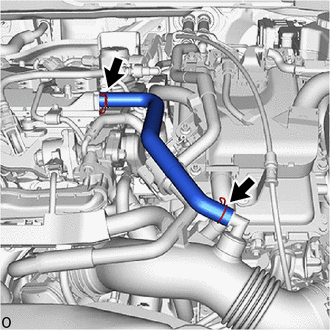
Check the PCV hose connections.
- OK:
PCV hose and PCV valve are connected correctly and are not damaged.
- Result:
Proceed to OK NG
OK
NG
Enter the following menus.
- Powertrain > Engine > Data List
-
Tester Display Misfire RPM Misfire Load - 50003 372 146,152
Read and note the Misfire RPM and Misfire Load values.
- HINT:
-
The Misfire RPM and Misfire Load values indicate the vehicle conditions under which the misfire occurred.
- Result:
Proceed to NEXT
NEXT
Enter the following menus.
- Powertrain > Engine > Data List
-
Tester Display Catalyst OT Misfire Fuel Cut - 50003 372 154
Read the value displayed on the GTS.
- Result:
Data List Result Proceed to Catalyst OT Misfire Fuel Cut Avail A Not Avl B
A
B
Using the GTS, confirm the vehicle conditions recorded in the Freeze Frame Data which were present when the DTC was stored.
- Powertrain > Engine > DTC(P030000) > Freeze Frame Data
-
Tester Display Catalyst OT Misfire Fuel Cut History - 50040 372 153 P030000
- Result:
Freeze Frame Data Item Result Proceed to Catalyst OT Misfire Fuel Cut History ON A OFF B
A
B
Put the engine in Inspection Mode (Maintenance Mode).
- Powertrain > Hybrid Control > Utility
-
Tester Display Inspection Mode - 50005 397 2103
Start the engine and warm it up until the engine coolant temperature reaches 75°C (167°F) or higher.
Enter the following menus.
- Powertrain > Engine > Active Test
-
Active Test Display Prohibit the Catalyst OT Misfire Prevent Fuel Cut -
Data List Display Coolant Temperature Injection Mode Misfire Count Cylinder #1 Misfire Count Cylinder #2 Misfire Count Cylinder #3 Misfire Count Cylinder #4 - 50004 372 42003 205,294,148,149,150,151
Read each value for Misfire Count Cylinder #1 to Misfire Count Cylinder #4 and Injection Mode displayed on the GTS while performing the Active Test.
- Result:
Injection Mode Misfire Count Proceed to Port 1 or 2 cylinders have misfire counts A 3 cylinders or more have misfire counts There are no misfire counts B
A
B
Put the engine in Inspection Mode (Maintenance Mode).
- Powertrain > Hybrid Control > Utility
-
Tester Display Inspection Mode - 50005 397 2103
Start the engine and warm it up until the engine coolant temperature reaches 75°C (167°F) or higher.
Enter the following menus.
- Powertrain > Engine > Active Test
-
Active Test Display Control the Injection Mode -
Data List Display Coolant Temperature Injection Mode Misfire Count Cylinder #1 Misfire Count Cylinder #2 Misfire Count Cylinder #3 Misfire Count Cylinder #4 - 50004 372 42004 205,294,148,149,150,151
According to the display on the GTS, read the Data List with the Active Test "Control the Injection Mode" set to Port. If no misfire counts occur in any cylinders, perform procedure [A] and [B] and then check the misfire counts again.
Drive the vehicle with the Misfire RPM and Misfire Load noted in the "Read Value Using GTS (Misfire RPM and Misfire Load)" procedures above [A].
- CAUTION:
-
When performing a driving test, obey all speed limits and traffic laws.
Read the Injection Mode and Misfire Count Cylinder #1 to Misfire Count Cylinder #4 or DTCs displayed on the GTS [B].
- Result:
Injection Mode Misfire Count Proceed to Port 1 or 2 cylinders have misfire counts A 3 cylinders or more have misfire counts There are no misfire counts B
A
B
Put the engine in Inspection Mode (Maintenance Mode).
- Powertrain > Hybrid Control > Utility
-
Tester Display Inspection Mode - 50005 397 2103
Start the engine and warm it up until the engine coolant temperature reaches 75°C (167°F) or higher.
Enter the following menus.
- Powertrain > Engine > Active Test
-
Active Test Display Control the Injection Mode -
Data List Display Coolant Temperature Injection Mode Misfire Count Cylinder #1 Misfire Count Cylinder #2 Misfire Count Cylinder #3 Misfire Count Cylinder #4 - 50004 372 42004 205,294,148,149,150,151
According to the display on the GTS, read the Data List with the Active Test "Control the Injection Mode" set to Direct. If no misfire counts occur in any cylinders, perform procedure [A] and [B] and then check the misfire counts again.
Drive the vehicle with the Misfire RPM and Misfire Load noted in the "Read Value Using GTS (Misfire RPM and Misfire Load)" procedures above [A].
- CAUTION:
-
When performing a driving test, obey all speed limits and traffic laws.
Read the Injection Mode and Misfire Count Cylinder #1 to Misfire Count Cylinder #4 or DTCs displayed on the GTS [B].
- Result:
Misfire Count Proceed to Port (Result of step 6 or 7) Direct 1 or 2 cylinders have misfire counts 1 or 2 cylinders have misfire counts A 3 cylinders or more have misfire counts 3 cylinders or more have misfire counts B 1 or 2 cylinders have misfire counts There are no misfire counts C 3 cylinders or more have misfire counts There are no misfire counts D
- HINT:
-
Perform "Inspection After Repair" after replacing the port fuel injector assembly.
A
B
C
D
Check the fuel pressure (for low pressure side).
- HINT:
-
Perform "Inspection After Repair" after replacing the port fuel injector assembly.
- Result:
Proceed to OK NG
OK
NG
Check the fuel lines for leaks or blockage.
- HINT:
-
Perform "Inspection After Repair" after replacing the fuel pump (for low pressure side).
- Result:
Proceed to OK NG
OK
NG
Put the engine in Inspection Mode (Maintenance Mode).
- Powertrain > Hybrid Control > Utility
-
Tester Display Inspection Mode - 50005 397 2103
Start the engine and warm it up until the engine coolant temperature reaches 75°C (167°F) or higher.
Enter the following menus.
- Powertrain > Engine > Active Test
-
Active Test Display Control the Injection Mode -
Data List Display Coolant Temperature Injection Mode Misfire Count Cylinder #1 Misfire Count Cylinder #2 Misfire Count Cylinder #3 Misfire Count Cylinder #4 - 50004 372 42004 205,294,148,149,150,151
According to the display on the GTS, read the Data List with the Active Test "Control the Injection Mode" set to Direct. If no misfire counts occur in any cylinders, perform procedure [A] and [B] and then check the misfire counts again.
Drive the vehicle with the Misfire RPM and Misfire Load noted in the "Read Value Using GTS (Misfire RPM and Misfire Load)" procedures above [A].
- CAUTION:
-
When performing a driving test, obey all speed limits and traffic laws.
Read the Injection Mode and Misfire Count Cylinder #1 to Misfire Count Cylinder #4 or DTCs displayed on the GTS [B].
- Result:
Misfire Count Proceed to Port (Result of step 6 or 7) Direct There are no misfire counts There are misfire counts A There are no misfire counts There are no misfire counts B
- HINT:
-
Perform "Inspection After Repair" after replacing the direct fuel injector assembly.
A
B
Clear the DTCs.
- Powertrain > Engine > Clear DTCs
- 50002 372
Turn the ignition switch off and wait for at least 30 seconds.
- Result:
Proceed to NEXT
NEXT
Put the engine in Inspection Mode (Maintenance Mode).
- Powertrain > Hybrid Control > Utility
-
Tester Display Inspection Mode - 50005 397 2103
Start the engine and warm it up until the engine coolant temperature reaches 75°C (167°F) or higher.
Enter the following menus.
- Powertrain > Engine > Data List
-
Tester Display Coolant Temperature Injection Mode Misfire Count Cylinder #1 Misfire Count Cylinder #2 Misfire Count Cylinder #3 Misfire Count Cylinder #4 Misfire RPM Misfire Load - 50003 372 205,294,148,149,150,151,146,152
Drive the vehicle with Misfire RPM and Misfire Load.
- CAUTION:
-
When performing a driving test, obey all speed limits and traffic laws.
Monitor all of the misfire count values and Injection Mode displayed on the GTS.
- Result:
Misfire Count Injection Mode Proceed to There are no misfire counts - A 1 or 2 cylinders have misfire counts Port or Either B 3 cylinders or more have misfire counts Port or Either C There are misfire counts Direct D
- HINT:
-
Perform "Inspection After Repair" after replacing the direct fuel injector assembly.
A
B
C
D
- HINT:
-
Perform "Inspection After Repair" after replacing the spark plug.
- Result:
Proceed to OK NG
OK
NG
Perform a spark test.
- HINT:
- ·
If the result of the spark test is normal, proceed to the next step.
·Perform "Inspection After Repair" after replacing the spark plug or ignition coil assembly.
- Result:
Proceed to NEXT
NEXT
Measure the cylinder compression pressure of the misfiring cylinder.
- HINT:
-
Perform "Inspection After Repair" after repairing or replacing the engine assembly.
- Result:
Proceed to OK NG
OK
NG
Check the intake system for vacuum leaks.
- OK:
No leaks from intake system.
- HINT:
-
Perform "Inspection After Repair" after repairing or replacing the intake system.
- Result:
Proceed to OK NG
OK
NG
Enter the following menus.
- Powertrain > Engine > Data List
-
Tester Display Coolant Temperature - 50003 372 205
Read the Data List twice, when the engine is both cold and warmed up.
- Standard:
GTS Display Condition Specified Condition Coolant Temperature Cold engine Same as ambient air temperature Warm engine Between 75 and 100°C (167 and 212°F)
- HINT:
-
Perform "Inspection After Repair" after replacing the engine coolant temperature sensor.
- Result:
Proceed to OK NG
OK
NG
Put the engine in Inspection Mode (Maintenance Mode).
- Powertrain > Hybrid Control > Utility
-
Tester Display Inspection Mode - 50005 397 2103
Start the engine and warm it up until the engine coolant temperature reaches 75°C (167°F) or higher.
Enter the following menus.
- Powertrain > Engine > Data List
-
Tester Display Engine Speed Mass Air Flow Sensor Coolant Temperature - 50003 372 211,215,205
Read Mass Air Flow Sensor while maintaining an engine speed of 2500 rpm.
- HINT:
-
During charge control, the engine speed is set at idle. Therefore, the engine speed will not increase when the accelerator pedal is depressed. In this case, read the Data List after charge control has completed.
- Standard:
GTS Display Condition Specified Condition Mass Air Flow Sensor ·Engine warmed up
·Shift position: P
·A/C: Off
·Engine Speed: 2500 rpm
Between 5.5 and 18.6 gm/sec
- Result:
Proceed to OK NG
OK
NG
Put the engine in Inspection Mode (Maintenance Mode).
- Powertrain > Hybrid Control > Utility
-
Tester Display Inspection Mode - 50005 397 2103
Start the engine and warm it up until the engine coolant temperature is 75°C (167°F) or higher.
- HINT:
-
The A/C switch and all accessories should be off.
Enter the following menus.
- Powertrain > Engine > Active Test
-
Active Test Display Control the EGR Step Position -
Data List Display Intake Manifold Absolute Pressure Coolant Temperature Engine Independent - 50004 372 25 385,205,428
Confirm that the value of Data List item Engine Independent is "Operate" then check the value of Intake Manifold Absolute Pressure while performing the Active Test.
- NOTICE:
- ·
Make sure that the value of Data List item Engine Independent is "Operate" while performing the Active Test.
·Do not leave the EGR valve open for 10 seconds or more during the Active Test.
·Be sure to return the EGR valve to step 0 when the Active Test is completed.
·Do not open the EGR valve 30 steps or more during the Active Test.
- OK:
The value of Intake Manifold Absolute Pressure changes in response to the EGR step position when the value of Engine Independent is "Operate".
- Standard:
- EGR Step Position (Active Test) 0 Steps 0 to 30 Steps Intake Manifold Absolute Pressure
(Data List)(EGR valve is fully closed) Intake Manifold Absolute Pressure value is at least +10 kPa (1.45 psi) higher than when EGR valve is fully closed
- HINT:
- ·
If the value of Data List item Engine Independent is "Not Opr" when the engine is idling, charge control is being performed. Perform the Active Test after charge control is complete ("Operate" is displayed).
·While performing the Active Test, if the increase in the value of Intake Manifold Absolute Pressure is small, the EGR valve assembly may be a malfunctioning.
·Even if the EGR valve assembly is malfunctioning, rough idling or an increase in the value of Intake Manifold Absolute Pressure may occur while performing the Active Test. However, the amount that the value of Intake Manifold Absolute Pressure increases will be smaller than normal.
- Result:
Proceed to OK NG
OK
NG
Remove the EGR valve assembly.
Check if the EGR valve is stuck open.
- OK:
EGR valve is tightly closed.
- HINT:
-
Perform "Inspection After Repair" after replacing the EGR valve assembly.
- Result:
Proceed to OK NG
OK
NG
Remove the cylinder head cover sub-assembly.
Turn the crankshaft pulley and align its groove with the TDC timing mark of the timing chain cover.
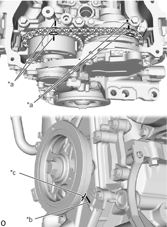
| *a | Timing Mark |
| *b | TDC Timing Mark |
| *c | Groove |
Check that the timing marks of the camshaft timing gear assembly and camshaft timing exhaust gear assembly are at the positions shown in the illustration.
- HINT:
-
If the timing marks are not as shown, turn the crankshaft one revolution clockwise.
- OK:
Timing marks on camshaft timing gear assembly and camshaft timing exhaust gear assembly are at the positions shown in the illustration.
- HINT:
-
If the result is not as specified, check for mechanical malfunctions that may have affected the valve timing, such as a jumped tooth or stretching of the timing chain.
- Result:
Proceed to OK NG
OK
NG
Check the connection and terminal contact pressure of connectors and wire harnesses between the mass air flow meter and ECM.
- HINT:
-
Repair any problems.
- Result:
Proceed to NEXT
NEXT
Clear the DTCs.
- Powertrain > Engine > Clear DTCs
- 50002 372
Turn the ignition switch off and wait for at least 30 seconds.
- Result:
Proceed to NEXT
NEXT
Drive the vehicle in accordance with the driving pattern described in Confirmation Driving Pattern.
Enter the following menus.
- Powertrain > Engine > Utility
-
Tester Display All Readiness - 50005 372 20
Input the DTC: P030000, P030027, P030085, P030100, P030200, P030300 or P030400.
Check the DTC judgment result.
- Result:
Result Proceed to NORMAL
(DTCs are not output)A ABNORMAL
(DTC P030000, P030027, P030085, P030100, P030200, P030300 and/or P030400 is output)B
A
B
Disconnect the mass air flow meter connector.
Disconnect the ECM connector.
Measure the resistance according to the value(s) in the table below.
- Standard Resistance:
Tester Connection Condition Specified Condition C26-4 (VCC) - C141-78 (VCVG) Always Below 1 Ω C26-3 (FG) - C141-101 (VG) Always Below 1 Ω C26-2 (E2G) - C141-79 (E2G) Always Below 1 Ω C26-4 (VCC) or C141-78 (VCVG) - Body ground and other terminals Always 10 kΩ or higher C26-3 (FG) or C141-101 (VG) - Body ground and other terminals Always 10 kΩ or higher C26-2 (E2G) or C141-79 (E2G) - Body ground and other terminals Always 10 kΩ or higher
- Result:
Proceed to OK NG
OK
NG
- HINT:
- ·
If the results of the inspections performed in step 19 (READ VALUE USING GTS (MASS AIR FLOW SENSOR)) indicated no problem, proceed to the next step without replacing the mass air flow meter.
·Perform "Inspection After Repair" after replacing the mass air flow meter.
- Result:
Proceed to NEXT
NEXT
Clear the DTCs.
- Powertrain > Engine > Clear DTCs
- 50002 372
Turn the ignition switch off and wait for at least 30 seconds.
- Result:
Proceed to NEXT
NEXT
Drive the vehicle in accordance with the driving pattern described in Confirmation Driving Pattern.
Enter the following menus.
- Powertrain > Engine > Utility
-
Tester Display All Readiness - 50005 372 20
Input the DTC: P030000, P030027, P030085, P030100, P030200, P030300 or P030400.
Check the DTC judgment result.
- Result:
Result Proceed to NORMAL
(DTCs are not output)A ABNORMAL
(DTC P030000, P030027, P030085, P030100, P030200, P030300 and/or P030400 is output)B
A
B