M20F-FXS, M20G-FXS FUEL FUEL INJECTOR(for Port Injection) REMOVAL
CAUTION / NOTICE / HINT
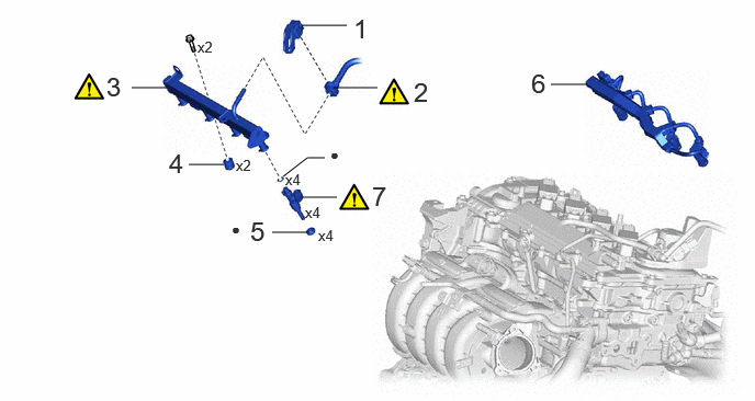
| Procedure | Part Name Code | 
|

|

|
|
|---|---|---|---|---|---|
| 1 | FUEL PIPE CLAMP | 23841K | - | - | - |
| 2 | FUEL TUBE SUB-ASSEMBLY | 23910A | ( 202307,999999,_51,_144959,_0604266,RM100000002BTTA_01_0084,) 202307,999999,_51,_144959,_0604266,RM100000002BTTA_01_0084,)
|
- | - |
| 3 | FUEL DELIVERY PIPE SUB-ASSEMBLY | 23807 | (202307,999999,_51,_144959,_0604266,RM100000002BTTA_01_0083,)
|
- | - |
| 4 | FUEL DELIVERY SPACER | 23891 | - | - | - |
| 5 | INJECTOR VIBRATION INSULATOR | 23291 | - | - | - |
| 6 | NO. 5 ENGINE WIRE | 82125N | - | - | - |
| 7 | PORT FUEL INJECTOR ASSEMBLY | 23250F | (202307,999999,_51,_144959,_0604266,RM100000002BTTA_01_0079,)
|
- | - |
| ● | Non-reusable part | - | - |
CAUTION / NOTICE / HINT
The necessary procedures (adjustment, calibration, initialization or registration) that must be performed after parts are removed and installed, or replaced during port fuel injector assembly removal/installation are shown below.
| Replaced Part or Performed Procedure | Necessary Procedure | Effect/Inoperative Function when Necessary Procedure not Performed | Link |
|---|---|---|---|
·
Replacement of port fuel injector assembly ·
Replacement of No. 2 fuel pressure sensor |
Inspection after repair | ·
Poor idle, etc. ·
Engine start function, etc. |
(202307,999999,_51,_144956,_0604911,RM100000002BWPD,)
|
- CAUTION:
- ·
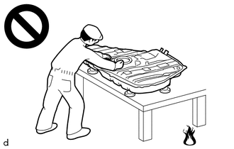
Never perform work on fuel system components near any possible ignition sources.
·Vaporized fuel could ignite, resulting in a serious accident.
- ·

Do not perform work on fuel system components without first disconnecting the cable from the negative (-) auxiliary battery terminal.
·Sparks could cause vaporized fuel to ignite, resulting in a serious accident.
- NOTICE:
- ·
After the ignition switch is turned off, the radio and display receiver assembly records various types of memory and settings. As a result, after turning the ignition switch off, make sure to wait at least 120 seconds before disconnecting the cable from the negative (-) auxiliary battery terminal.
·This procedure includes the removal of small-head bolts. Refer to Small-Head Bolts of Basic Repair Hint to identify the small-head bolts.
- HINT:
-
When the cable is disconnected/reconnected to the auxiliary battery terminal, systems temporarily stop operating. However, each system has a function that completes learning the first time the system is used.
- ·
Learning completes when vehicle is driven
Effect/Inoperative Function When Necessary Procedures are not Performed Necessary Procedures Link Front Camera System Drive the vehicle straight ahead at 15 km/h (10 mph) or more for 1 second or more. ( 202307,999999,_95,_112293,_0586709,RM100000002BSVY,)
·Learning completes when vehicle is operated normally
Effect/Inoperative Function When Necessary Procedures are not Performed Necessary Procedures Link Power door lock control system
·Back door opener
Perform door unlock operation with door control switch or electrical key transmitter sub-assembly switch. ( 202201,999999,_58,_115226,_0510939,RM1000000020BSY,)
Power back door system Fully close the back door by hand.
- HINT:
-
Initialization is not necessary if the above procedures are performed while the back door is closed.
( 202201,999999,_59,_113746,_0504731,RM100000001ZJKP,)
Air conditioning system After the ignition switch is turned to ON, the servo motor standard position is recognized. -
PROCEDURE

 23841K
1.REMOVE FUEL PIPE CLAMP
23841K
1.REMOVE FUEL PIPE CLAMP
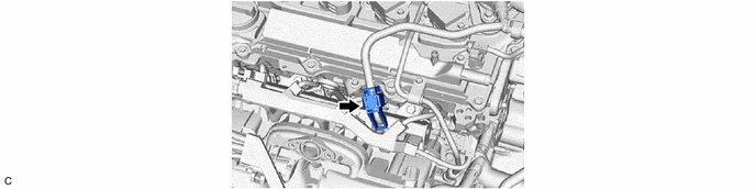
23910A
2.DISCONNECT FUEL TUBE SUB-ASSEMBLY
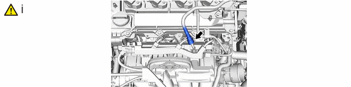
Disconnect the fuel tube sub-assembly from the fuel delivery pipe sub-assembly.
23807
3.REMOVE FUEL DELIVERY PIPE SUB-ASSEMBLY
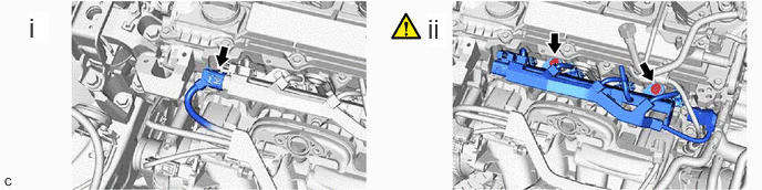
Disconnect the No. 5 engine wire connector.
Remove the 2 bolts and fuel delivery pipe sub-assembly with the 4 port fuel injector assemblies from the cylinder head sub-assembly.
- NOTICE:
-
Be careful not to drop the port fuel injector assemblies when removing the fuel delivery pipe sub-assembly.
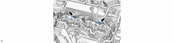
23891
4.REMOVE FUEL DELIVERY SPACER
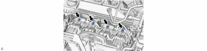
23291
5.REMOVE INJECTOR VIBRATION INSULATOR
82125N
6.REMOVE NO. 5 ENGINE WIRE
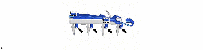
23250F
7.REMOVE PORT FUEL INJECTOR ASSEMBLY
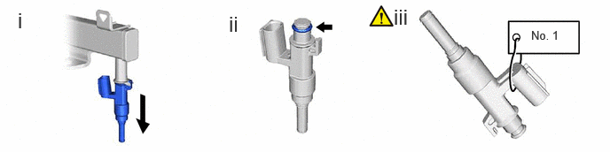
Pull the 4 port fuel injector assemblies out of the fuel delivery pipe sub-assembly.
Remove the O-ring from each port fuel injector assembly.
Attach a tag or label with the corresponding cylinder number to each port fuel injector assembly so that they can be installed to their original locations.
- NOTICE:
-
Cover the port fuel injector assemblies with plastic bags to prevent damage and contamination.