NAVIGATION / MULTI INFO DISPLAY NAVIGATION SYSTEM Speaker Circuit
DESCRIPTION
If there is a short in a speaker circuit, the stereo component amplifier assembly detects it and stops output to the speakers.
As a result, sound cannot be heard from the speakers even if there is no malfunction in the navigation receiver assembly, stereo component amplifier assembly or speakers.
WIRING DIAGRAM
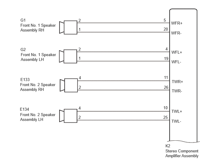
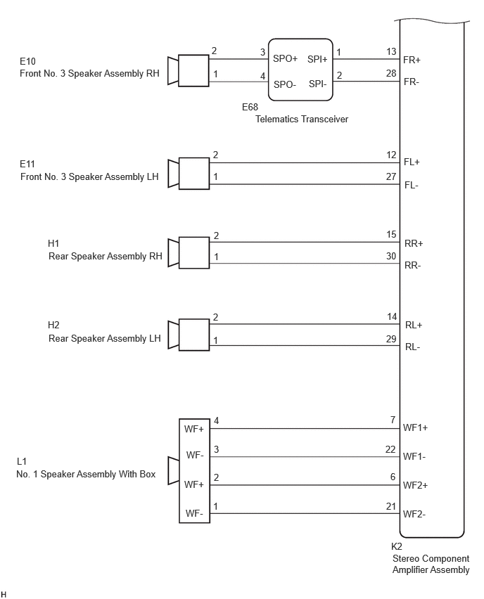
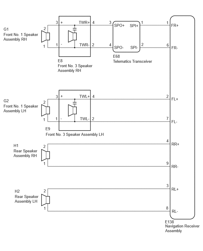
CAUTION / NOTICE / HINT
- NOTICE:
- ·
Depending on the parts that are replaced during vehicle inspection or maintenance, performing initialization, registration or calibration may be needed. Refer to Precaution for Navigation System.
·When replacing the telematics transceiver, make sure to replace it with a new one.
PROCEDURE
Choose the model to be inspected.
- Result:
Result Proceed to w/ "JBL" Sound System A w/o "JBL" Sound System B
A
B
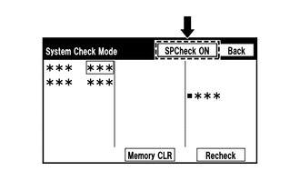
Select "Failure Diagnosis" from the "Service Menu" screen.
Select "System Check" from the "Failure Diagnosis" screen.
Select "SP Check ON" from the "System Check Mode" screen and perform speaker check.
- OK:
Each speaker outputs sound from the selected audio source properly.
- Result:
Result Proceed to Front No. 1 speaker assembly does not outputs sound A Front No. 2 speaker assembly does not outputs sound B Front No. 3 speaker assembly does not outputs sound C Rear speaker assembly does not outputs sound D No. 1 spealer assembly with box does not outputs sound E
A
B
C
D
E
Disconnect the K2 stereo component amplifier assembly connector.
Disconnect the G1 and G2 front No. 1 speaker assembly connector.
Measure the resistance according to the value(s) in the table below.
- Standard Resistance:
Tester Connection Condition Specified Condition Click Location & Routing(K2,G1,G2)Location & Routingewd_type=routing;type=c,c,c;code=K2,G1,G2
Click Connector(K2)Body>Floor Wire>Stereo Component Amplifier Assemblyewd_type=component;type=c;code=K2;pinno=5,20,4,19
Click Connector(G1)Body>Front Door Wire RH / Front Door Wire LH>Front No. 1 Speaker Assembly RHewd_type=component;type=c;code=G1;pinno=2,1
Click Connector(G2)Body>Front Door Wire RH / Front Door Wire LH>Front No. 1 Speaker Assembly LHewd_type=component;type=c;code=G2;pinno=2,1
K2-5 (WFR+) - G1-2 Always Below 1 Ω K2-20 (WFR-) - G1-1 Always Below 1 Ω K2-4 (WFL+) - G2-2 Always Below 1 Ω K2-19 (WFL-) - G2-1 Always Below 1 Ω K2-5 (WFR+) or G1-2 - Body ground Always 10 kΩ or higher K2-20 (WFR-) or G1-1 - Body ground Always 10 kΩ or higher K2-4 (WFL+) or G2-2 - Body ground Always 10 kΩ or higher K2-19 (WFL-) or G2-1 - Body ground Always 10 kΩ or higher
- Result:
Proceed to OK NG
OK
NG
- Result:
Proceed to OK NG
OK
NG
Disconnect the K2 stereo component amplifier assembly connector.
Disconnect the E133 and E134 front No. 2 speaker assembly connector.
Measure the resistance according to the value(s) in the table below.
- Standard Resistance:
Tester Connection Condition Specified Condition Click Location & Routing(K2,E133,E134)Location & Routingewd_type=routing;type=c,c,c;code=K2,E133,E134
Click Connector(K2)Body>Floor Wire>Stereo Component Amplifier Assemblyewd_type=component;type=c;code=K2;pinno=11,26,10,25
Click Connector(E133)Instrument Panel>Instrument Panel Wire / Telephone Computer Wire>Front No. 3 Speaker Assembly RHewd_type=component;type=c;code=E133;pinno=4,2
Click Connector(E134)Instrument Panel>Instrument Panel Wire / Telephone Computer Wire>Front No. 3 Speaker Assembly LHewd_type=component;type=c;code=E134;pinno=4,2
K2-11 (TWR+) - E133-4 Always Below 1 Ω K2-26 (TWR-) - E133-2 Always Below 1 Ω K2-10 (TWL+) - E134-4 Always Below 1 Ω K2-25 (TWL-) - E134-2 Always Below 1 Ω K2-11 (TWR+) or E133-4 - Body ground Always 10 kΩ or higher K2-26 (TWR-) or E133-2 - Body ground Always 10 kΩ or higher K2-10 (TWL+) or E134-4 - Body ground Always 10 kΩ or higher K2-25 (TWL-) or E134-2 - Body ground Always 10 kΩ or higher
- Result:
Proceed to OK NG
OK
NG
Replace the front No. 2 speaker assembly with a new or known good one.
Check if the malfunction disappears.
- Result:
Result Proceed to Malfunction disappears A Malfunction occurs B
A
B
Disconnect the K2 stereo component amplifier assembly connector.
Disconnect the E10 and E11 front No. 3 speaker assembly connector.
Disconnect the E68 Telematics Transceiver connector.
Measure the resistance according to the value(s) in the table below.
- Standard Resistance:
Tester Connection Condition Specified Condition Click Location & Routing(K2,E68,E10,E11)Location & Routingewd_type=routing;type=c,c,c,c;code=K2,E68,E10,E11
Click Connector(K2)Body>Floor Wire>Stereo Component Amplifier Assemblyewd_type=component;type=c;code=K2;pinno=13,28,12,27
Click Connector(E68)Instrument Panel>Instrument Panel Wire / Telephone Computer Wire>Telephone Transceiverewd_type=component;type=c;code=E68;pinno=1,2,3,4
Click Connector(E10)Instrument Panel>Instrument Panel Wire / Telephone Computer Wire>Front No. 2 Speaker Assembly RHewd_type=component;type=c;code=E10;pinno=2,1
Click Connector(E11)Instrument Panel>Instrument Panel Wire / Telephone Computer Wire>Front No. 2 Speaker Assembly LHewd_type=component;type=c;code=E11;pinno=2,1
K2-13 (FR+) - E68-1 (SPI+) Always Below 1 Ω K2-28 (FR-) - E68-2 (SPI-) Always Below 1 Ω E68-3 (SPO+) - E10-2 Always Below 1 Ω E68-4 (SPO-) - E10-1 Always Below 1 Ω K2-12 (FL+) - E11-2 Always Below 1 Ω K2-27 (FL-) - E11-1 Always Below 1 Ω K2-13 (FR+) or E68-1 (SPI+) - Body ground Always 10 kΩ or higher K2-28 (FR-) or E68-2 (SPI-) - Body ground Always 10 kΩ or higher E68-3 (SPO+) or E10-2 - Body ground Always 10 kΩ or higher E68-4 (SPO-) or E10-1 - Body ground Always 10 kΩ or higher K2-12 (FL+) or E11-2 - Body ground Always 10 kΩ or higher K2-27 (FL-) or E11-1 - Body ground Always 10 kΩ or higher
- Result:
Proceed to OK NG
OK
NG
Remove the Telematics Transceiver.
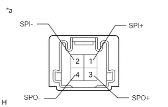
| *a | Component without harness connected
(Telematics Transceiver) |
Measure the resistance according to the value(s) in the table below.
- Standard Resistance:
Tester Connection Condition Specified Condition 1 (SPI+) - 3 (SPO+) Always Below 1 Ω 2 (SPI-) - 4 (SPO-) Always Below 1 Ω 1 (SPI+) - 2 (SPI-) Always 10 kΩ or higher 3 (SPO+) - 4 (SPO-) Always 10 kΩ or higher 1 (SPI+) or 3 (SPO+) - Body ground Always 10 kΩ or higher 2 (SPI-) or 4 (SPO-) - Body ground Always 10 kΩ or higher
- Result:
Proceed to OK NG
OK
NG
- Result:
Proceed to OK NG
OK
NG
Disconnect the K2 stereo component amplifier assembly connector.
Disconnect the H1 and H2 Rear speaker assembly connector.
Measure the resistance according to the value(s) in the table below.
- Standard Resistance:
Tester Connection Condition Specified Condition Click Location & Routing(K2,H1,H2)Location & Routingewd_type=routing;type=c,c,c;code=K2,H1,H2
Click Connector(K2)Body>Floor Wire>Stereo Component Amplifier Assemblyewd_type=component;type=c;code=K2;pinno=15,30,14,29
Click Connector(H1)Body>No. 1 Rear Door Wire / No. 2 Rear Door Wire>Rear Speaker Assembly RHewd_type=component;type=c;code=H1;pinno=2,1
Click Connector(H2)Body>No. 1 Rear Door Wire / No. 2 Rear Door Wire>Rear Speaker Assembly LHewd_type=component;type=c;code=H2;pinno=2,1
K2-15 (RR+) - H1-2 Always Below 1 Ω K2-30 (RR-) - H1-1 Always Below 1 Ω K2-14 (RL+) - H2-2 Always Below 1 Ω K2-29 (RL-) - H2-1 Always Below 1 Ω K2-15 (RR+) or H1-2 - Body ground Always 10 kΩ or higher K2-30 (RR-) or H1-1 - Body ground Always 10 kΩ or higher K2-14 (RL+) or H2-2 - Body ground Always 10 kΩ or higher K2-29 (RL-) or H2-1 - Body ground Always 10 kΩ or higher
- Result:
Proceed to OK NG
OK
NG
- Result:
Proceed to OK NG
OK
NG
Disconnect the K2 stereo component amplifier assembly connector.
Disconnect the L1 No. 1 speaker assembly with box connector.
Measure the resistance according to the value(s) in the table below.
- Standard Resistance:
Tester Connection Condition Specified Condition Click Location & Routing(K2,L1)Location & Routingewd_type=routing;type=c,c;code=K2,L1
Click Connector(K2)Body>Floor Wire>Stereo Component Amplifier Assemblyewd_type=component;type=c;code=K2;pinno=7,22,6,21
Click Connector(L1)Body>No. 2 Floor Wire>Rear No. 2 Speaker Assemblyewd_type=component;type=c;code=L1;pinno=4,3,2,1
K2-7 (WF1+) - L1-4 (WF+) Always Below 1 Ω K2-22 (WF1-) - L1-3 (WF-) Always Below 1 Ω K2-6 (WF2+) - L1-2 (WF+) Always Below 1 Ω K2-21 (WF2-) - L1-1 (WF-) Always Below 1 Ω K2-7 (WF1+) or L1-4 (WF+) - Body ground Always 10 kΩ or higher K2-22 (WF1-) or L1-3 (WF-) - Body ground Always 10 kΩ or higher K2-6 (WF2+) or L1-2 (WF+) - Body ground Always 10 kΩ or higher K2-21 (WF2-) or L1-1 (WF-) - Body ground Always 10 kΩ or higher
- Result:
Proceed to OK NG
OK
NG
- Result:
Proceed to OK NG
OK
NG
Select "Failure Diagnosis" from the "Service Menu" screen.
Select "System Check" from the "Failure Diagnosis" screen.
Select "SP Check ON" from the "System Check Mode" screen and perform speaker check.
- OK:
Each speaker outputs sound from the selected audio source properly.
- Result:
Result Proceed to Front No. 1 speaker assembly or front No. 2 speaker assembly does not outputs sound A Rear speaker assembly does not outputs sound B
A
B
Disconnect the E138 navigation receiver assembly connector.
Disconnect the G1 and G2 front No. 1 speaker assembly connectors.
Disconnect the E8 and E9 front No. 3 speaker assembly connectors.
Disconnect the E68 Telematics Transceiver connector.
Measure the resistance according to the value(s) in the table below.
- Standard Resistance:
Tester Connection Condition Specified Condition Click Location & Routing(E138,E9,E68,E8,G2,G1)Location & Routingewd_type=routing;type=c,c,c,c,c,c;code=E138,E9,E68,E8,G2,G1
Click Connector(E138)Instrument Panel>Instrument Panel Wire / Telephone Computer Wire>Navigation Receiver Assemblyewd_type=component;type=c;code=E138;pinno=2,7,1,6
Click Connector(E9)Instrument Panel>Instrument Panel Wire / Telephone Computer Wire>Front No. 2 Speaker Assembly LHewd_type=component;type=c;code=E9;pinno=4,2,3,1
Click Connector(E68)Instrument Panel>Instrument Panel Wire / Telephone Computer Wire>Telephone Transceiverewd_type=component;type=c;code=E68;pinno=1,2,3,4
Click Connector(E8)Instrument Panel>Instrument Panel Wire / Telephone Computer Wire>Front No. 2 Speaker Assembly RHewd_type=component;type=c;code=E8;pinno=4,2,3,1
Click Connector(G2)Body>Front Door Wire RH / Front Door Wire LH>Front No. 1 Speaker Assembly LHewd_type=component;type=c;code=G2;pinno=2,1
Click Connector(G1)Body>Front Door Wire RH / Front Door Wire LH>Front No. 1 Speaker Assembly RHewd_type=component;type=c;code=G1;pinno=2,1
E138-2 (FL+) - E9-4 (TWL+) Always Below 1 Ω E138-7 (FL-) - E9-2 (TWL-) Always Below 1 Ω E138-1 (FR+) - E68-1 (SPI+) Always Below 1 Ω E138-6 (FR-) - E68-2 (SPI-) Always Below 1 Ω E68-3 (SPO+) - E8-4 (TWR+) Always Below 1 Ω E68-4 (SPO-) - E8-2 (TWR-) Always Below 1 Ω G2-2 - E9-3 (+) Always Below 1 Ω G2-1 - E9-1 (-) Always Below 1 Ω G1-2 - E8-3 (+) Always Below 1 Ω G1-1 - E8-1 (-) Always Below 1 Ω E138-2 (FL+) or E9-4 (TWL+) - Body ground Always 10 kΩ or higher E138-7 (FL-) or E9-2 (TWL-) - Body ground Always 10 kΩ or higher E138-1 (FR+) or E68-1 (SPI+) - Body ground Always 10 kΩ or higher E138-6 (FR-) or E68-2 (SPI-) - Body ground Always 10 kΩ or higher E68-3 (SPO+) or E8-4 (TWR+) - Body ground Always 10 kΩ or higher E68-4 (SPO-) or E8-2 (TWR-) - Body ground Always 10 kΩ or higher G2-2 or E9-3 (+) - Body ground Always 10 kΩ or higher G2-1 or E9-1 (-) - Body ground Always 10 kΩ or higher G1-2 or E8-3 (+) - Body ground Always 10 kΩ or higher G1-1 or E8-1 (-) - Body ground Always 10 kΩ or higher
- Result:
Proceed to OK NG
OK
NG
Remove the Telematics Transceiver.
| *a | Component without harness connected
(Telematics Transceiver) |
Measure the resistance according to the value(s) in the table below.
- Standard Resistance:
Tester Connection Condition Specified Condition 1 (SPI+) - 3 (SPO+) Always Below 1 Ω 2 (SPI-) - 4 (SPO-) Always Below 1 Ω 1 (SPI+) - 2 (SPI-) Always 10 kΩ or higher 3 (SPO+) - 4 (SPO-) Always 10 kΩ or higher 1 (SPI+) or 3 (SPO+) - Body ground Always 10 kΩ or higher 2 (SPI-) or 4 (SPO-) - Body ground Always 10 kΩ or higher
- Result:
Proceed to OK NG
OK
NG
- Result:
Proceed to OK NG
OK
NG
Replace the front No. 3 speaker assembly with a new or known good one.
Check if the malfunction disappears.
- Result:
Result Proceed to Malfunction disappears A Malfunction occurs B
A
B
Disconnect the E138 navigation receiver assembly connector.
Disconnect the H1 and H2 rear speaker assembly connectors.
Measure the resistance according to the value(s) in the table below.
- Standard Resistance:
Tester Connection Condition Specified Condition Click Location & Routing(E138,H2,H1)Location & Routingewd_type=routing;type=c,c,c;code=E138,H2,H1
Click Connector(E138)Instrument Panel>Instrument Panel Wire / Telephone Computer Wire>Navigation Receiver Assemblyewd_type=component;type=c;code=E138;pinno=3,8,4,9
Click Connector(H2)Body>No. 1 Rear Door Wire / No. 2 Rear Door Wire>Rear Speaker Assembly LHewd_type=component;type=c;code=H2;pinno=2,1
Click Connector(H1)Body>No. 1 Rear Door Wire / No. 2 Rear Door Wire>Rear Speaker Assembly RHewd_type=component;type=c;code=H1;pinno=2,1
E138-3 (RL+) - H2-2 Always Below 1 Ω E138-8 (RL-) - H2-1 Always Below 1 Ω E138-4 (RR+) - H1-2 Always Below 1 Ω E138-9 (RR-) - H1-1 Always Below 1 Ω E138-3 (RL+) or H2-2 - Body ground Always 10 kΩ or higher E138-8 (RL-) or H2-1 - Body ground Always 10 kΩ or higher E138-4 (RR+) or H1-2 - Body ground Always 10 kΩ or higher E138-9 (RR-) or H1-1 - Body ground Always 10 kΩ or higher
- Result:
Proceed to OK NG
OK
NG
- Result:
Proceed to OK NG
OK
NG