NAVIGATION / MULTI INFO DISPLAY NAVIGATION SYSTEM B15C371 Speaker Output Short Actuator Stuck
DESCRIPTION
This DTC is stored when the stereo component amplifier assembly*1 or navigation receiver assembly*2 detects a short in a speaker circuit.
| DTC No. | Detection Item | DTC Detection Condition | Trouble Area |
|---|---|---|---|
| B15C371 | Speaker Output Short Actuator Stuck | When any of the following conditions is met:
(2 trip detection logic) ·
A short is detected in the speaker output circuit ·
Internal direct current is detected in the AMP power IC |
·
Harness or connector ·
Speaker ·
Stereo Component Amplifier*1 ·
Navigation Receiver Assembly*2 |
*1: w/ "JBL" Sound System
*2: w/o "JBL" Sound System
WIRING DIAGRAM
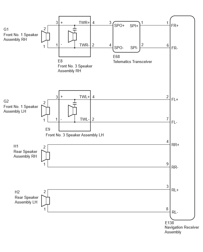
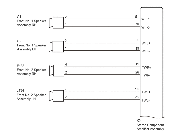
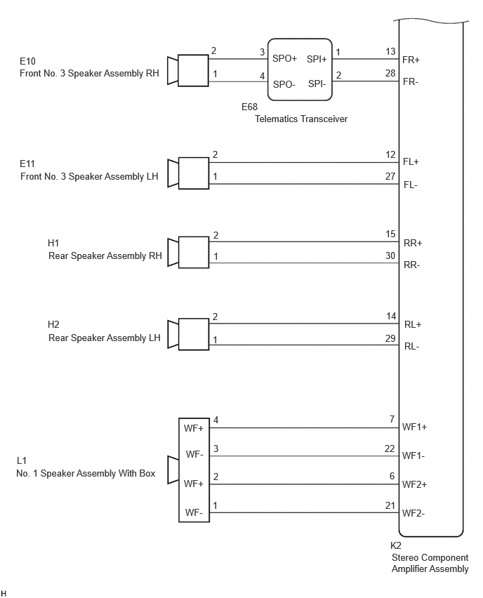
CAUTION / NOTICE / HINT
- NOTICE:
-
Depending on the parts that are replaced during vehicle inspection or maintenance, performing initialization, registration or calibration may be needed.
PROCEDURE
Choose the model to be inspected.
- Result:
Result Proceed to w/o "JBL" Sound System A w/ "JBL" Sound System B
A
B
Disconnect the E138 navigation receiver assembly connector.
Disconnect the E68 Telematics Transceiver connector.
Disconnect the E9 front No. 3 speaker assembly LH connector.
Disconnect the H1 and H2 rear speaker assembly connectors.
Measure the resistance according to the value(s) in the table below.
- Standard Resistance:
- Result:
Proceed to OK NG
OK
NG
Disconnect the E68 Telematics Transceiver connector.
Disconnect the E8 front No. 3 speaker assembly RH connector.
Measure the resistance according to the value(s) in the table below.
- Standard Resistance:
Tester Connection Condition Specified Condition Click Location & Routing(E68,E8)Location & Routingewd_type=routing;type=c,c;code=E68,E8
Click Connector(E68)Instrument Panel>Instrument Panel Wire / Telephone Computer Wire>Telephone Transceiverewd_type=component;type=c;code=E68;pinno=3,4
Click Connector(E8)Instrument Panel>Instrument Panel Wire / Telephone Computer Wire>Front No. 2 Speaker Assembly RHewd_type=component;type=c;code=E8;pinno=4,2
E68-3 (SPO+) or E8-4 (TWR+) - Body ground Always 10 kΩ or higher E68-4 (SPO-) or E8-2 (TWR-) - Body ground Always 10 kΩ or higher
- Result:
Proceed to OK NG
OK
NG
Remove the Telematics Transceiver.
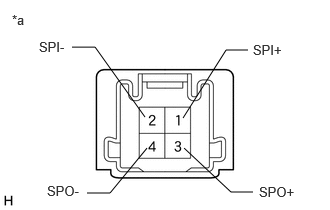
| *a | Component without harness connected
(Telematics Transceiver) |
Measure the resistance according to the value(s) in the table below.
- Standard Resistance:
Tester Connection Condition Specified Condition 1 (SPI+) - 3 (SPO+) Always Below 1 Ω 2 (SPI-) - 4 (SPO-) Always Below 1 Ω 1 (SPI+) - 2 (SPI-) Always 10 kΩ or higher 3 (SPO+) - 4 (SPO-) Always 10 kΩ or higher 1 (SPI+) or 3 (SPO+) - Body ground Always 10 kΩ or higher 2 (SPI-) or 4 (SPO-) - Body ground Always 10 kΩ or higher
- Result:
Proceed to OK NG
OK
NG
Disconnect the G1 and G2 front No. 1 speaker assembly connectors.
Disconnect the E8 and E9 front No. 3 speaker assembly connectors.
Measure the resistance according to the value(s) in the table below.
- Standard Resistance:
Tester Connection Condition Specified Condition Click Location & Routing(G1,E8,G2,E9)Location & Routingewd_type=routing;type=c,c,c,c;code=G1,E8,G2,E9
Click Connector(G1)Body>Front Door Wire RH / Front Door Wire LH>Front No. 1 Speaker Assembly RHewd_type=component;type=c;code=G1;pinno=2,1
Click Connector(E8)Instrument Panel>Instrument Panel Wire / Telephone Computer Wire>Front No. 2 Speaker Assembly RHewd_type=component;type=c;code=E8;pinno=3,1
Click Connector(G2)Body>Front Door Wire RH / Front Door Wire LH>Front No. 1 Speaker Assembly LHewd_type=component;type=c;code=G2;pinno=2,1
Click Connector(E9)Instrument Panel>Instrument Panel Wire / Telephone Computer Wire>Front No. 2 Speaker Assembly LHewd_type=component;type=c;code=E9;pinno=3,1
G1-2 or E8-3 (+) - Body ground Always 10 kΩ or higher G1-1 or E8-1 (-) - Body ground Always 10 kΩ or higher G2-2 or E9-3 (+) - Body ground Always 10 kΩ or higher G2-1 or E9-1 (-) - Body ground Always 10 kΩ or higher
- Result:
Proceed to OK NG
OK
NG
Remove the front No. 1 speaker assembly.
Inspect the front No. 1 speaker assembly.
- Result:
Proceed to OK NG
OK
NG
Remove the rear speaker assembly.
Inspect the rear speaker assembly.
- Result:
Proceed to OK NG
OK
NG
Replace the speaker assembly with a new or known good one.
- Result:
Proceed to NEXT
NEXT
Clear the DTCs.
- Body Electrical > Navigation System > Clear DTCs
- 50002 496
Turn the ignition switch off.
Check for DTCs and proceed to the following step.
- Body Electrical > Navigation System > Trouble Codes
- 50001 496
- Result:
Result Proceed to DTCs are not output A DTC B15C371 is output B
A
B
Disconnect the K2 stereo component amplifier assembly connector.
Disconnect the G1 and G2 front No. 1 speaker assembly connectors.
Disconnect the E10 and E11 front No. 3 speaker assembly connectors.
Disconnect the E133 and E134 front No. 2 speaker assembly connectors.
Disconnect the E68 telematics transceiver connector.
Disconnect the H1 and H2 rear speaker assembly connectors.
Disconnect the L1 No. 1 speaker assembly with box.
Measure the resistance according to the value (s) in the table below.
- Standard Resistance:
Tester Connection Condition Specified Condition Click Location & Routing(K2,E68,E11,E10,E133,E134,H1,H2,L1,G1,G2)Location & Routingewd_type=routing;type=c,c,c,c,c,c,c,c,c,c,c;code=K2,E68,E11,E10,E133,E134,H1,H2,L1,G1,G2
Click Connector(K2)Body>Floor Wire>Stereo Component Amplifier Assemblyewd_type=component;type=c;code=K2;pinno=13,28,12,27,11,26,10,25,15,30,14,29,7,22,6,21,5,20,4,19
Click Connector(E68)Instrument Panel>Instrument Panel Wire / Telephone Computer Wire>Telephone Transceiverewd_type=component;type=c;code=E68;pinno=1,2,3,4
Click Connector(E11)Instrument Panel>Instrument Panel Wire / Telephone Computer Wire>Front No. 2 Speaker Assembly LHewd_type=component;type=c;code=E11;pinno=2,1
Click Connector(E10)Instrument Panel>Instrument Panel Wire / Telephone Computer Wire>Front No. 2 Speaker Assembly RHewd_type=component;type=c;code=E10;pinno=2,1
Click Connector(E133)Instrument Panel>Instrument Panel Wire / Telephone Computer Wire>Front No. 3 Speaker Assembly RHewd_type=component;type=c;code=E133;pinno=4,2
Click Connector(E134)Instrument Panel>Instrument Panel Wire / Telephone Computer Wire>Front No. 3 Speaker Assembly LHewd_type=component;type=c;code=E134;pinno=4,2
Click Connector(H1)Body>No. 1 Rear Door Wire / No. 2 Rear Door Wire>Rear Speaker Assembly RHewd_type=component;type=c;code=H1;pinno=2,1
Click Connector(H2)Body>No. 1 Rear Door Wire / No. 2 Rear Door Wire>Rear Speaker Assembly LHewd_type=component;type=c;code=H2;pinno=2,1
Click Connector(L1)Body>No. 2 Floor Wire>Rear No. 2 Speaker Assemblyewd_type=component;type=c;code=L1;pinno=4,3,2,1
Click Connector(G1)Body>Front Door Wire RH / Front Door Wire LH>Front No. 1 Speaker Assembly RHewd_type=component;type=c;code=G1;pinno=2,1
Click Connector(G2)Body>Front Door Wire RH / Front Door Wire LH>Front No. 1 Speaker Assembly LHewd_type=component;type=c;code=G2;pinno=2,1
K2-13 (FR+) or E68-1 (SPI+) - Body ground Always 10 kΩ or higher K2-28 (FR-) or E68-2 (SPI-) - Body ground Always 10 kΩ or higher K2-12 (FL+) or E11-2 - Body ground Always 10 kΩ or higher K2-27 (FL-) or E11-1 - Body ground Always 10 kΩ or higher E68-3 (SPO+) or E10-2 - Body ground Always 10 kΩ or higher E68-4 (SPO-) or E10-1 - Body ground Always 10 kΩ or higher K2-11 (TWR+) or E133-4 - Body ground Always 10 kΩ or higher K2-26 (TWR-) or E133-2 - Body ground Always 10 kΩ or higher K2-10 (TWL+) or E134-4 - Body ground Always 10 kΩ or higher K2-25 (TWL-) or E134-2 - Body ground Always 10 kΩ or higher K2-15 (RR+) or H1-2 - Body ground Always 10 kΩ or higher K2-30 (RR-) or H1-1 - Body ground Always 10 kΩ or higher K2-14 (RL+) or H2-2 - Body ground Always 10 kΩ or higher K2-29 (RL-) or H2-1 - Body ground Always 10 kΩ or higher K2-7 (WF1+) or L1-4 (WF+) - Body ground Always 10 kΩ or higher K2-22 (WF1-) or L1-3 (WF-) - Body ground Always 10 kΩ or higher K2-6 (WF2+) or L1-2 (WF+) - Body ground Always 10 kΩ or higher K2-21 (WF2-) or L1-1 (WF-) - Body ground Always 10 kΩ or higher K2-5 (WFR+) or G1-2 - Body ground Always 10 kΩ or higher K2-20 (WFR-) or G1-1 - Body ground Always 10 kΩ or higher K2-4 (WFL+) or G2-2 - Body ground Always 10 kΩ or higher K2-19 (WFL-) or G2-1 - Body ground Always 10 kΩ or higher
- Result:
Proceed to OK NG
OK
NG
Remove the front No. 1 speaker assembly.
Inspect the front No. 1 speaker assembly.
- Result:
Proceed to OK NG
OK
NG
Remove the front No. 3 speaker assembly.
Inspect the front No. 3 speaker assembly.
- Result:
Proceed to OK NG
OK
NG
Remove the rear speaker assembly.
Inspect the rear speaker assembly.
- Result:
Proceed to OK NG
OK
NG
Remove the No. 1 speaker assembly with box.
Inspect the No. 1 speaker assembly with box.
- Result:
Proceed to OK NG
OK
NG
Remove the Telematics Transceiver.
| *a | Component without harness connected
(Telematics Transceiver) |
Measure the resistance according to the value(s) in the table below.
- Standard Resistance:
Tester Connection Condition Specified Condition 1 (SPI+) - 3 (SPO+) Always Below 1 Ω 2 (SPI-) - 4 (SPO-) Always Below 1 Ω 1 (SPI+) - 2 (SPI-) Always 10 kΩ or higher 3 (SPO+) - 4 (SPO-) Always 10 kΩ or higher 1 (SPI+) or 3 (SPO+) - Body ground Always 10 kΩ or higher 2 (SPI-) or 4 (SPO-) - Body ground Always 10 kΩ or higher
- Result:
Proceed to OK NG
OK
NG
Replace the speaker assembly with a new or known good one.
- Result:
Proceed to NEXT
NEXT
Clear the DTCs.
- Body Electrical > Navigation System > Clear DTCs
- 50002 496
Turn the ignition switch off.
Check for DTCs and proceed to the following step.
- Body Electrical > Navigation System > Trouble Codes
- 50001 496
- Result:
Result Proceed to DTCs are not output A DTC B15C371 is output B
A
B