SLIDING ROOF / CONVERTIBLE PANORAMIC FIXED MOONROOF WITH ONE-TOUCH FROSTED GLASS CONTROL SYSTEM Panoramic Fixed Moonroof with One-touch Frosted Glass Control does not Operate
DESCRIPTION
When the dimmable panoramic roof switch is operated, an operation request signal is sent to the main body ECU (multiplex network body ECU). The main body ECU (multiplex network body ECU) operates the dimmable panoramic roof glass (roof window glass assembly).
The roof sunshade ECU (sliding roof drive gear sub-assembly) operates the built-in motors based on each signal input from the dimmable panoramic roof switch and roof sunshade switch.
WIRING DIAGRAM
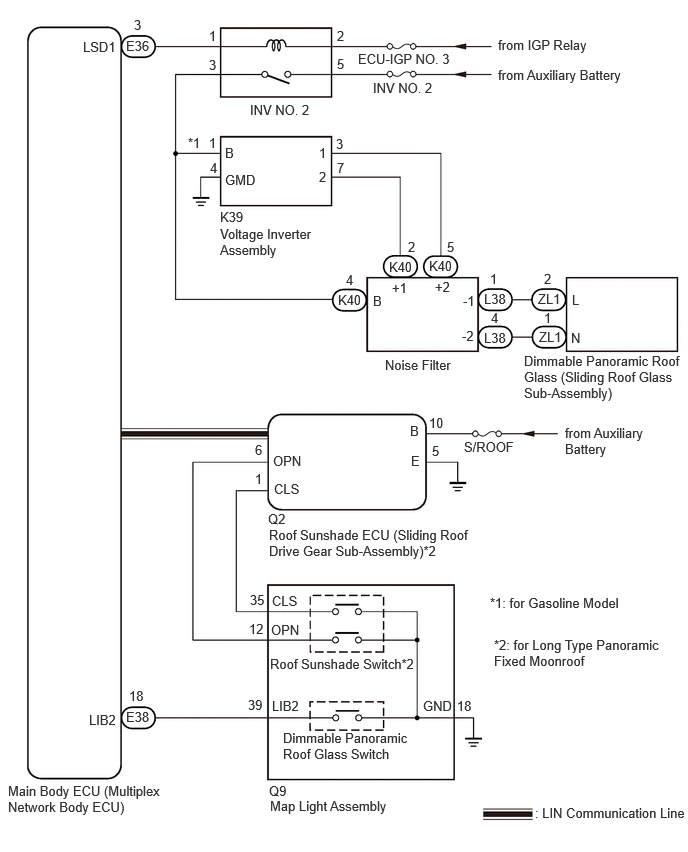
CAUTION / NOTICE / HINT
- NOTICE:
- ·
Inspect the fuses for circuits related to this system before performing the following procedure.
·If the roof sunshade ECU (sliding roof drive gear sub-assembly) is removed and reinstalled or replaced, the roof sunshade ECU (sliding roof drive gear sub-assembly) must be initialized.
·The panoramic fixed moonroof with one-touch frosted glass control system uses the LIN communication system. First, confirm that there are no malfunctions in the LIN communication system. Refer to How to Proceed with Troubleshooting.
PROCEDURE
Choose the model to be inspected.
- Result:
Result Proceed to for Short Type Panoramic Fixed Moon Roof A for Long Type Panoramic Fixed Moon Roof B
A
B
Perform the Active Test according to the display on the GTS.
- Body Electrical > Main Body > Active Test
-
Tester Display Measurement Item Control Range Diagnostic Note Light Control Glass Relay Light control glass relay operation OFF or ON -
- Body Electrical > Main Body > Active Test
-
Tester Display Light Control Glass Relay - 50004 449 93
- OK:
Slide roof is operated using GTS.
- Result:
Proceed to OK NG
OK
NG
Disconnect the Q9 dimmable panoramic roof glass switch (map light assembly) connector.
Disconnect the E38 main body ECU (multiplex network body ECU) connector.
Measure the resistance according to the value(s) in the table below.
- Standard Resistance:
Tester Connection Condition Specified Condition Click Location & Routing(Q9,E38)Location & Routingewd_type=routing;type=c,c;code=Q9,E38
Click Connector(Q9)Body>Roof Wire>Map Light Assemblyewd_type=component;type=c;code=Q9;pinno=39,18
Click Connector(E38)Instrument Panel>Instrument Panel Wire / Radio Wiring Sub-Assy / Telephone Computer Wire>Multiplex Network Body ECUewd_type=component;type=c;code=E38;pinno=18
Q9-39 (LIB2) - E38-18 (LIB2) Always Below 1 Ω Q9-39 (LIB2) or E38-18 (LIB2) - Body ground Always 10 kΩ or higher Q9-18 (GND) - Body ground Always Below 1 Ω
- Result:
Proceed to OK NG
OK
NG
- Result:
Result Proceed to Only the roof sunshade does not operate. A Only the dimmable panoramic roof glass does not operate. B The roof sunshade and dimmable panoramic roof glass do not operate. C
A
B
C
Read the Data List according to the display on the GTS.
- Body Electrical > Sliding Roof > Data List
-
Tester Display Measurement Item Range Normal Condition Diagnostic Note Open Switch OPEN switch signal OFF or ON OFF: OPEN switch not pressed
ON: OPEN switch pressed- Close Switch CLOSE switch signal OFF or ON OFF: CLOSE switch not pressed
ON: CLOSE switch pressed-
- Body Electrical > Sliding Roof > Data List
-
Tester Display Open Switch Close Switch - 50003 147 1,4
- OK:
The GTS display changes according to the operation of each switch as shown in the table.
- Result:
Proceed to OK NG
OK
NG
- Result:
Proceed to OK NG
OK
NG
Disconnect the Q2 roof sunshade ECU (sliding roof drive gear sub-assembly) connector.
Measure the resistance according to the value(s) in the table below.
- Standard Resistance:
Tester Connection Condition Specified Condition Click Location & Routing(Q2,Q9)Location & Routingewd_type=routing;type=c,c;code=Q2,Q9
Click Connector(Q2)Body>Roof Wire>Roof Sunshade Control ECU (Sliding Roof Drive Gear Assembly)ewd_type=component;type=c;code=Q2;pinno=1,6
Click Connector(Q9)Body>Roof Wire>Map Light Assemblyewd_type=component;type=c;code=Q9;pinno=35,12
Q2-1 (CLS) - Q9-35 (CLS) Always Below 1 Ω Q2-6 (OPN) - Q9-12 (OPN) Always Below 1 Ω
- Result:
Proceed to OK NG
OK
NG
Perform the Active Test according to the display on the GTS.
- Body Electrical > Main Body > Active Test
-
Tester Display Measurement Item Control Range Diagnostic Note Light Control Glass Relay Light control glass relay operation OFF or ON -
- Body Electrical > Main Body > Active Test
-
Tester Display Light Control Glass Relay - 50004 449 93
- OK:
Slide roof is operated using GTS.
- Result:
Proceed to OK NG
OK
NG
Disconnect the E38 main body ECU (multiplex network body ECU) connector.
Disconnect the Q9 dimmable panoramic roof glass switch (map light assembly) connector.
Measure the resistance according to the value(s) in the table below.
- Standard Resistance:
Tester Connection Condition Specified Condition Click Location & Routing(E38,Q9)Location & Routingewd_type=routing;type=c,c;code=E38,Q9
Click Connector(E38)Instrument Panel>Instrument Panel Wire / Radio Wiring Sub-Assy / Telephone Computer Wire>Multiplex Network Body ECUewd_type=component;type=c;code=E38;pinno=18
Click Connector(Q9)Body>Roof Wire>Map Light Assemblyewd_type=component;type=c;code=Q9;pinno=39
E38-18 (LIB2) - Q9-39 (LIB2) Always Below 1 Ω E38-18 (LIB2) or Q9-39 (LIB2) - Body ground Always 10 kΩ or higher
- Result:
Proceed to OK NG
OK
NG
- Result:
Proceed to OK NG
OK
NG
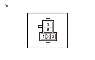
| *a | INV NO. 2 Relay Holder |
Measure the voltage according to the value(s) in the table below.
- Standard Voltage:
Tester Connection Condition Specified Condition INV NO. 2 relay holder terminal 2 - Body ground Ignition switch ON 11 to 14 V INV NO. 2 relay holder terminal 2 - Body ground Ignition switch off Below 1 V INV NO. 2 relay holder terminal 5 - Body ground Ignition switch off*1
Always*211 to 14 V
*1: for HV Model
*2: for Gasoline Model
- Result:
Proceed to OK NG
OK
NG
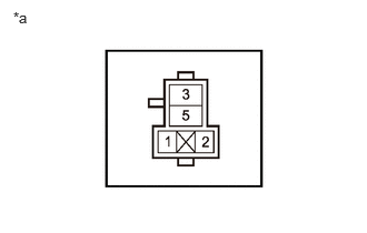
| *a | INV NO. 2 Relay Holder |
Disconnect the E36 main body ECU (multiplex network body ECU) connector.
Measure the resistance according to the value(s) in the table below.
- Standard Resistance:
Tester Connection Condition Specified Condition Click Location & Routing(E36)Location & Routingewd_type=routing;type=c;code=E36
Click Connector(E36)Instrument Panel>Instrument Panel Wire / Radio Wiring Sub-Assy / Telephone Computer Wire>Multiplex Network Body ECUewd_type=component;type=c;code=E36;pinno=3
INV NO. 2 relay holder terminal 1 - E36-3 (LSD1) Always Below 1 Ω INV NO. 2 relay holder terminal 1 or E36-3 (LSD1) - Body ground Always 10 kΩ or higher
- Result:
Proceed to OK NG
OK
NG
| *a | INV NO. 2 Relay Holder |
Disconnect the K39 voltage inverter assembly connector.
Disconnect the K40 noise filter connector.
Measure the resistance according to the value(s) in the table below.
- Standard Resistance:
Tester Connection Condition Specified Condition Click Location & Routing(K39,K40)Location & Routingewd_type=routing;type=c,c;code=K39,K40
Click Connector(K39)Body>Floor Wire>Voltage Inverter Assemblyewd_type=component;type=c;code=K39;pinno=1
Click Connector(K40)Body>Floor Wire>Noise Filterewd_type=component;type=c;code=K40;pinno=4
INV NO. 2 relay holder terminal 3 - K39-1 (B)* Always Below 1 Ω INV NO. 2 relay holder terminal 3 - K40-4 (B) Always Below 1 Ω INV NO. 2 relay holder terminal 3, K39-1 (B)* or K40-4 (B) - Body ground Always 10 kΩ or higher
*: for Gasoline Model
- Result:
Proceed to OK NG
OK
NG
Measure the resistance according to the value(s) in the table below.
- Standard Resistance:
Tester Connection Condition Specified Condition Click Location & Routing(K39)Location & Routingewd_type=routing;type=c;code=K39
Click Connector(K39)Body>Floor Wire>Voltage Inverter Assemblyewd_type=component;type=c;code=K39;pinno=4
K39-4 (GMD) - Body ground Always Below 1 Ω
- Result:
Proceed to OK NG
OK
NG
Measure the resistance according to the value(s) in the table below.
- Standard Resistance:
Tester Connection Condition Specified Condition Click Location & Routing(K39,K40)Location & Routingewd_type=routing;type=c,c;code=K39,K40
Click Connector(K39)Body>Floor Wire>Voltage Inverter Assemblyewd_type=component;type=c;code=K39;pinno=3,7
Click Connector(K40)Body>Floor Wire>Noise Filterewd_type=component;type=c;code=K40;pinno=5,2
K39-3 (1) - K40-5 (+2) Always Below 1 Ω K39-3 (1) or K40-5 (+2) - Body ground Always 10 kΩ or higher K39-7 (2) - K40-2 (+1) Always Below 1 Ω K39-7 (2) or K40-2 (+1) - Body ground Always 10 kΩ or higher
- Result:
Proceed to OK NG
OK
NG
- CAUTION:
- ·
Make sure to wear insulating gloves and safety glasses.
·Make sure not to cross the electrodes of an electrical tester measurement terminals.
Reconnect the K39 voltage inverter assembly connector.
Reconnect the E36 main body ECU (multiplex network body ECU) connector.
Reconnect the K40 noise filter connector.
Install the INV NO. 2 relay to the No. 2 engine room relay block and No. 2 engine room junction block assembly.
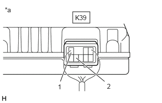
| *a | Component with harness connected
(Voltage Inverter Assembly) |
Measure the voltage according to the value(s) in the table below.
- HINT:
-
This is an AC voltage test.
- Standard Voltage:
Tester Connection Condition Specified Condition Click Location & Routing(K39)Location & Routingewd_type=routing;type=c;code=K39
Click Connector(K39)Body>Floor Wire>Voltage Inverter Assemblyewd_type=component;type=c;code=K39;pinno=3,7
K39-3 (1) - K39-7 (2) ·Tester changed to AC voltage setting
·Ignition switch ON, dimmable panoramic roof glass switch on
90 to 158 V K39-3 (1) - K39-7 (2) Ignition switch ON, dimmable panoramic roof glass switch off Below 1 V
- Result:
Proceed to OK NG
OK
NG
Disconnect the L38 noise filter connector.
Disconnect the ZL1 dimmable panoramic roof glass (sliding roof glass sub-assembly) connector.
Measure the resistance according to the value(s) in the table below.
- Standard Resistance:
Tester Connection Condition Specified Condition Click Location & Routing(L38,ZL1)Location & Routingewd_type=routing;type=c,w;code=L38,ZL1
Click Connector(L38)Body>No. 2 Floor Wire>Noise Filterewd_type=component;type=c;code=L38;pinno=1,4
Click Connector(ZL1)Body>Roof Glass Wire / Fuel Gage Wire>Roof Glass Wire and No. 2 Floor Wireewd_type=component;type=w;code=ZL1;pinno=2,1
L38-1 (-1) - ZL1-2 (L) Always Below 1 Ω L38-1 (-1) or ZL1-2 (L) - Body ground Always 10 kΩ or higher L38-4 (-2) - ZL1-1 (N) Always Below 1 Ω L38-4 (-2) or ZL1-1 (N) - Body ground Always 10 kΩ or higher
- Result:
Proceed to OK NG
OK
NG
- CAUTION:
- ·
Make sure to wear insulating gloves and safety glasses.
·Make sure not to cross the electrodes of an electrical tester measurement terminals.
Reconnect the ZL1 dimmable panoramic roof glass (sliding roof glass sub-assembly) connector.
Reconnect the K40 noise filter connector.
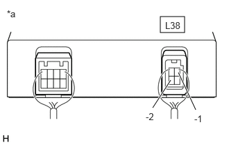
| *a | Component with harness connected
(Noise Filter) |
Measure the voltage according to the value(s) in the table below.
- HINT:
-
This is an AC voltage test.
- Standard Voltage:
Tester Connection Condition Specified Condition Click Location & Routing(L38)Location & Routingewd_type=routing;type=c;code=L38
Click Connector(L38)Body>No. 2 Floor Wire>Noise Filterewd_type=component;type=c;code=L38;pinno=1,4
L38-1 (-1) - L38-4 (-2) ·Tester changed to AC voltage setting
·Ignition switch ON, dimmable panoramic roof glass switch on
90 to 158 V L38-1 (-1) - L38-4 (-2) Ignition switch ON, dimmable panoramic roof glass switch off Below 1 V
- Result:
Proceed to OK NG
OK
NG
Disconnect the Q9 map light assembly connector.
Measure the resistance according to the value(s) in the table below.
- Standard Resistance:
Tester Connection Condition Specified Condition Click Location & Routing(Q9)Location & Routingewd_type=routing;type=c;code=Q9
Click Connector(Q9)Body>Roof Wire>Map Light Assemblyewd_type=component;type=c;code=Q9;pinno=18
Q9-18 (GND) - Body ground Always Below 1 Ω
- Result:
Proceed to OK NG
OK
NG