DOOR / HATCH POWER BACK DOOR SYSTEM Power Back Door cannot be Operated Using Any Switch
DESCRIPTION
If the power back door system cannot be operated using any switch, the multiplex network door ECU may not have been initialized, or there may be a malfunction in the power back door sensor assembly circuit, CAN communication system, back door closer, meter/gauge system, multiplex network door ECU power source circuit, or multiplex network door ECU.
WIRING DIAGRAM

CAUTION / NOTICE / HINT
- NOTICE:
- ·
The power back door system uses the CAN communication system. Inspect the communication function by following How to Proceed with Troubleshooting. Troubleshoot the power back door system after confirming that the CAN communication system is functioning properly.
·Inspect the fuses for circuits related to this system before performing the following procedure.
·If the multiplex network door ECU has been removed and installed or replaced, or if any of the connectors have been disconnected, initialize the power back door system.
·If the 2-step unlock function is enabled via customize settings, only the driver door unlocks when the first unlock operation is performed and the power back door does not operate as all the doors are not unlocked.
PROCEDURE
Read the customize setting "Unlock Key Twice Function" according to the display on the GTS.
- Result:
Result Proceed to The customize setting is "Disable" A The customize setting is "Enable" B
A
B
Read the customize setting "Wireless Unlock Twice Function" according to the display on the GTS.
- Result:
Result Proceed to The customize setting is "Disable" A The customize setting is "Enable" B
A
B
Read the customize setting "Entry Unlock Twice Function" according to the display on the GTS.
for Gasoline Model: Click hereVehicle Interior>THEFT DETERRENT / KEYLESS ENTRY>SMART ENTRY AND START SYSTEM (for Entry Function, Gasoline Model)>CUSTOMIZE PARAMETERS202111,202203,_58,_111832,_0509383,RM10000000204XA,202203,999999,_58,_111832,_0509383,RM1000000022FOO,
- Result:
Result Proceed to The customize setting is "Disable" A The customize setting is "Enable" B
A
B
Check that the shift position indicator operates correctly and the speedometer indicates 0 km/h (0 mph) when the vehicle is stopped with the hybrid control system*1 or engine*2 started.
*1: for HV Model
*2: for Gasoline Model
- OK:
Combination meter operates normally
- Result:
Proceed to OK NG
OK
NG
for Optitron Meter Type: Click hereVehicle Interior>METER / GAUGE / DISPLAY>METER / GAUGE SYSTEM (for Optitron Meter Type)>HOW TO PROCEED WITH TROUBLESHOOTING202111,999999,_58,_111835,_0504957,RM100000001ZKLL,
for TFT Meter Type: Click hereVehicle Interior>METER / GAUGE / DISPLAY>METER / GAUGE SYSTEM (for TFT Meter Type)>HOW TO PROCEED WITH TROUBLESHOOTING202111,999999,_58,_111835,_0504958,RM100000001ZKMB,
Check for DTCs.
- Body Electrical > Back Door > Trouble Codes
- 50001 489
- OK:
DTC is not output
- Result:
Proceed to OK NG
OK
NG
Read the Data List according to the display on the GTS.
- Body Electrical > Back Door > Data List
-
Tester Display Measurement Item Range Normal Condition Diagnostic Note Half Latch Switch Latch switch signal ON or OFF Back door opened condition: ON
Back door closed condition: OFF- Closer Position Switch Initial switch signal ON or OFF Back door opened condition: ON
Back door closed condition: ON- Pawl Switch Pawl switch signal ON or OFF Back door opened condition: OFF
Back door closed condition: OFF- Courtesy Switch Back door courtesy switch signal ON or OFF Back door opened condition: ON
Back door closed condition: OFF-
- Body Electrical > Back Door > Data List
-
Tester Display Half Latch Switch Closer Position Switch Pawl Switch Courtesy Switch - 50003 489 1003,1005,1017,1018
- Result:
Result Proceed to The ON/OFF switches normally depending on the back door condition (open or close). A The ON/OFF not switches normally depending on the back door condition (open or close). B
A
B
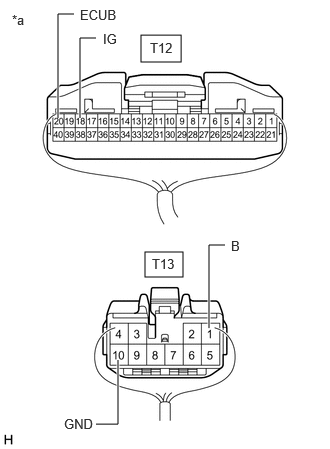
| *a | Rear view of wire harness connector
(to Multiplex Network Door ECU) |
Measure the resistance according to the value(s) in the table below.
- Standard Resistance:
Tester Connection Condition Specified Condition Click Location & Routing(T13)Location & Routingewd_type=routing;type=c;code=T13
Click Connector(T13)Body>No. 1 Back Door Wire>Multiplex Network Door ECUewd_type=component;type=c;code=T13;pinno=10
T13-10 (GND) - Body ground Always Below 1 Ω
Measure the voltage according to the value(s) in the table below.
- Standard Voltage:
Tester Connection Condition Specified Condition Click Location & Routing(T12,T13)Location & Routingewd_type=routing;type=c,c;code=T12,T13
Click Connector(T12)Body>No. 1 Back Door Wire>Multiplex Network Door ECUewd_type=component;type=c;code=T12;pinno=20,18
Click Connector(T13)Body>No. 1 Back Door Wire>Multiplex Network Door ECUewd_type=component;type=c;code=T13;pinno=1
T12-20 (ECUB) - Body ground Ignition switch off 11 to 14 V T13-1 (B) - Body ground Ignition switch off 11 to 14 V T12-18 (IG) - Body ground Ignition switch ON 11 to 14 V Ignition switch off Below 1 V
- Result:
Proceed to OK NG
OK
NG
Read the Data List according to the display on the GTS.
- Body Electrical > Back Door > Data List
-
Tester Display Measurement Item Range Normal Condition Diagnostic Note PBD Main Switch Power back door ON/OFF signal ON or OFF Current customize setting displayed Setting can be changed on "System Setting" on the multi-information display
- Body Electrical > Back Door > Data List
-
Tester Display PBD Main Switch - 50003 489 1037
- OK:
The display is as specified in the normal condition column.
- Result:
Proceed to OK NG
OK
NG
for Optitron Meter Type: Click hereVehicle Interior>METER / GAUGE / DISPLAY>METER / GAUGE SYSTEM (for Optitron Meter Type)>HOW TO PROCEED WITH TROUBLESHOOTING202111,999999,_58,_111835,_0504957,RM100000001ZKLL,
for TFT Meter Type: : Click hereVehicle Interior>METER / GAUGE / DISPLAY>METER / GAUGE SYSTEM (for TFT Meter Type)>HOW TO PROCEED WITH TROUBLESHOOTING202111,999999,_58,_111835,_0504958,RM100000001ZKMB,
Read the Data List according to the display on the GTS.
- Body Electrical > Back Door > Data List
-
Tester Display Measurement Item Range Normal Condition Diagnostic Note PBD Touch Sensor RH Power back door sensor assembly RH signal ON, OFF or Open ON: Power back door sensor assembly RH pressed
OFF: Power back door sensor assembly RH not pressed
Open: Power back door sensor assembly RH circuit open- PBD Touch Sensor LH Power back door sensor assembly LH signal ON, OFF or Open ON: Power back door sensor assembly LH pressed
OFF: Power back door sensor assembly LH not pressed
Open: Power back door sensor assembly LH circuit open-
- Body Electrical > Back Door > Data List
-
Tester Display PBD Touch Sensor RH PBD Touch Sensor LH - 50003 489 1057,1058
- Result:
Result Proceed to The values of Data List items "PBD Touch Sensor RH" and "PBD Touch Sensor LH" change to "ON" or "OFF" in accordance with the operation of the sensors. A The value of Data List item "PBD Touch Sensor RH" does not change to "ON" or "OFF" in accordance with the operation of the power back door sensor assembly RH. B The value of Data List item "PBD Touch Sensor LH" does not change to "ON" or "OFF" in accordance with the operation of the power back door sensor assembly LH. C
A
B
C
- Result:
Proceed to OK NG
OK
NG
Disconnect the T12 multiplex network door ECU connector.
Measure the resistance according to the value(s) in the table below.
- Standard Resistance:
Tester Connection Condition Specified Condition Click Location & Routing(T5,T12)Location & Routingewd_type=routing;type=c,c;code=T5,T12
Click Connector(T5)Body>No. 1 Back Door Wire>Power Back Door Sensor Assembly RHewd_type=component;type=c;code=T5;pinno=1,2
Click Connector(T12)Body>No. 1 Back Door Wire>Multiplex Network Door ECUewd_type=component;type=c;code=T12;pinno=6,24
T5-1 (OSR) - T12-6 (OSR) Always Below 1 Ω T5-2 (OSRE) - T12-24 (OSE) Always Below 1 Ω T5-1 (OSR) or T12-6 (OSR) - Body ground Always 10 kΩ or higher T5-2 (OSRE) or T12-24 (OSE) - Body ground Always 10 kΩ or higher
- Result:
Proceed to OK NG
OK
NG
- Result:
Proceed to OK NG
OK
NG
Disconnect the T12 multiplex network door ECU connector.
Measure the resistance according to the value(s) in the table below.
- Standard Resistance:
Tester Connection Condition Specified Condition Click Location & Routing(T6,T12)Location & Routingewd_type=routing;type=c,c;code=T6,T12
Click Connector(T6)Body>No. 1 Back Door Wire>Power Back Door Sensor Assembly LHewd_type=component;type=c;code=T6;pinno=1,2
Click Connector(T12)Body>No. 1 Back Door Wire>Multiplex Network Door ECUewd_type=component;type=c;code=T12;pinno=26,24
T6-1 (OSL) - T12-26 (OSL) Always Below 1 Ω T6-2 (OSLE) - T12-24 (OSE) Always Below 1 Ω T6-1 (OSL) or T12-26 (OSL) - Body ground Always 10 kΩ or higher T6-2 (OSLE) or T12-24 (OSE) - Body ground Always 10 kΩ or higher
- Result:
Proceed to OK NG
OK
NG
- Result:
Proceed to OK NG
OK
NG
Click hereVehicle Interior>DOOR LOCK>BACK DOOR LOCK>REMOVAL202111,999999,_58,_111830,_0501509,RM100000001Z6GX,
Disconnect the T13 multiplex network door ECU connector.
Disconnect the T8 back door lock with courtesy light switch assembly connector.
Measure the resistance according to the value(s) in the table below.
- Standard Resistance:
Tester Connection Condition Specified Condition Click Location & Routing(T13,T8)Location & Routingewd_type=routing;type=c,c;code=T13,T8
Click Connector(T13)Body>No. 1 Back Door Wire>Multiplex Network Door ECUewd_type=component;type=c;code=T13;pinno=4,3
Click Connector(T8)Body>No. 1 Back Door Wire>Back Door Lock Assembly with Courtesy Light Switchewd_type=component;type=c;code=T8;pinno=2,1
T13-4 (DC+) - T8-2 (M+) Always Below 1 Ω T13-3 (DC-) - T8-1 (M-) Always Below 1 Ω T13-4 (DC+) or T8-2 (M+) - Body ground Always 10 kΩ or higher T13-3 (DC-) or T8-1 (M-) - Body ground Always 10 kΩ or higher
- Result:
Proceed to OK NG
OK
NG