DOOR LOCK BACK DOOR LOCK INSPECTION
PROCEDURE

 69350P
1.INSPECT BACK DOOR LOCK ASSEMBLY WITH COURTESY LIGHT SWITCH (w/o Power Back Door)
69350P
1.INSPECT BACK DOOR LOCK ASSEMBLY WITH COURTESY LIGHT SWITCH (w/o Power Back Door)
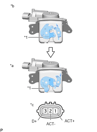
| *1 | Latch |
| *a | Open |
| *b | Close |
| *c | Component without harness connected
(Back Door Lock with Courtesy Light Switch Assembly) |
Check the operation of the door lock motor.
Move the back door lock with courtesy light switch assembly to the close position.
Apply auxiliary battery voltage to the door lock motor assembly and check the operation of the door lock motor.
- OK:
Auxiliary Battery Connection Specified Condition Auxiliary battery positive (+) → 1 (ACT+)
Auxiliary battery negative (-) → 2 (ACT-)Close → Open
If the result is not as specified, replace the back door lock with courtesy light switch assembly.
Check the operation of the door courtesy switch.
Measure the resistance according to the value(s) in the table below.
- Standard Resistance:
Tester Connection Switch Condition Specified Condition 2 (ACT-) - 3 (D+) Close 10 kΩ or higher 2 (ACT-) - 3 (D+) Open Below 1 Ω
If the result is not as specified, replace the back door lock with courtesy light switch assembly.
69350P
2.INSPECT BACK DOOR LOCK ASSEMBLY WITH COURTESY LIGHT SWITCH (w/ Power Back Door)
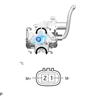
| *a | Open Operation Direction |
| *b | Close Operation Direction |
| *c | Component without harness connected
(Back Door Lock Assembly with Courtesy Light Switch) |
Check the operation.
Apply auxiliary battery voltage to the door lock motor and check the operation of the door lock motor.
- OK:
Battery Connection Result Auxiliary battery positive (+) → 1 (M-)
Auxiliary battery negative (-) → 2 (M+)Open Operation Auxiliary battery positive (+) → 2 (M+)
Auxiliary battery negative (-) → 1 (M-)Close Operation
If the result is not as specified, replace the back door lock assembly with courtesy light switch.
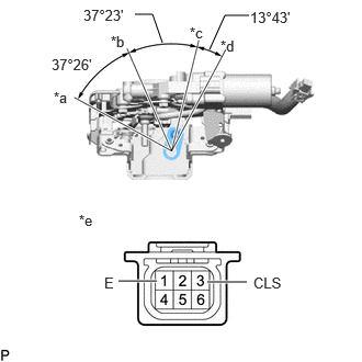
| *a | Open Position |
| *b | Half-latch Position |
| *c | Full-latch Position |
| *d | Overstroke Position |
| *e | Component without harness connected
(Back Door Lock with Courtesy Light Switch Assembly) |
Check the resistance of the half latch switch.
Measure the resistance according to the value(s) in the table below.
- Standard Resistance:
Tester Connection Condition Specified Condition 1 (E) - 3 (CLS) Open position Below 1 Ω 1 (E) - 3 (CLS) Open position → Half-latch position Below 1 Ω → 10 kΩ or higher 1 (E) - 3 (CLS) Half-latch position 10 kΩ or higher 1 (E) - 3 (CLS) Full-latch position 10 kΩ or higher 1 (E) - 3 (CLS) Overstroke position 10 kΩ or higher
If the result is not as specified, replace the back door lock assembly with courtesy light switch.
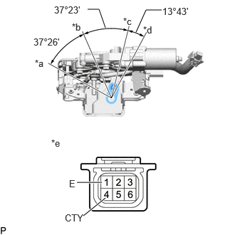
| *a | Open Position |
| *b | Half-latch Position |
| *c | Full-latch Position |
| *d | Overstroke Position |
| *e | Component without harness connected
(Back Door Lock with Courtesy Light Switch Assembly) |
Check the resistance of the full latch switch.
Measure the resistance according to the value(s) in the table below.
- Standard Resistance:
Tester Connection Condition Specified Condition 4 (CTY) - 1 (E) Open position Below 1 Ω 4 (CTY) - 1 (E) Half-latch position Below 1 Ω 4 (CTY) - 1 (E) Half-latch position → Full-latch position Below 1 Ω → 10 kΩ or higher 4 (CTY) - 1 (E) Full-latch position 10 kΩ or higher 4 (CTY) - 1 (E) Overstroke position 10 kΩ or higher
If the result is not as specified, replace the back door lock assembly with courtesy light switch.
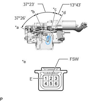
| *a | Open Position |
| *b | Half-latch Position |
| *c | Full-latch Position |
| *d | Overstroke Position |
| *e | Component without harness connected
(Back Door Lock with Courtesy Light Switch Assembly) |
Check the resistance of the pawl switch.
Measure the resistance according to the value(s) in the table below.
- Standard Resistance:
Tester Connection Condition Specified Condition 2 (FSW) - 1 (E) Open-latch 10 kΩ or higher 2 (FSW) - 1 (E) Open position → Half-latch position 10 kΩ or higher → Below 1 Ω → 10 kΩ or higher 2 (FSW) - 1 (E) Half-latch position 10 kΩ or higher 2 (FSW) - 1 (E) Half-latch position → Full-latch position 10 kΩ or higher → Below 1 Ω → 10 kΩ or higher 2 (FSW) - 1 (E) Full-latch position 10 kΩ or higher 2 (FSW) - 1 (E) Overstroke position 10 kΩ or higher
If the result is not as specified, replace the back door lock assembly with courtesy light switch.
Check the operation of the selector switch.
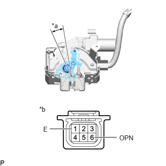
| *a | Sector Gear in Neutral Position |
| *b | Component without harness connected
(Back Door Lock Assembly with Courtesy Light Switch) |
Measure the resistance according to the value(s) in the table below.
- Standard Resistance:
Tester Connection Condition Specified Condition 6 (OPN) - 1 (E) Selector gear in neutral position
(Selector switch on)Below 1 Ω 6 (OPN) - 1 (E) Selector gear not in neutral position
(Selector switch off)10 kΩ or higher
If the result is not as specified, replace the back door lock assembly with courtesy light switch.