INTERIOR PANELS / TRIM ROOF HEADLINING REMOVAL
CAUTION / NOTICE / HINT
The necessary procedures (adjustment, calibration, initialization or registration) that must be performed after parts are removed and installed, or replaced during roof headlining assembly removal/installation are shown below.
- CAUTION:
-
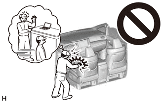
-
Be sure to read Precaution thoroughly before servicing.
-
except NR Series Engine:
-
for NR Series Engine:
- NOTICE:
-
After the ignition switch is turned off, there may be a waiting time before disconnecting the negative (-) auxiliary battery terminal.
- HINT:
-
When the cable is disconnected / reconnected to the auxiliary battery terminal, systems temporarily stop operating. However, each system has a function that completes learning the first time the system is used.
- ·
for HV Model:
Learning completes when vehicle is driven Effect/Inoperative Function When Necessary Procedures are not Performed Necessary Procedures Link Front Camera System Drive the vehicle straight ahead at 15 km/h (9 mph) or more for 1 second or more. (  202304,999999,_95,_139716,_0584193,RM1000000029F4C,)
·for Gasoline Model:
Learning completes when vehicle is driven Effect/Inoperative Function When Necessary Procedures are not Performed Necessary Procedures Link Stop and Start System Idle the engine for approximately 5 to 60 minutes or drive the vehicle until stop and start control is permitted ( 201906,999999,_51,_080774,_0393362,RM100000001HXHC,)
Pre-collision System Perform steering sensor zero point calibration ( 202304,999999,_95,_139716,_0601175,RM100000002BFOE,)
Lane Tracing Assist System Front Camera System Drive the vehicle straight ahead at 15 km/h (9 mph) or more for 1 second or more. ( 202304,999999,_95,_139716,_0584193,RM1000000029F4C,)
PROCEDURE

 1.REMOVE FRONT SEAT ASSEMBLY (for Manual Seat)
2.REMOVE FRONT SEAT ASSEMBLY (for Power Seat)
3.REMOVE REAR SEAT ASSEMBLY (for Fixed Seat Type)
4.REMOVE REAR SEAT ASSEMBLY (for Fold Down Seat Type)
67914
5.REMOVE FRONT DOOR SCUFF PLATE LH
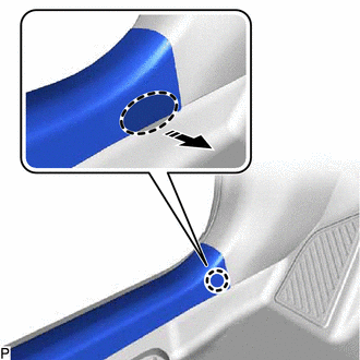

|
Place Hand Here |

|
Remove in this Direction |
Disengage the claw as shown in the illustration.
- HINT:
-
Use the same procedure for the front side and rear side.
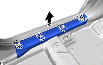
|
|
Remove in this Direction |
Disengage the 6 claws and 2 guides to remove the front door scuff plate LH as shown in the illustration.
62112A
6.REMOVE COWL SIDE TRIM SUB-ASSEMBLY LH
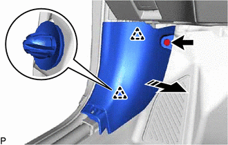
|
|
Remove in this Direction |
Remove the clip.
Disengage the 2 clips to remove the cowl side trim sub-assembly LH as shown in the illustration.
62312B
7.REMOVE FRONT DOOR OPENING TRIM WEATHERSTRIP LH
62212
8.REMOVE FRONT PILLAR GARNISH LH
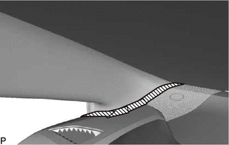

|
Protective Tape |
Apply protective tape around the front pillar garnish LH as shown in the illustration.
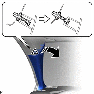
|
|
Remove in this Direction |
Pull the upper part of the front pillar garnish LH toward the inside of the cabin as shown in the illustration to disengage the front pillar garnish LH from the base of the front pillar garnish clip.
- HINT:
-
Let the front pillar garnish LH hang from the front pillar garnish clip.
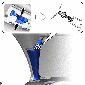
While pushing the tabs of the front pillar garnish clip as shown in the illustration, disengage it.
- HINT:
-
When the front pillar garnish clip cannot be disengaged easily:
- 1.
 0,0 0,0 false
Move in this Direction
While pushing the tab of the front pillar garnish clip shown in the illustration with your finger, move the front pillar garnish clip in the direction shown in the illustration.
2.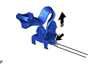 0,0 0,0 false
Pull in this Direction
While pulling the front pillar garnish clip as shown in the illustration, push the tab of the front pillar garnish clip shown in the illustration with a screwdriver and disengage the front pillar garnish clip.
|
|
Remove in this Direction |
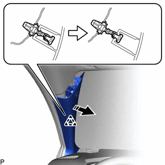
Disengage the front pillar garnish LH from the base of the front pillar garnish clip as shown in the illustration.
- HINT:
-
Let the front pillar garnish LH hang from the front pillar garnish clip.
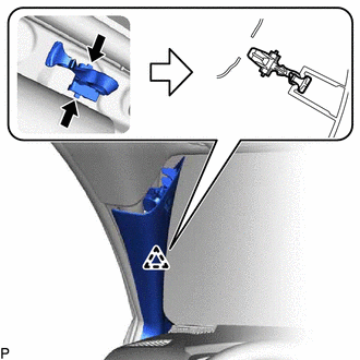
While pushing the tabs of the front pillar garnish clip as shown in the illustration, disengage it.
- HINT:
-
When the front pillar garnish clip cannot be disengaged easily:
- 1.
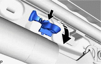 0,0 0,0 false
Move in this Direction
While pushing the tab of the front pillar garnish clip shown in the illustration with your finger, move the front pillar garnish clip in the direction shown in the illustration.
2.
0,0 0,0 false
Pull in this Direction
While pulling the front pillar garnish clip as shown in the illustration, push the tab of the front pillar garnish clip shown in the illustration with a screwdriver and disengage the front pillar garnish clip.
|
|
Remove in this Direction |
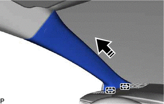
Disengage the 2 guides to remove the front pillar garnish LH as shown in the illustration.
Remove the 2 front pillar garnish clips from the front pillar garnish LH.
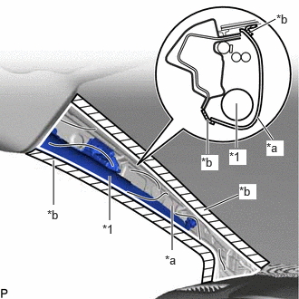
| *1 | Curtain Shield Airbag Assembly LH |
| *a | Protective Cover |
| *b | Adhesive Tape |
Protect the curtain shield airbag assembly LH.
Cover the curtain shield airbag assembly LH with a protective cover, such as a cloth, and secure the edges of the cover with tape as shown in the illustration.
- NOTICE:
-
Cover the curtain shield airbag assembly LH with a protective cover as soon as the front pillar garnish LH is removed.
67918A
9.REMOVE REAR DOOR SCUFF PLATE LH (for Gasoline Model)
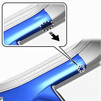
|
|
Place Hand Here |
|
|
Remove in this Direction |
Disengage the claw as shown in the illustration.
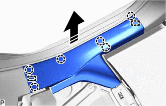
|
|
Remove in this Direction |
Disengage the 6 claws and 2 guides to remove the rear door scuff plate LH as shown in the illustration.
67918A
10.REMOVE REAR DOOR SCUFF PLATE LH (for HV Model)
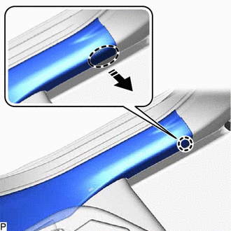
|
|
Place Hand Here |
|
|
Remove in this Direction |
Disengage the claw as shown in the illustration.
|
|
Remove in this Direction |
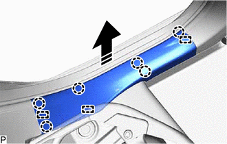
Disengage the 6 claws and 3 guides to remove the rear door scuff plate LH as shown in the illustration.
62332A
11.REMOVE REAR DOOR OPENING TRIM WEATHERSTRIP LH
73233
12.REMOVE LAP BELT OUTER ANCHOR COVER (for LH Side)
73220
13.DISCONNECT FRONT SEAT OUTER BELT ASSEMBLY LH
62414A
14.REMOVE CENTER PILLAR LOWER GARNISH LH
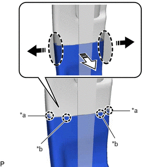
| *a | Claw (A) |
| *b | Claw (B) |
|
|
Place Hand Here |
|
|
Remove in this Direction (1) |

|
Remove in this Direction (2) |
Pull the center pillar lower garnish LH in the directions indicated by the arrows (1) shown in the illustration to disengage the 2 claws (A).
Pull the center pillar lower garnish LH in the direction indicated by the arrow (2) shown in the illustration to disengage the 2 claws (B).
|
|
Place Hand Here |
|
|
Remove in this Direction |
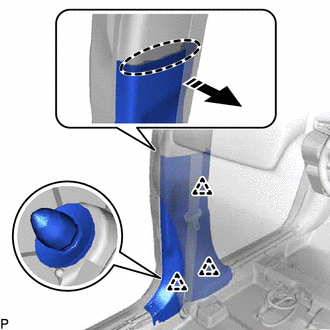
Disengage the 3 clips to remove the center pillar lower garnish LH as shown in the illustration.
62412B
15.REMOVE CENTER PILLAR UPPER GARNISH LH
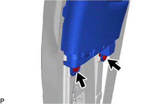
Using a clip remover, remove the 2 clips.
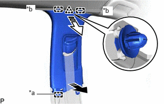
| *a | Guide (A) |
| *b | Guide (B) |
|
|
Remove in this Direction (1) |
|
|
Remove in this Direction (2) |
Pull the center pillar upper garnish LH in the directions indicated by the arrows (1) shown in the illustration to disengage the guide (A).
Pull the center pillar upper garnish LH in the direction indicated by the arrow (2) shown in the illustration to disengage the clip and 2 guides (B).
Pass the anchor of the front seat outer belt assembly LH through the center pillar upper garnish LH and remove the center pillar upper garnish LH.
67913
16.REMOVE FRONT DOOR SCUFF PLATE RH
- HINT:
-
Use the same procedure as for the LH side.
62111C
17.REMOVE COWL SIDE TRIM SUB-ASSEMBLY RH
- HINT:
-
Use the same procedure as for the LH side.
62311B
18.REMOVE FRONT DOOR OPENING TRIM WEATHERSTRIP RH
- HINT:
-
Use the same procedure as for the LH side.
62211
19.REMOVE FRONT PILLAR GARNISH RH
- HINT:
-
Use the same procedure as for the LH side.
67917A
20.REMOVE REAR DOOR SCUFF PLATE RH
- HINT:
-
Use the same procedure as for the LH side.
62331A
21.REMOVE REAR DOOR OPENING TRIM WEATHERSTRIP RH
- HINT:
-
Use the same procedure as for the LH side.
73233
22.REMOVE LAP BELT OUTER ANCHOR COVER (for RH Side)
- HINT:
-
Use the same procedure as for the LH side.
73210
23.DISCONNECT FRONT SEAT OUTER BELT ASSEMBLY RH
- HINT:
-
Use the same procedure as for the LH side.
62413A
24.REMOVE CENTER PILLAR LOWER GARNISH RH
- HINT:
-
Use the same procedure as for the LH side.
62411B
25.REMOVE CENTER PILLAR UPPER GARNISH RH
- HINT:
-
Use the same procedure as for the LH side.
76974F
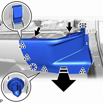
26.REMOVE REAR UNDER SIDE COVER LH (for HV Model)
|
|
Remove in this Direction |
Remove the 2 clips.
Disengage the claw, 4 clips and guide to remove the rear under side cover LH as shown in the illustration.
62552F
27.REMOVE REAR SEAT SIDE GARNISH LH
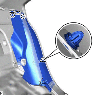
Disengage the clip, 2 claws and 2 guides.
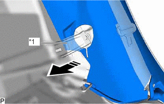
| *1 | Rear Seatback Hinge Sub-assembly LH |
|
|
Remove in this Direction |
Pass the rear seatback hinge sub-assembly LH through the rear seat side garnish LH as shown in the illustration and remove the rear seat side garnish LH.
62472A
28.REMOVE ROOF SIDE INNER GARNISH LH
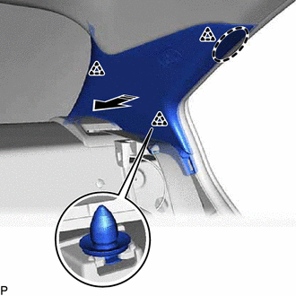
|
|
Place Hand Here |
|
|
Remove in this Direction |
Disengage the 3 clips as shown in the illustration.
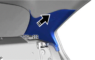
|
|
Remove in this Direction |
Disengage the 2 guides to remove the roof side inner garnish LH as shown in the illustration.
76973F
29.REMOVE REAR UNDER SIDE COVER RH (for HV Model)
- HINT:
-
Use the same procedure as for the LH side.
62551F
30.REMOVE REAR SEAT SIDE GARNISH RH
- HINT:
-
Use the same procedure as for the LH side.
62471A
31.REMOVE ROOF SIDE INNER GARNISH RH
- HINT:
-
Use the same procedure as for the LH side.
32.REMOVE INSTRUMENT PANEL SAFETY PAD SUB-ASSEMBLY
33.REMOVE TRANSMISSION FLOOR SHIFT ASSEMBLY (for CVT)
for K313: Click hereDrivetrain>K313 (CVT)>SHIFT LEVER>REMOVAL201906,999999,_52,_080728,_0392275,RM100000001HPBM,
for K320: Click hereDrivetrain>K320 / K321 (CVT)>SHIFT LEVER>REMOVAL202304,999999,_52,_096216,_0452232,RM1000000029R1V,
for K120: Click hereDrivetrain>K120 / K121 (CVT)>SHIFT LEVER>REMOVAL202304,999999,_52,_101162,_0469770,RM1000000029GYA,
34.REMOVE MAP LIGHT ASSEMBLY (for Bulb Type)
35.REMOVE MAP LIGHT ASSEMBLY (for LED Type)
81240
36.REMOVE NO. 1 ROOM LIGHT ASSEMBLY (for Bulb Type)
81360T
37.REMOVE SPOT LIGHT ASSEMBLY (for Bulb Type)
81360T
38.REMOVE SPOT LIGHT ASSEMBLY (for LED Type)
89941
39.REMOVE RAIN SENSOR (w/ Rain Sensor)
40.DISCONNECT TOLL COLLECTION ECU ASSEMBLY (w/ ETC for Type A)
When the toll collection ECU assembly is difficult to remove:
Disconnect the toll collection ECU assembly.
86466E
41.REMOVE NO. 2 FORWARD RECOGNITION COVER (w/ Pre-collision System)
for NR Series Engine:Click hereADAS / AD>ADVANCED DRIVER ASSISTANCE SYSTEM>FRONT CAMERA (for NR Series Engine)>REMOVAL202304,999999,_95,_139716,_0584840,RM1000000029I33_01_0022,
except NR Series Engine:Click hereADAS / AD>ADVANCED DRIVER ASSISTANCE SYSTEM>FRONT CAMERA (except NR Series Engine)>REMOVAL202304,999999,_95,_139716,_0584196,RM1000000029F5J_01_0022,
86466D
42.REMOVE NO. 1 FORWARD RECOGNITION COVER (w/ Pre-collision System)
for NR Series Engine:Click hereADAS / AD>ADVANCED DRIVER ASSISTANCE SYSTEM>FRONT CAMERA (for NR Series Engine)>REMOVAL202304,999999,_95,_139716,_0584840,RM1000000029I33_01_0023,
except NR Series Engine:Click hereADAS / AD>ADVANCED DRIVER ASSISTANCE SYSTEM>FRONT CAMERA (except NR Series Engine)>REMOVAL202304,999999,_95,_139716,_0584196,RM1000000029F5J_01_0023,
43.REMOVE COVER (w/ ETC for Type B)
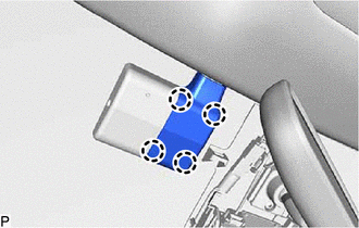
Disengage the 4 claws to remove the cover.
74610A
44.REMOVE ASSIST GRIP SUB-ASSEMBLY
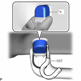
| *a | Cutout |
Insert SST into the cutout of the assist grip cover LH as shown in the illustration.
- SST
- 09813-00010
- NOTICE:
-
To prevent the assist grip sub-assembly from being damaged, make sure to insert SST straight into the cutout.
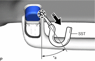
| *a | 30 to 45° |
|
|
Pull in this Direction |
Pull SST as shown in the illustration to disengage the claw.
- NOTICE:
-
To prevent the assist grip sub-assembly from being damaged, make sure to only pull SST as shown in the illustration.
- HINT:
- ·
Use the same procedure for the claw on the other side of the assist grip cover LH.
·Use the same procedure for the LH side and RH side.
Remove the assist grip cover LH.
- HINT:
-
Use the same procedure for the LH side and RH side.
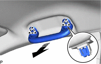
|
|
Remove in this Direction |
Disengage the 2 clips as shown in the illustration to remove the assist grip sub-assembly.
Remove the 2 clips from the vehicle body.
74630E
45.REMOVE REAR ASSIST GRIP ASSEMBLY LH
- HINT:
-
Use the same procedure as for the assist grip sub-assembly.
74620C
46.REMOVE REAR ASSIST GRIP ASSEMBLY RH
- HINT:
-
Use the same procedure as for the assist grip sub-assembly.
74325
47.REMOVE VISOR BRACKET COVER LH (w/ Cover)
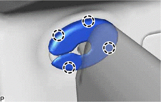
Disengage the 4 claws and remove the visor bracket cover LH.
74320
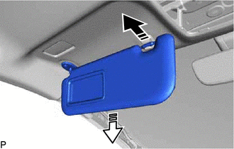
48.REMOVE VISOR ASSEMBLY LH
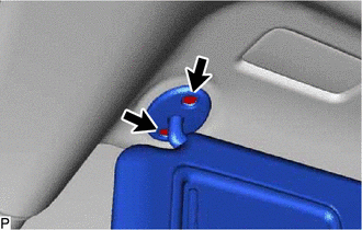
Remove the 2 screws.
|
|
Remove in this Direction (1) |
|
|
Remove in this Direction (2) |
Pull the visor assembly LH in the direction indicated by the arrow (1) shown in the illustration to disconnect it from the visor holder.
Pull the visor assembly LH in the direction indicated by the arrow (2) shown in the illustration to remove it.
74325
49.REMOVE VISOR BRACKET COVER RH (w/ Cover)
- HINT:
-
Use the same procedure as for the LH side.
74310
50.REMOVE VISOR ASSEMBLY RH
- HINT:
-
Use the same procedure as for the LH side.
51.REMOVE ROOF HEADLINING ASSEMBLY
for Windshield Glass Side with Connector:
Disconnect each connector.
for Front Pillar LH Side:
Remove the protective cover.
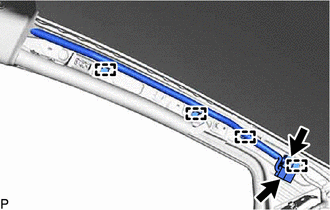
Using a clip remover, disengage the 4 clamps.
Disconnect each connector.
Install the protective cover.
for Front Pillar RH Side:
Remove the protective cover.
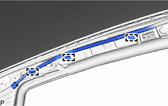
Using a clip remover, disengage the 3 clamps.
Install the protective cover.
for Rear Pillar RH Side:
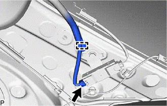
Disconnect the connector.
Disengage the clamp.

| *a | 45° |
|
|
Remove in this Direction (1) |
|
|
Remove in this Direction (2) |
Turn the visor holder approximately 45° and remove it as indicated by the arrows, in the order shown in the illustration.
- HINT:
-
Use the same procedure for the LH side and RH side.
for Roof Side (for Normal Roof):
Disengage the 2 claws to remove the base of each visor holder.
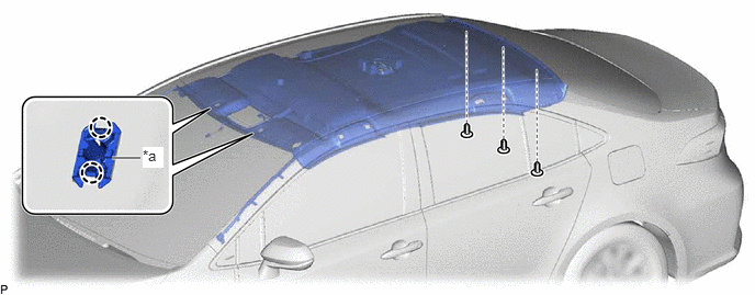
| *a | Base of Visor Holder | - | - |
Using a clip remover, remove the 3 clips.
for Roof Side (for Moon Roof):
Disconnect the connector.
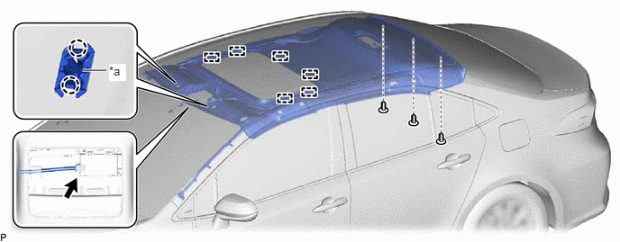
| *a | Base of Visor Holder | - | - |
Disengage the 2 claws to remove the base of each visor holder.
Using a clip remover, remove the 3 clips.
Disengage the 6 fasteners.
Remove the roof headlining assembly from the vehicle through the front door RH as shown in the illustration.
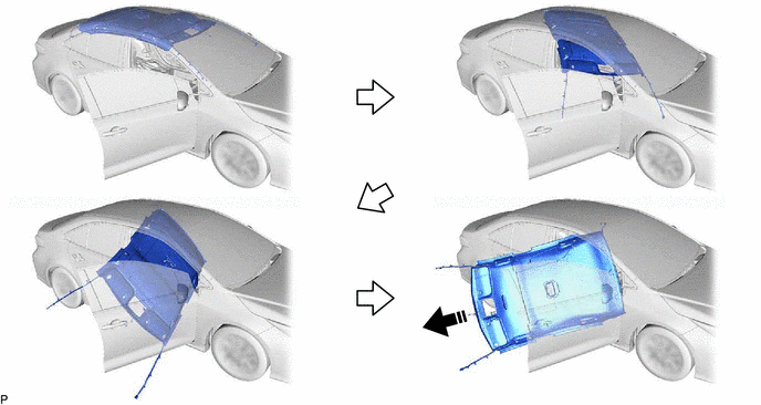
|
|
Remove in this Direction | - | - |
- NOTICE:
-
Do not damage the roof headlining assembly or vehicle interior.