STOP AND START STOP AND START SYSTEM Stop and Start Priority Control System
DESCRIPTION
In stop and start control status, there is normal status (Standard) and stop and start priority status (Extended).
Stop and start control status can be switched to the desired mode by pressing and holding the stop and start system cancel switch (combination switch assembly), or by operating the steering pad switch assembly, and the mode change is also shown on the multi-information display screen.
When the mode has been switched by pressing and holding the stop and start system cancel switch (combination switch assembly), a signal is sent directly from the stop and start system cancel switch (combination switch assembly) to the engine stop and start ECU.
When the steering pad switch assembly is used to select a control mode, a status change request signal is sent from the combination meter assembly to the engine stop and start ECU via CAN communication.
Cooperative control is performed by the air conditioning amplifier assembly and engine stop and start ECU based on the selected control mode.
When stop and start priority control (Extended) is selected, the operation time of stop and start control will be extended in order to improve fuel economy.
WIRING DIAGRAM
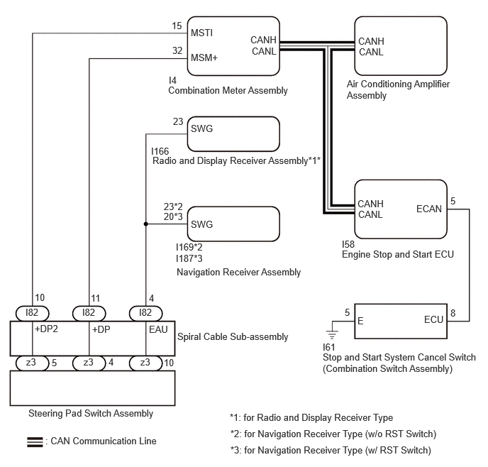
CAUTION / NOTICE / HINT
- NOTICE:
- ·
Before replacing the engine stop and start ECU, read the number of starter operations and write it into a new engine stop and start ECU.
·After replacing the engine stop and start ECU or air conditioning amplifier assembly, reset and perform learning of the air conditioning information in the engine stop and start ECU.
·After replacing the engine stop and start ECU or airbag sensor with ECU assembly, clear and calibrate the deceleration sensor zero point in the engine stop and start ECU.
·After replacing the engine stop and start ECU assembly, perform learning of the external backup boost converter (eco run vehicle converter assembly).
- HINT:
- ·
When stop and start priority control (Extended) is selected, the operation of the air conditioning system is limited. If the customer reports that the cooling effectiveness of the air conditioning system is poor, check the selected control mode. If stop and start priority control (Extended) is selected, cancel the control mode and check if the cooling effectiveness of the air conditioning system improves. If it improves, explain to the customer that the operation of the air conditioning system was limited by stop and start control.
·Depending on the vehicle conditions, the stop and start operation time may not change even if stop and start priority control (Extended) is selected.
PROCEDURE
Check the problem symptoms.
- HINT:
- ·
Check each symptom by checking the suspected areas in the table below.
·By using the GTS and entering the following menus, the selected mode can be confirmed.
Powertrain / Stop and Start / Data List / Stop & Start A/C Mode
- Result:
Problem Symptoms Trouble Area Proceed to Multi-information display screen does not change after pressing steering pad switch assembly ·Steering pad switch assembly
·Spiral cable sub-assembly
·Combination meter assembly
·Engine stop and start ECU
·Wire harness or connector (steering pad switch assembly - combination meter assembly, radio and display receiver assembly*1 or navigation receiver assembly*2)
·CAN communication system
A When the stop and start system cancel switch (combination switch assembly) is pressed and held, the status change interrupt display in the combination meter assembly is not displayed, and control does not change ·Stop and start system cancel switch (combination switch assembly)
·Engine stop and start ECU
·Wire harness or connector (stop and start system cancel switch (combination switch assembly) - engine stop and start ECU)
B Even though the stop and start system cancel switch (combination switch assembly) and steering pad switch assembly are operated, the multi-information display screen does not change, and control does not change ·Engine stop and start ECU
·CAN communication system
C Multi-information display screen changes without pressing steering pad switch assembly ·Steering pad switch assembly
·Spiral cable sub-assembly
·Wire harness or connector (steering pad switch assembly - combination meter assembly, radio and display receiver assembly*1 or navigation receiver assembly*2)
D The status change interrupt display in the combination meter assembly is not displayed, but control changes Combination meter assembly E The status change interrupt display in the combination meter assembly is displayed, but control does not change ·Air conditioning amplifier assembly
·CAN communication system
F Control mode returns to default mode after turning ignition switch ON Engine stop and start ECU G
*1: for Radio and Display Receiver Type
*2: for Navigation Receiver Type
A
B
C
D
E
F
G
Using the steering pad switch assembly, check that all functions other than "Stop & Start Settings" can be selected.
- Result:
Result Proceed to Only "Stop & Start Settings" cannot be selected A No function can be selected using the steering pad switch assembly B
A
B
Connect the GTS to the DLC3.
Turn the ignition switch to ON.
Turn the GTS on.
Perform a road test.
Enter the following menus: Powertrain / Stop and Start / Trouble Codes.
Read the DTCs.
- Powertrain > Stop and Start > Trouble Codes
- 50001 392
- Result:
Result Proceed to DTCs are not output A CAN DTCs are output B
A
B
Disconnect the spiral cable sub-assembly connector.
Disconnect the combination meter assembly connector.
Disconnect the radio and display receiver assembly connector. (for Radio and Display Receiver Type)
Disconnect the navigation receiver assembly connector. (for Navigation Receiver Type)
Measure the resistance according to the value(s) in the table below.
- Standard Resistance:
for Radio and Display Receiver Type Tester Connection Condition Specified Condition I82-11 (+DP) - I4-32 (MSM+) Always Below 1 Ω I82-10 (+DP2) - I4-15 (MSTI) Always Below 1 Ω I82-4 (EAU) - I166-23 (SWG) Always Below 1 Ω I82-11 (+DP) or I4-32 (MSM+) - Body ground and other terminals Always 10 kΩ or higher I82-10 (+DP2) or I4-15 (MSTI) - Body ground and other terminals Always 10 kΩ or higher I82-4 (EAU) or I166-23 (SWG) - Body ground and other terminals Always 10 kΩ or higher
for Navigation Receiver Type (w/ RST Switch) Tester Connection Condition Specified Condition I82-11 (+DP) - I4-32 (MSM+) Always Below 1 Ω I82-10 (+DP2) - I4-15 (MSTI) Always Below 1 Ω I82-4 (EAU) - I187-20 (SWG) Always Below 1 Ω I82-11 (+DP) or I4-32 (MSM+) - Body ground and other terminals Always 10 kΩ or higher I82-10 (+DP2) or I4-15 (MSTI) - Body ground and other terminals Always 10 kΩ or higher I82-4 (EAU) or I187-20 (SWG) - Body ground and other terminals Always 10 kΩ or higher
for Navigation Receiver Type (w/o RST Switch) Tester Connection Condition Specified Condition I82-11 (+DP) - I4-32 (MSM+) Always Below 1 Ω I82-10 (+DP2) - I4-15 (MSTI) Always Below 1 Ω I82-4 (EAU) - I169-23 (SWG) Always Below 1 Ω I82-11 (+DP) or I4-32 (MSM+) - Body ground and other terminals Always 10 kΩ or higher I82-10 (+DP2) or I4-15 (MSTI) - Body ground and other terminals Always 10 kΩ or higher I82-4 (EAU) or I169-23 (SWG) - Body ground and other terminals Always 10 kΩ or higher
- Result:
Proceed to OK NG
OK
NG
Inspect the spiral cable sub-assembly.
- Result:
Proceed to OK NG
OK
NG
Inspect the steering pad switch assembly.
- Result:
Proceed to OK NG
OK
NG
Connect the GTS to the DLC3.
Turn the ignition switch to ON.
Turn the GTS on.
Perform a road test.
Enter the following menus: Powertrain / Stop and Start / Trouble Codes.
Read the DTCs.
- Powertrain > Stop and Start > Trouble Codes
- 50001 392
- Result:
Result Proceed to DTCs are not output A CAN DTCs are output B
A
B
Connect the GTS to the DLC3.
Turn the ignition switch to ON.
Turn the GTS on.
Perform a road test.
Enter the following menus: Powertrain / Stop and Start / Trouble Codes.
Read the DTCs.
- Powertrain > Stop and Start > Trouble Codes
- 50001 392
- Result:
Result Proceed to DTCs are not output A DTCs are output B
A
B