STOP AND START STOP AND START SYSTEM Stop and Start Cancel Switch Circuit
DESCRIPTION
Stop and start control can be disabled by pressing the stop and start system cancel switch (combination switch assembly). The stop and start system cancel switch (combination switch assembly) is a momentary-type switch that switches between on and off when the switch is pressed. While stop and start control is disabled, the stop and start cancel indicator is illuminated to inform the driver.
WIRING DIAGRAM
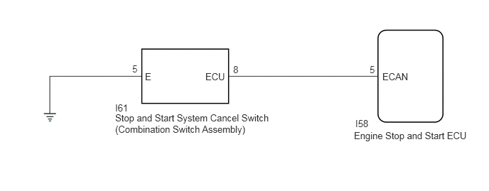
CAUTION / NOTICE / HINT
- NOTICE:
- ·
Before replacing the engine stop and start ECU assembly, read the number of starter operations and write it into a new engine stop and start ECU assembly.
·After replacing the engine stop and start ECU assembly or air conditioning amplifier assembly, reset and perform learning of the air conditioning information in the engine stop and start ECU assembly.
·After replacing the engine stop and start ECU assembly or airbag sensor with ECU assembly, clear and calibrate the deceleration sensor zero point in the engine stop and start ECU assembly.
·After replacing the engine stop and start ECU assembly, perform learning of the external backup boost converter (eco run vehicle converter assembly).
PROCEDURE
Connect the GTS to the DLC3.
Turn the ignition switch to ON.
Turn the GTS on.
Enter the following menus: Powertrain / Stop and Start / Data List / Stop&Start Cancel Switch.
- Powertrain > Stop and Start > Data List
-
Tester Display Stop&Start Cancel Switch - 50003 392 208
Read the value when the stop and start system cancel switch (combination switch assembly) is pressed.
- OK:
GTS Display Condition Normal Condition Stop&Start Cancel Switch Stop and start system cancel switch (combination switch assembly) is pressed ON Stop and start system cancel switch (combination switch assembly) is not pressed OFF
- Result:
Proceed to OK NG
OK
NG
Inspect the stop and start system cancel switch (combination switch assembly).
- Result:
Proceed to OK NG
OK
NG
Disconnect the stop and start system cancel switch (combination switch assembly) connector.
Measure the resistance according to the value(s) in the table below.
- Standard Resistance:
Tester Connection Condition Specified Condition I61-5 (E) - Body ground Always Below 1 Ω
- Result:
Proceed to OK NG
OK
NG
Disconnect the engine stop and start ECU connector.
Disconnect the stop and start system cancel switch (combination switch assembly) connector.
Measure the resistance according to the value(s) in the table below.
- Standard Resistance:
Tester Connection Condition Specified Condition I58-5 (ECAN) - I61-8 (ECU) Always Below 1 Ω I58-5 (ECAN) or I61-8 (ECU) - Body ground and other terminals Always 10 kΩ or higher
- Result:
Proceed to OK NG
OK
NG