7GR-FKS ENGINE MECHANICAL ENGINE ASSEMBLY REMOVAL
CAUTION / NOTICE / HINT
The necessary procedures (adjustment, calibration, initialization, or registration) that must be performed after parts are removed, installed, or replaced during the engine assembly removal/installation are shown below.
| Replaced Part or Performed Procedure | Necessary Procedure | Effect/Inoperative Function when Necessary Procedure not Performed | Link |
|---|---|---|---|
| Battery terminal is disconnected/reconnected | Memorize steering angle neutral point | Parking assist monitor system | ( 201902,202310,_56,_079315,_0385736,RM100000001GNRA,) 201902,202310,_56,_079315,_0385736,RM100000001GNRA,)
|
| Panoramic view monitor system | (201906,202310,_56,_079315,_0396274,RM100000001IGR3,)
|
||
| Replacement of ECM | Perform Vehicle Identification Number (VIN) or frame number registration | DTC P063051 is stored | (201902,999999,_51,_078720,_0381907,RM100000001G2WM,)
|
| ECU communication ID registration | Engine start function | See Service Bulletin for the registration method. | |
for RC60J:
Performing iMT installation information reset |
·
iMT system ·
DTCs are output |
(201902,999999,_52,_078740,_0383349,RM100000001GAF2,)
|
|
·
Engine assembly ·
Air leaks from intake system ·
Gas leaks from exhaust system |
Inspection after repair | ·
Poor idle, etc. ·
Engine start function, etc. |
(201902,999999,_51,_078720,_0381907,RM100000001G2VV,)
|
for AC60E:
Replacement of automatic transmission assembly |
Reset memory | ·
Large shift shock ·
Engine overruns |
(201902,999999,_52,_078741,_0385245,RM100000001GL7C,)
|
for AC60E:
Replacement of automatic transmission fluid |
ATF thermal degradation estimate reset | The value of the Data List item "ATF Thermal Degradation Estimate" is not estimated correctly | |
| Front wheel alignment adjustment | ·
Perform reset memory ·
Perform acceleration sensor zero point calibration and store system information memorization. |
·
VSC is disabled or malfunctions ·
DTCs are output ·
Slip indicator light illuminates ·
ABS warning light illuminates |
(201902,999999,_54,_078667,_0385049,RM100000001GK1P,)
|
| Suspension, tires, etc. | Television camera assembly optical axis (Back camera position setting) | Parking assist monitor system | (201902,202310,_56,_079315,_0385736,RM100000001GNRB,)
|
- HINT:
-
When the cable is disconnected / reconnected to the battery terminal, systems temporarily stop operating. However, each system has a function that completes learning the first time the system is used.
- ·
Learning completes when vehicle is driven
Effect/Inoperative when not Performed Necessary Procedures Link Lane control system Drive the vehicle straight ahead at 15 km/h (10 mph) or more for 1 second or more. ( 201902,999999,_58,_078886,_0382740,RM100000001G6XB,)
Pre-collision system
·Learning completes when vehicle is operated normally
Effect/Inoperative when not Performed Necessary Procedures Link Power slide door system Fully close the slide door by hand.
- HINT:
-
Initialization is not necessary if the above procedures are performed while the slide door is closed.
( 201902,202310,_59,_078503,_0381017,RM100000001FWXM,)
Air conditioning system After the ignition switch is turned to ON, the servo motor standard position is recognized. -
- CAUTION:
- ·
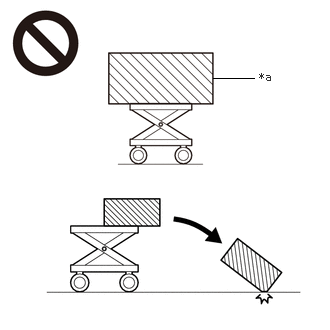 2.219,0.813 2.646,0.813 false 2.698,0.729 3.01,0.927 0.313,0.198 10 false *a
*a An Object Exceeding Weight Limit of Engine Lifter
The engine assembly with transmission is very heavy. Be sure to follow the procedure described in the repair manual, or the engine lifter may suddenly drop or the engine assembly may fall off the engine lifter.
·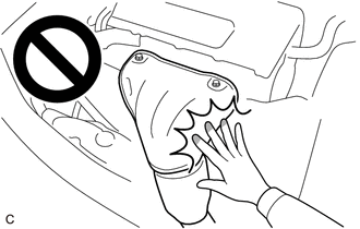
To prevent burns, do not touch the engine, exhaust manifold or other high temperature components while the engine is hot.
PROCEDURE

 1. PRECAUTION
- NOTICE:
-
After turning the ignition switch is turned off, there may be a waiting time before disconnecting the negative (-) battery terminal.
2.DISCHARGE FUEL SYSTEM PRESSURE
3.DISCONNECT CABLE FROM NEGATIVE BATTERY TERMINAL
4. ALIGN FRONT WHEELS FACING STRAIGHT AHEAD
5.SECURE STEERING WHEEL ASSEMBLY
6.REMOVE FRONT WHEELS
51406A
7.REMOVE NO. 2 ENGINE UNDER COVER SUB-ASSEMBLY (w/ No. 2 Engine Under Cover Sub-assembly)
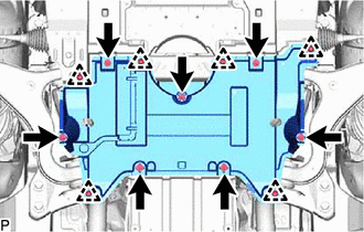
Remove the 6 clips, 7 bolts and No. 2 engine under cover sub-assembly.
52618
8.REMOVE LOWER FRONT BUMPER ABSORBER
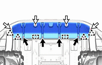

|
Bolt |

|
Screw |
Remove the 4 bolts, 4 screws and 4 clips.
Detach the 2 guides and remove the lower front bumper absorber.
51405A
9.REMOVE NO. 1 ENGINE UNDER COVER SUB-ASSEMBLY
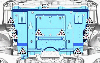
w/ No. 2 Engine Under Cover Sub-assembly:
Remove the 10 clips.
Detach the guide and remove the No. 1 engine under cover sub-assembly.
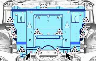
w/o No. 2 Engine Under Cover Sub-assembly:
Remove the 12 clips and 2 bolts.
Detach the guide and remove the No. 1 engine under cover sub-assembly.
51407A
10.REMOVE NO. 3 ENGINE UNDER COVER SUB-ASSEMBLY (w/ No. 3 Engine Under Cover Sub-assembly)
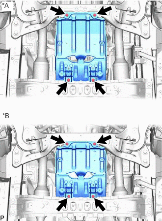
| *A | for Manual Transmission |
| *B | for Automatic Transmission |
Remove the 4 bolts and No. 3 engine under cover sub-assembly.
51773E
11.REMOVE STEP PLATE COVER RH (w/ Cover)
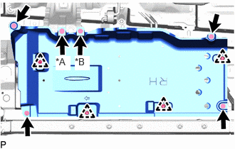
| *A | for Automatic Transmission |
| *B | for Manual Transmission |
Remove the 4 clips, 5 bolts and step plate cover RH.
12.DRAIN ENGINE OIL
13.DRAIN ENGINE COOLANT
14.DRAIN CLUTCH FLUID (for Manual Transmission)
15.DRAIN MANUAL TRANSMISSION OIL (for Manual Transmission)
16.DRAIN AUTOMATIC TRANSMISSION FLUID (for Automatic Transmission)
53106B
17.REMOVE RADIATOR COVER SUB-ASSEMBLY
18.RECOVER REFRIGERANT FROM REFRIGERATION SYSTEM (w/ Air Conditioning System)
85110
19.REMOVE WINDSHIELD WIPER MOTOR ASSEMBLY
47220D
20.DISCONNECT BRAKE MASTER CYLINDER RESERVOIR ASSEMBLY
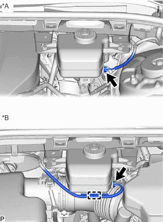
| *A | for LHD |
| *B | for RHD |
Disconnect the connector.
for RHD:
Detach the clamp and disconnect the wire harness from the brake master cylinder reservoir assembly.
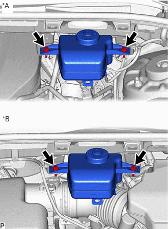
| *A | for LHD |
| *B | for RHD |
Remove the 2 nuts and disconnect the brake master cylinder reservoir assembly.
55738D
21.REMOVE NO. 2 HEATER AIR DUCT SPLASH SHIELD SEAL
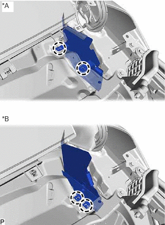
| *A | for LHD |
| *B | for RHD |
for LH Side:
Detach the 2 claws and remove the No. 2 heater air duct splash shield seal from the outer cowl top panel sub-assembly.
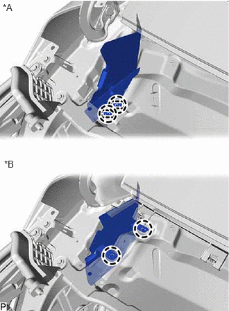
| *A | for LHD |
| *B | for RHD |
for RH Side:
Detach the 2 claws and remove the No. 2 heater air duct splash shield seal from the outer cowl top panel sub-assembly.
55701J
22.REMOVE OUTER COWL TOP PANEL SUB-ASSEMBLY
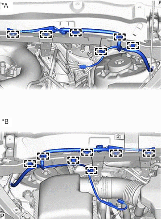
| *A | for LHD |
| *B | for RHD |
for LHD:
Detach the 6 clamps and disconnect the wire harness from the outer cowl top panel sub-assembly.
for RHD:
Detach the 7 clamps and disconnect the wire harness from the outer cowl top panel sub-assembly.
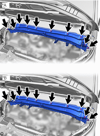
| *A | for LHD |
| *B | for RHD |
Remove the 10 bolts and outer cowl top panel sub-assembly.
11209
23.REMOVE V-BANK COVER SUB-ASSEMBLY (w/ Cover)
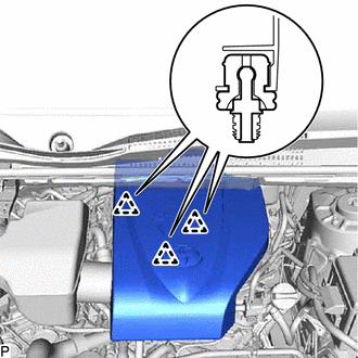
Raise the front of the V-bank cover to detach the 3 pins. Then remove the V-bank cover sub-assembly.
17751
24.REMOVE NO. 1 AIR CLEANER INLET
17881
25.REMOVE AIR CLEANER ASSEMBLY WITH AIR CLEANER HOSE
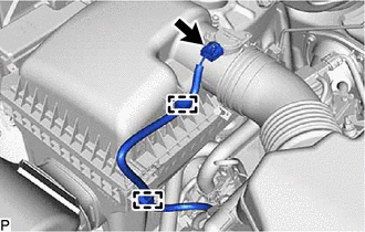
Disconnect the mass air flow meter sub-assembly connector.
Detach the 2 wire harness clamps.
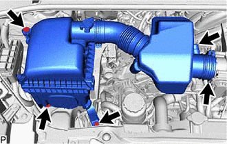
Slide the clamp and disconnect the No. 2 PCV hose from the No. 1 air cleaner hose.
Loosen the hose clamp.
Remove the 3 bolts and air cleaner assembly with air cleaner hose.
44360
26.DISCONNECT VANE PUMP OIL RESERVOIR ASSEMBLY
16470
27.REMOVE RADIATOR RESERVE TANK ASSEMBLY
16571C
28.REMOVE NO. 1 RADIATOR HOSE
16572D
29.REMOVE NO. 2 RADIATOR HOSE
32941
30.REMOVE NO. 1 OIL COOLER INLET HOSE AND NO. 1 OIL COOLER OUTLET HOSE (for Automatic Transmission)
16711
31.REMOVE FAN SHROUD
32.REMOVE FRONT BUMPER
82121
33.DISCONNECT ENGINE WIRE
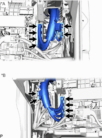
| *A | for LHD |
| *B | for RHD |
Disconnect the 4 connectors from the ECM.
Disconnect the 2 connectors from the instrument panel wire.
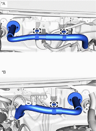
| *A | for LHD |
| *B | for RHD |
for LHD:
Detach the 2 clamps and grommet, and pull out the engine wire from the bracket.
for RHD:
Detach the clamp and grommet, and pull out the engine wire from the bracket.
34.DISCONNECT WIRE HARNESS
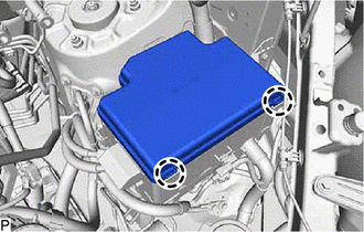
Detach the 2 claws and remove the upper No. 1 relay block cover from the No. 1 engine room relay block.
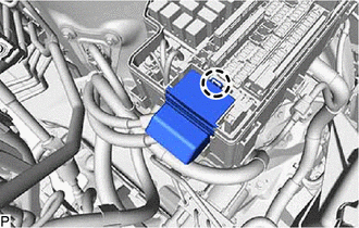
Detach the claw and remove the relay block cover from the No. 1 engine room relay block.
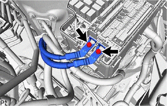
Remove the 2 bolts and disconnect the 2 wire harnesses from the No. 1 engine room relay block.
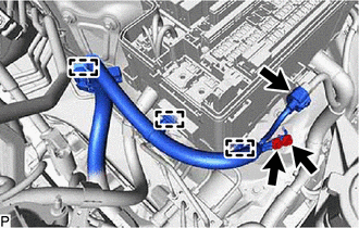
Remove the 2 bolts and disconnect the wire harness from the body.
Disconnect the connector.
Detach the 3 clamps and disconnect the wire harness from the No. 1 engine room relay block and bracket.
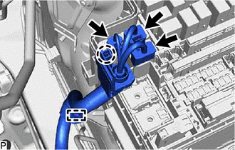
Detach the claw and 3 connectors from the No. 1 engine room relay block.
Detach the clamp and disconnect the wire harness from the bracket.
87245A
35.DISCONNECT HEATER WATER HOSE ASSEMBLY

Slide the 2 clamps and disconnect the 2 heater water hose assemblies from the water pipe.
23901
36.DISCONNECT FUEL TUBE SUB-ASSEMBLY
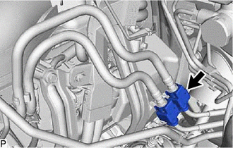
Remove the No. 2 fuel pipe clamp.
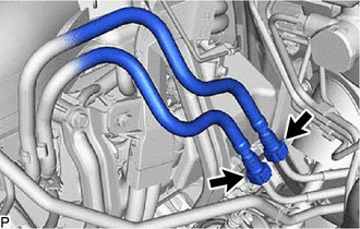
Disconnect the 2 fuel tube sub-assemblies.
37.DISCONNECT VACUUM HOSE ASSEMBLY
44310
38.DISCONNECT VANE PUMP ASSEMBLY
27020
39.REMOVE GENERATOR ASSEMBLY
88703
40.DISCONNECT DISCHARGE HOSE SUB-ASSEMBLY (w/ Air Conditioning System)
88704
41.DISCONNECT SUCTION HOSE SUB-ASSEMBLY (w/ Air Conditioning System)
88320
42.REMOVE COMPRESSOR ASSEMBLY WITH MAGNET CLUTCH (w/ Air Conditioning System)
16603K
43.REMOVE IDLER PULLEY SUB-ASSEMBLY (w/o Air Conditioning System)
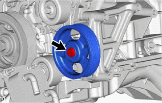
Remove the bolt, 2 plate washers and idler pulley sub-assembly.
16631D
44.REMOVE NO. 1 IDLER PULLEY BRACKET (w/o Air Conditioning System)
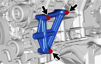
Remove the 3 bolts and No. 1 idler pulley bracket.
17346
45.DISCONNECT NO. 6 AIR INJECTION SYSTEM HOSE (w/ Secondary Air Injection System)
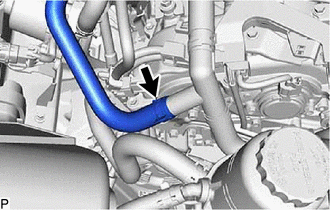
Slide the clip and disconnect the No. 6 air injection system hose from the air tube assembly.
17126
46.REMOVE NO. 2 SURGE TANK STAY
17125
47.REMOVE NO. 1 SURGE TANK STAY
22267A
48.REMOVE THROTTLE BODY BRACKET
17190
49.REMOVE INTAKE AIR SURGE TANK ASSEMBLY
17403
50.REMOVE FRONT NO. 3 EXHAUST PIPE SUB-ASSEMBLY
17410
51.REMOVE FRONT EXHAUST PIPE ASSEMBLY
17450B
52.REMOVE FRONT NO. 2 EXHAUST PIPE ASSEMBLY
17118
53.REMOVE MANIFOLD STAY
11409
54.REMOVE ENGINE OIL LEVEL DIPSTICK GUIDE
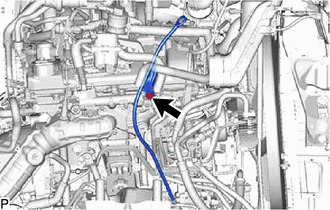
Remove the engine oil level dipstick.
Remove the bolt and engine oil level dipstick guide.
Remove the O-ring from the engine oil level dipstick guide.
17361N
55.REMOVE NO. 1 AIR TUBE (w/ Secondary Air Injection System)
17140
56.REMOVE EXHAUST MANIFOLD ASSEMBLY RH
17119
57.REMOVE NO. 2 MANIFOLD STAY
17362
58.REMOVE NO. 2 AIR TUBE (w/ Secondary Air Injection System)
17150
59.REMOVE EXHAUST MANIFOLD ASSEMBLY LH
51569A
60.REMOVE PROPELLER SHAFT GUARD
61.REMOVE PROPELLER SHAFT WITH CENTER BEARING ASSEMBLY
28192
62.REMOVE STARTER COVER
28100
63.REMOVE STARTER ASSEMBLY
11363A
64.REMOVE FLYWHEEL HOUSING SIDE COVER
65.DISCONNECT INTERMEDIATE SHAFT ASSEMBLY
89543
66.DISCONNECT FRONT SPEED SENSOR LH
89542
67.DISCONNECT FRONT SPEED SENSOR RH
- HINT:
-
Use the same procedure described for the LH side.
45047
68.DISCONNECT TIE ROD END SUB-ASSEMBLY LH
45046
69.DISCONNECT TIE ROD END SUB-ASSEMBLY RH
- HINT:
-
Use the same procedure described for the LH side.
70.DISCONNECT FRONT DISC BRAKE CALIPER ASSEMBLY LH
71.DISCONNECT FRONT DISC BRAKE CALIPER ASSEMBLY RH
- HINT:
-
Use the same procedure described for the LH side.
43512
72.REMOVE FRONT DISC
48069
73.DISCONNECT FRONT LOWER NO. 1 SUSPENSION ARM SUB-ASSEMBLY LH
48068
74.DISCONNECT FRONT LOWER NO. 1 SUSPENSION ARM SUB-ASSEMBLY RH
- HINT:
-
Use the same procedure described for the LH side.
48810
75.REMOVE FRONT STABILIZER LINK ASSEMBLY LH
48820B
76.REMOVE FRONT STABILIZER LINK ASSEMBLY RH
- HINT:
-
Use the same procedure described for the LH side.
77.REMOVE FRONT AXLE ASSEMBLY LH
78.REMOVE FRONT AXLE ASSEMBLY RH
- HINT:
-
Use the same procedure described for the LH side.
79.INSTALL ENGINE HANGER
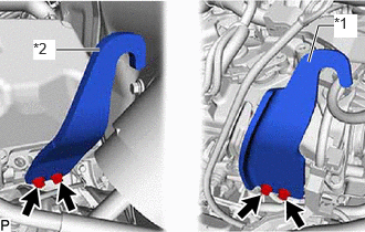
| *1 | No. 1 Engine Hanger |
| *2 | No. 2 Engine Hanger |
Install the 2 engine hangers with the 4 bolts as shown in the illustration.
- Torque:
- 33 N*m (337 kgf*cm, 24 ft.*lbf)
- HINT:
No. 1 Engine Hanger 12281-31070 No. 2 Engine Hanger 12282-31161 Bolt 91671-10825
80.REMOVE CLUTCH ACCUMULATOR HEAT INSULATOR SUB-ASSEMBLY (for Manual Transmission)
31349
81.REMOVE CLUTCH CABLE HEAT INSULATOR (for Manual Transmission)
31482D
82.REMOVE CLUTCH RELEASE CYLINDER TO ACCUMULATOR TUBE (for Manual Transmission)
31490
83.REMOVE CLUTCH ACCUMULATOR ASSEMBLY (for Manual Transmission)
31470
84.REMOVE CLUTCH RELEASE CYLINDER ASSEMBLY (for Manual Transmission)
31482
85.REMOVE CLUTCH RELEASE CYLINDER TO FLEXIBLE HOSE TUBE (for Manual Transmission)
33825
86.REMOVE TRANSMISSION CONTROL CABLE INSULATOR (for Manual Transmission)
33820B
87.DISCONNECT TRANSMISSION CONTROL CABLE ASSEMBLY (for Manual Transmission)
51446B
88.REMOVE NO. 2 ENGINE UNDER COVER BRACKET (for Manual Transmission)
58041C
89.REMOVE FRONT NO. 1 FLOOR HEAT INSULATOR SUB-ASSEMBLY (for Manual Transmission)
90.SUPPORT MANUAL TRANSMISSION ASSEMBLY (for Manual Transmission)
57209B
91.REMOVE REAR ENGINE MOUNTING MEMBER SUB-ASSEMBLY (for Manual Transmission)
12380
92.REMOVE REAR ENGINE MOUNTING INSULATOR ASSEMBLY (for Manual Transmission)
93.DISCONNECT WIRE HARNESS (for Manual Transmission)
88539C
94.DISCONNECT NO. 2 COOLER UNIT DRAIN HOSE (for Manual Transmission)
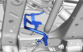
for LHD:
Detach the clamp and disconnect the No. 2 cooler unit drain hose.
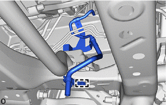
for RHD:
Detach the clamp and disconnect the No. 2 cooler unit drain hose.
95.REMOVE MANUAL TRANSMISSION ASSEMBLY (for Manual Transmission)
31210
96.REMOVE CLUTCH COVER ASSEMBLY (for Manual Transmission)
31250
97.REMOVE CLUTCH DISC ASSEMBLY (for Manual Transmission)
13405
98.REMOVE FLYWHEEL SUB-ASSEMBLY (for Manual Transmission)
53288B
99.REMOVE RADIATOR SUPPORT EXTENSION LH (for LHD)
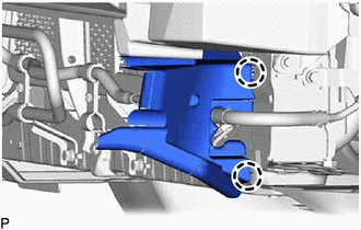
Detach the 2 claws and remove the radiator support extension LH.
53287B
100.REMOVE RADIATOR SUPPORT EXTENSION RH
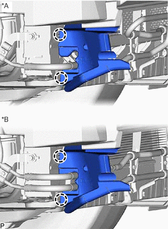
| *A | for LHD |
| *B | for RHD |
Detach the 2 claws and remove the radiator support extension RH.
44402
101.DISCONNECT NO. 1 POWER STEERING OIL COOLER SUB-ASSEMBLY
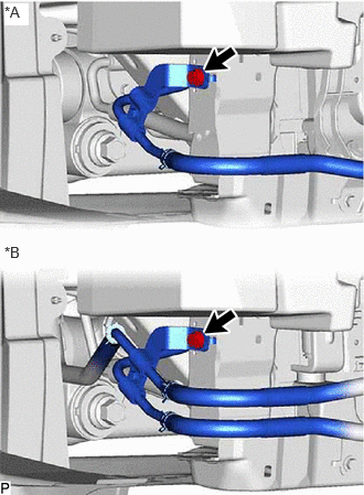
| *A | for LHD |
| *B | for RHD |
Remove the bolt and disconnect the return tube sub-assembly.
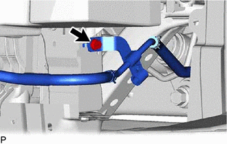
for LHD:
Remove the bolt and disconnect the return tube sub-assembly.
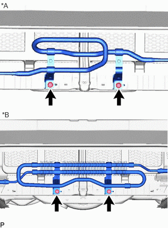
| *A | for Type A |
| *B | for Type B |
for LHD:
Remove the 2 bolts and disconnect the No. 1 power steering oil cooler sub-assembly.
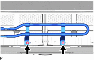
for RHD:
Remove the 2 bolts and disconnect the No. 1 power steering oil cooler sub-assembly.
51108C
102.REMOVE REAR SIDE RAIL REINFORCEMENT SUB-ASSEMBLY LH
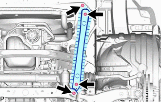
Remove the 4 bolts and rear side rail reinforcement sub-assembly LH.
51107D
103.REMOVE REAR SIDE RAIL REINFORCEMENT SUB-ASSEMBLY RH
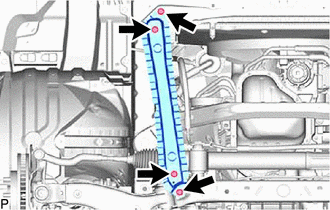
Remove the 4 bolts and rear side rail reinforcement sub-assembly RH.
104.REMOVE ENGINE ASSEMBLY (for Manual Transmission)
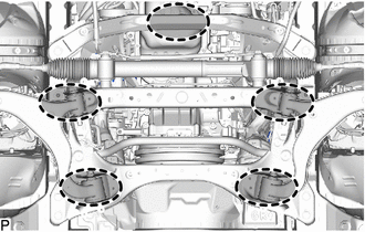

|
Place Wooden Block or Plate Attachments |
Set the engine on an engine lifter.
- NOTICE:
- ·
Place wooden blocks or plate lift attachments so that the engine is level.
·With the exception of installing the engine assembly to an engine stand or removing the engine assembly from an engine stand, do not perform any work on the engine while it is suspended, as doing so is dangerous.
·Never install attachments to the oil pan of the engine assembly as doing so may deform the oil pan.
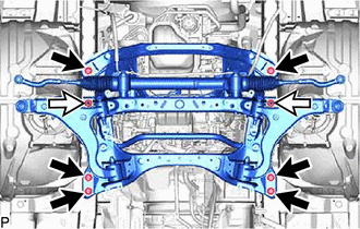
|
|
Bolt |
|
|
Nut |
Remove the 6 bolts and 2 nuts shown in the illustration.
Operate the engine lifter, then slowly remove the engine assembly from the vehicle.
- NOTICE:
- ·
Make sure the engine is clear of all wiring and hoses.
·While lowering the engine from the vehicle, do not allow it to contact the vehicle.
Attach an engine sling device and hang the engine with a chain block.
- NOTICE:
-
Pay attention to the angle of the sling device as the engine assembly or engine hangers may be damaged or deformed if the angle is incorrect.
58041C
105.REMOVE FRONT NO. 1 FLOOR HEAT INSULATOR SUB-ASSEMBLY (for Automatic Transmission)
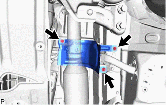
Remove the 3 bolts and front No. 1 floor heat insulator sub-assembly.
82122A
106.DISCONNECT NO. 2 ENGINE WIRE (for Automatic Transmission)
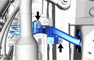
Remove the 2 bolts and disconnect the No. 2 engine wire from the vehicle body.
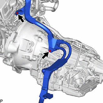
Remove the 2 bolts and disconnect the No. 2 engine wire from the engine assembly with automatic transmission assembly.
88539C
107.DISCONNECT NO. 2 COOLER UNIT DRAIN HOSE (for Automatic Transmission)
for LHD:
Detach the clamp and disconnect the No. 2 cooler unit drain hose.
for RHD:
Detach the clamp and disconnect the No. 2 cooler unit drain hose.
108.REMOVE ENGINE ASSEMBLY WITH AUTOMATIC TRANSMISSION ASSEMBLY (for Automatic Transmission)
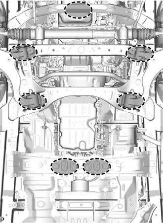
|
|
Place Wooden Block or Plate Attachments |
Set the engine on an engine lifter.
- NOTICE:
- ·
Place wooden blocks or plate lift attachments so that the engine is level.
·With the exception of installing the engine assembly to an engine stand or removing the engine assembly from an engine stand, do not perform any work on the engine while it is suspended, as doing so is dangerous.
·Never install attachments to the oil pan of the engine assembly or transmission as doing so may deform the oil pan.
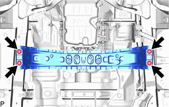
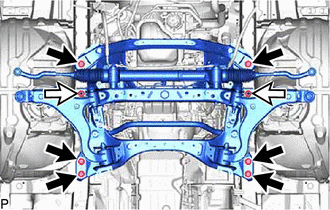
Remove the 4 bolts, and then separate the rear engine mounting member sub-assembly.
|
|
Bolt |
|
|
Nut |
Remove the 6 bolts and 2 nuts shown in the illustration.
Operate the engine lifter, then slowly remove the engine assembly with automatic transmission assembly from the vehicle.
- NOTICE:
- ·
Make sure the engine is clear of all wiring and hoses.
·While lowering the engine from the vehicle, do not allow it to contact the vehicle.
Attach an engine sling device and hang the engine with a chain block.
- NOTICE:
-
Pay attention to the angle of the sling device as the engine assembly or engine hangers may be damaged or deformed if the angle is incorrect.
32921
109.REMOVE NO. 1 OIL COOLER INLET TUBE AND NO. 1 OIL COOLER OUTLET TUBE (for Automatic Transmission)
110.DISCONNECT ENGINE WIRE (for Automatic Transmission)
111.REMOVE DRIVE PLATE AND TORQUE CONVERTER SETTING BOLT (for Automatic Transmission)
11361J
112.REMOVE FLYWHEEL HOUSING UNDER COVER (for Automatic Transmission)
57209B
113.REMOVE REAR ENGINE MOUNTING MEMBER SUB-ASSEMBLY (for Automatic Transmission)
12380
114.REMOVE REAR ENGINE MOUNTING INSULATOR ASSEMBLY (for Automatic Transmission)
35000
115.REMOVE AUTOMATIC TRANSMISSION ASSEMBLY (for Automatic Transmission)
32101
116.REMOVE DRIVE PLATE AND RING GEAR SUB-ASSEMBLY (for Automatic Transmission)
51100H
117.DISCONNECT FRONT FRAME ASSEMBLY
| *A | for LH Side |
| *B | for RH Side |
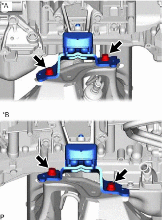
Remove the 4 bolts and disconnect the front frame assembly from the engine assembly.
12361E
118.REMOVE FRONT ENGINE MOUNTING INSULATOR
| *A | for LH Side |
| *B | for RH Side |
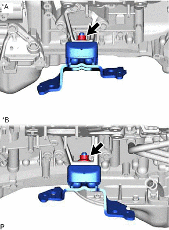
Remove the 2 nuts and 2 front engine mounting insulators from the front No. 1 engine mounting bracket RH and front No. 1 engine mounting bracket LH.
119.INSTALL ENGINE TO ENGINE STAND
Install the engine onto an engine stand with bolts.
- NOTICE:
- ·
Pay attention to the angle of the sling device as the engine assembly or engine hangers may be damaged or deformed if the angle is incorrect.
·With the exception of installing the engine assembly to an engine stand or removing the engine assembly from an engine stand, do not perform any work on the engine while it is suspended, as doing so is dangerous.
Remove the No. 1 engine hanger and No. 2 engine hanger with the 4 bolts.