WIPER / WASHER FRONT WIPER MOTOR REMOVAL
CAUTION / NOTICE / HINT
- HINT:
- ·
Use the same procedure for RHD and LHD vehicles.
·The procedure listed below is for LHD vehicles.
PROCEDURE

 85192
1.REMOVE WINDSHIELD WIPER ARM COVER
85192
1.REMOVE WINDSHIELD WIPER ARM COVER

|
Protective Tape |
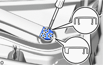
Using a thin-bladed screwdriver with its tip wrapped with protective tape, detach the claw and remove the windshield wiper arm cover.
- HINT:
-
Use the same procedure for the RH and LH sides.
2.REMOVE WINDSHIELD WIPER ARM AND BLADE ASSEMBLY LH
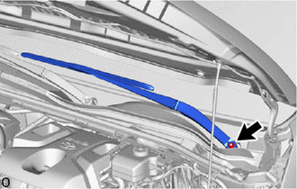
Remove the nut and the windshield wiper arm and blade assembly LH.
3.REMOVE WINDSHIELD WIPER ARM AND BLADE ASSEMBLY RH
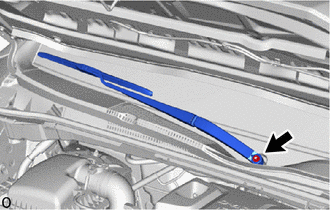
Remove the nut and the windshield wiper arm and blade assembly RH.
53867H
4.REMOVE FRONT FENDER TO COWL SIDE SEAL LH
|
|
Protective Tape |
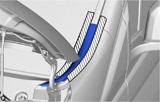
Put protective tape around the front fender to cowl side seal LH as shown in the illustration.
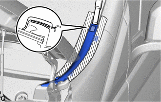
Using a scraper, etc., remove the double-sided tape.
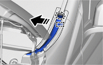

|
Remove in this Direction |
Place your hands at the position shown in the illustration and pull the front fender to cowl side seal LH toward the vehicle interior to detach the guide.
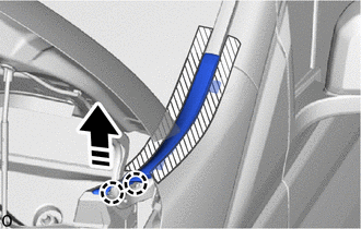
|
|
Remove in this Direction |
Detach the claw in the direction indicated by the arrow as shown in the illustration.
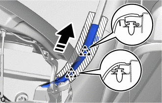
|
|
Remove in this Direction |
Detach the clip and remove the front fender to cowl side seal LH in the direction indicated by the arrow as shown in the illustration.
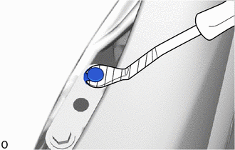
|
|
Protective Tape |
Using a clip remover with its tip wrapped with protective tape, detach the clip remaining on the vehicle.
53866J
5.REMOVE FRONT FENDER TO COWL SIDE SEAL RH
- HINT:
-
Use the same procedure described for the LH side.
53808G
6.REMOVE FENDER APRON MUDGUARD SEAL SUB-ASSEMBLY LH
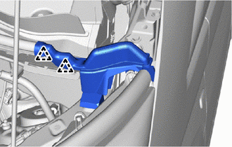
Detach the clip.
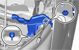
|
|
Protective Tape |
Using a screwdriver with its tip wrapped with protective tape, detach the claw.
Detach the clip and remove the fender apron mudguard seal sub-assembly LH.
53807G
7.REMOVE FENDER APRON MUDGUARD SEAL SUB-ASSEMBLY RH
- HINT:
-
Use the same procedure described for the LH side.
55708
8.REMOVE COWL TOP VENTILATOR LOUVER SUB-ASSEMBLY
- NOTICE:
-
To prevent damage to the windshield glass, remove any foreign matter (sand, dust, etc.) from around the contacting surfaces of the cowl top ventilator louver sub-assembly and windshield glass.
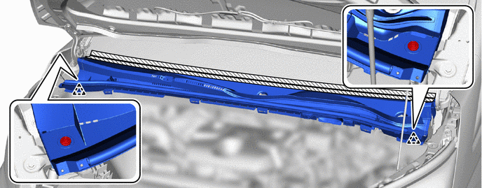
Apply protective tape between the cowl top ventilator louver sub-assembly and windshield glass sub-assembly.
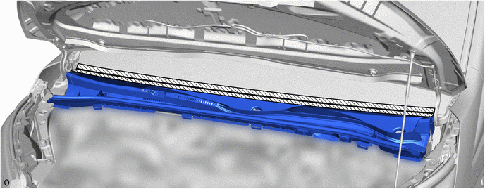
|
|
Protective Tape | - | - |
Remove the 2 clips.
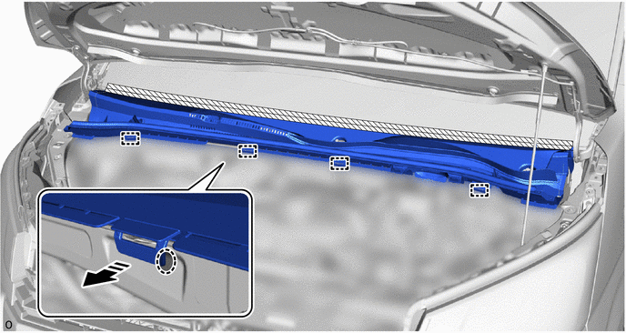
Detach the guide as shown in the illustration.
|
|
Remove in this Direction | - | - |
Insert a moulding remover at the starting position, as far as it can be inserted, to lift the cowl top ventilator louver sub-assembly and then hold it as shown in the illustration.
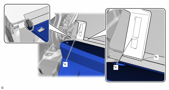
| *a | Starting Position:
Side of Cowl Top Ventilator Louver Sub-assembly and Moulding Remover Aligned |
*b | Inserted Far as Possible |

|
Place Hand Here | - | - |
| *a | Edge of Protective Tape |
|
|
Protective Tape |
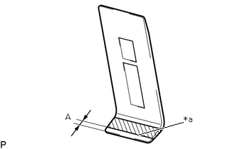
Apply protective tape to a moulding remover as shown in the illustration.
- Standard Dimension:
Area Dimension A 4.0 mm (0.157 in.)
Insert the moulding remover at the starting position until the edge of the protective tape is aligned with the cowl top ventilator louver sub-assembly as shown in the illustration.
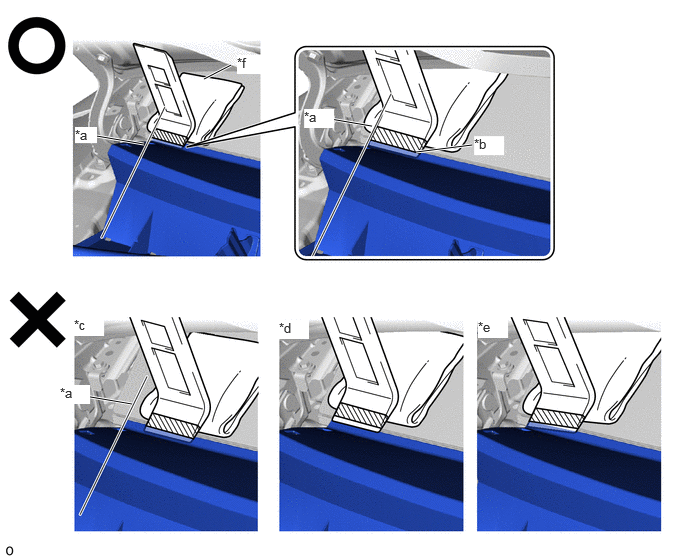
| *a | Starting Position:
Side of Cowl Top Ventilator Louver Sub-assembly and Moulding Remover Aligned |
*b | Inserted to Edge of Protective Tape |
| *c | Not Inserted at Starting Position | *d | Not Inserted to Edge of Protective Tape |
| *e | Not Inserted Straight | *f | Piece of Cloth or Equivalent |
|
|
Protective Tape | - | - |
- NOTICE:
- ·
To prevent damage to the windshield glass, set a piece of cloth between the moulding remover and windshield glass.
·Make sure to insert the moulding remover until the edge of protective tape is aligned with the cowl top ventilator louver sub-assembly, otherwise the cowl top ventilator louver sub-assembly may be deformed or damaged.
While pushing the moulding remover in the direction indicated by the arrow (A), pull the moulding remover in the direction indicated by the arrow (B) to detach the cowl top ventilator louver sub-assembly.
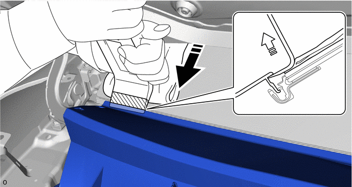
|
|
Push in this Direction (A) | 
|
Pull in this Direction (B) |
- NOTICE:
- ·
Make sure to repeat this procedure to disengage the entire cowl top ventilator louver sub-assembly.
·Make sure to perform this procedure while pushing the moulding remover in the direction indicated by the arrow (A), otherwise the cowl top ventilator louver sub-assembly may be deformed or damaged.
·Make sure not to pry the cowl top ventilator louver sub-assembly more than necessary to disengage it, otherwise it may be deformed or damaged.
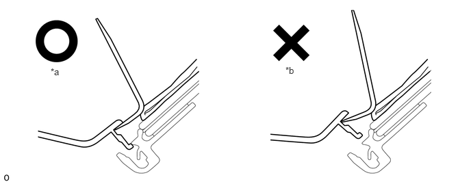 0.771,1.01 1.188,1.281 0.417,0.271 10 false *a 4.344,0.99 4.656,1.188 0.313,0.198 10 false *b
*a Pried Until Disengaged *b Pried Excessively
Using the moulding remover, repeatedly pry up the cowl top ventilator louver sub-assembly while gradually moving the moulding remover half of its width laterally toward the center of the vehicle and then repeat the procedure from the other side of the vehicle as shown in the illustration to detach the cowl top ventilator louver sub-assembly from the windshield glass.
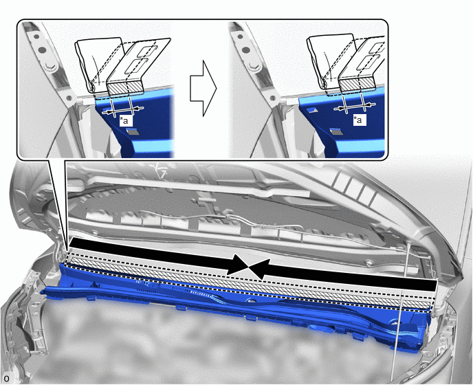
| *a | Half Width of Moulding Remover | - | - |

|
Order of Removal | - | - |
- NOTICE:
- ·
Make sure to move the moulding remover only half of its width laterally after prying up the cowl top ventilator louver sub-assembly, otherwise the cowl top ventilator louver sub-assembly may be damaged or deformed.
·Make sure not to lift up or pull the cowl top ventilator louver sub-assembly by hand before it is completely disengaged, otherwise it may be deformed or damaged.
While pulling up the front of the cowl top ventilator louver sub-assembly, remove the cowl top ventilator louver sub-assembly.
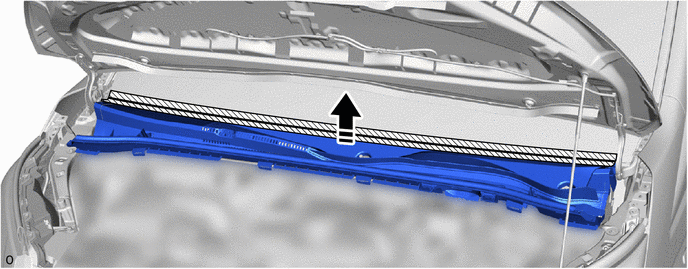
|
|
Remove in this Direction | - | - |
9.REMOVE WINDSHIELD WIPER MOTOR AND LINK ASSEMBLY
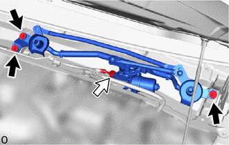
|
|
Bolt |

|
Connector |
Disconnect the connector.
Remove the 3 bolts.
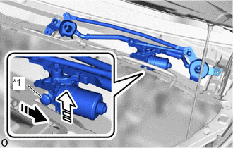
| *1 | Motor Grommet |
|
|
Remove in this Direction (1) |
|
|
Remove in this Direction (2) |
Detach the motor grommet as shown in the illustration.
Remove the windshield wiper motor and link assembly as shown in the illustration.
- NOTICE:
-
Do not damage the vehicle with the front wiper motor and link assembly.
85110
10.REMOVE WINDSHIELD WIPER MOTOR ASSEMBLY
- NOTICE:
-
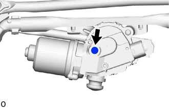
- ·
Do not touch the filter of waterproof cap.
·When removing the windshield wiper motor assembly, check the waterproof cap filter for any cracks or damage and that there is no grease on it.
·Do not reuse the windshield wiper motor assembly if it has been dropped or subjected to any strong impacts.
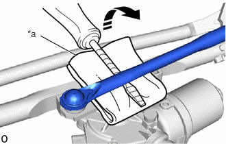
| *a | Cloth |
|
|
Protective Tape |
Using a screwdriver with its tip wrapped with protective tape, disconnect the No. 1 windshield wiper link rod from the windshield wiper motor crank pivot as shown in the illustration.
- NOTICE:
-
Wrap the wiper link assembly in cloth to prevent it from being damaged.
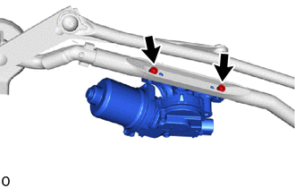
Using a T30 "TORX" socket wrench, remove the 2 "TORX" bolts and windshield wiper motor assembly.