HEATING / AIR CONDITIONING REAR AIR CONDITIONING UNIT INSTALLATION
PROCEDURE

 88566C
1.INSTALL NO. 3 COOLER AIR DUCT
88566C
1.INSTALL NO. 3 COOLER AIR DUCT
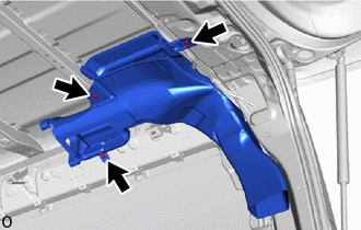
Install the No. 3 cooler air duct with the 3 clips.
62180E
2.INSTALL REAR CURTAIN SHIELD AIRBAG ASSEMBLY LH (w/ Curtain Shield Airbag)
87030
3.INSTALL AIR CONDITIONING BLOWER ASSEMBLY
Attach the guide to install the air conditioning blower assembly.
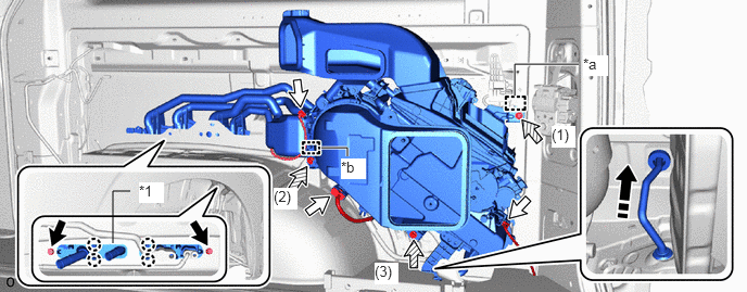
| *1 | Air Conditioning Tube And Accessory | - | - |
| *a | Guide | *b | Harness Clamp |

|
Bolt A | 
|
Connector |

|
Bolt B | 
|
Remove in this Direction |
Install the air conditioning blower assembly with the 3 bolts B and tighten the bolts in the order shown in the illustration.
- Torque:
- 9.8 N*m (100 kgf*cm, 87 in.*lbf)
Attach the harness clamp.
Connect each connector.
Connect the drain cooler hose to the grommet.
Attach the claw to connect the air conditioning tube and accessory assembly to the body.
Install the 2 bolts A.
- Torque:
- 9.8 N*m (100 kgf*cm, 87 in.*lbf)
88566B
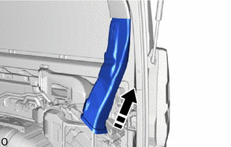
4.INSTALL NO. 2 COOLER AIR DUCT
|
|
Install in this Direction |
Install the No. 2 cooler air duct as shown in the illustration.

|
|
Move in this Direction |
Move the No. 2 cooler air duct as shown in the illustration.
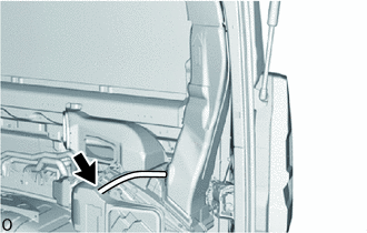
w/ Bypass Hose:
Install the hose.
88892Q
5.INSTALL COOLER PLATE
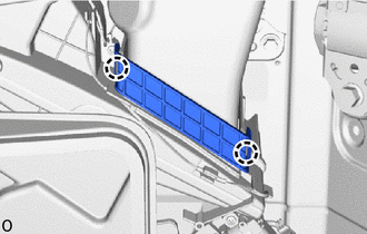
Attach the claw to install the cooler plate.
58793C
6.INSTALL NO. 1 JACK CARRIER BRACKET
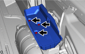
Install the No. 1 jack carrier bracket with the 3 bolts.
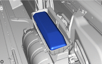
Install the tool bag.
62471D
7.INSTALL REAR UPPER PILLAR GARNISH RH
- HINT:
-
Use the same procedure described for the LH side.
62510M
8.INSTALL QUARTER TRIM PANEL ASSEMBLY RH
67871E
9.INSTALL NO. 1 SLIDE DOOR WEATHERSTRIP RH
67917C
10.INSTALL REAR DOOR SCUFF PLATE RH
73360D
11.INSTALL REAR SEAT OUTER BELT ASSEMBLY RH (w/ Seat Belt)
- HINT:
-
Use the same procedure described for the LH side.
73233D
12.INSTALL OUTER LAP BELT ANCHOR COVER (w/ Seat Belt)
67935
13.INSTALL BACK DOOR SCUFF PLATE
14.INSTALL REAR SEAT ASSEMBLY RH
for Manual Captain Seat:
for Power Captain Seat:
for 60/40 Split Seat Type 60 Side:
88716D
15.CONNECT COOLER REFRIGERANT LIQUID PIPE D
Remove the vinyl tape from the cooler refrigerant liquid pipe D.
Sufficiently apply compressor oil to a new O-ring and the fitting surface of the cooler refrigerant liquid pipe D.
- Compressor oil:
ND-OIL 8 or equivalent
Install the O-ring to the cooler refrigerant liquid pipe D.
- NOTICE:
-
Keep the O-rings and O-ring fitting surfaces free of foreign matter.
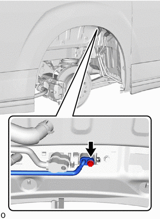
Connect the cooler refrigerant liquid pipe D with the bolt.
- Torque:
- 5.4 N*m (55 kgf*cm, 48 in.*lbf)
88727D
16.CONNECT COOLER REFRIGERANT SUCTION PIPE D
Remove the vinyl tape from the cooler refrigerant suction pipe D.
Sufficiently apply compressor oil to a new O-ring and the fitting surface of the cooler refrigerant suction pipe D.
- Compressor oil:
ND-OIL 8 or equivalent
Install the O-ring to the cooler refrigerant suction pipe D.
- NOTICE:
-
Keep the O-rings and O-ring fitting surfaces free of foreign matter.
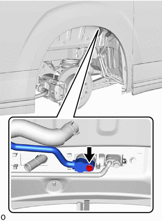
Connect the cooler refrigerant suction pipe D with the bolt.
- Torque:
- 5.4 N*m (55 kgf*cm, 48 in.*lbf)
87246G
17.CONNECT HEATER WATER HOSE OUTLET G
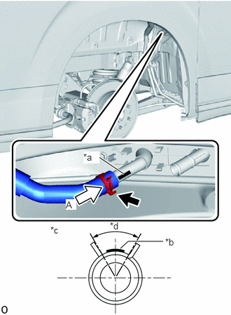
| *a | Marking (Yellow) |
| *b | Marking (Blue) |
| *c | View A |
| *d | Clip Installation Angle (60°) |
Align the rib of the air conditioning blower assembly with the marking (yellow). Connect the heater water hose outlet G and install the clip within the range shown in the illustration.
87246E
18.CONNECT HEATER WATER HOSE OUTLET E

| *a | Marking (Yellow) |
| *b | Marking (Orange) |
| *c | View A |
| *d | Clip Installation Angle (60°) |
Align the rib of the air conditioning blower assembly with the marking (yellow). Connect the heater water hose inlet E and install the clip within the range shown in the illustration.
65637B
19.INSTALL REAR WHEEL HOUSE LINER RH
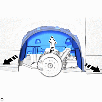
|
|
Install in this Direction (1) |

|
Install in this Direction (2) |
Bend the rear wheel house liner RH inward and attach it to the stud bolts to install the rear wheel house liner RH.
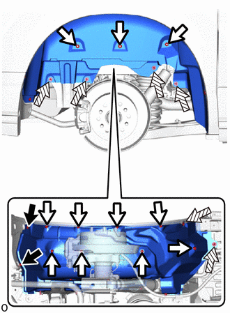
|
|
Screw |
|
|
Screw Clip |
|
|
Clip |
Rotate and install the 11 screw clips.
Install the 6 clips.
Install the 2 screws.
76907
20.INSTALL QUARTER PANEL MUDGUARD SUB-ASSEMBLY RH
- HINT:
-
Use the same procedure described for the LH side.
65631D
21.INSTALL REAR FRONT WHEEL HOUSE PLATE RH
- HINT:
-
Use the same procedure described for the LH side.
22.INSTALL WHEEL ASSEMBLY (Rear RH)
23.CONNECT CABLE TO NEGATIVE BATTERY TERMINAL (w/ Front Seat Side Airbag)
24. INITIALIZATION AFTER RECONNECTING BATTERY TERMINAL (w/ Front Seat Side Airbag)
- HINT:
-
When disconnecting and reconnecting the battery, there is an automatic learning function that completes learning when the respective system is used.
25.ADD ENGINE COOLANT
26.INSPECT FOR COOLANT LEAK
27. CHARGE AIR CONDITIONING SYSTEM WITH REFRIGERANT
28. WARM UP ENGINE
29.INSPECT FOR REFRIGERANT LEAK
30. INITIALIZATION SERVO MOTOR
31.PERFORM DIAGNOSTIC SYSTEM CHECK (w/ Front Seat Side Airbag)
32.CHECK SRS WARNING LIGHT (w/ Front Seat Side Airbag)