NAVIGATION / MULTI INFO DISPLAY NAVIGATION SYSTEM B15C2 Speed Signal Malfunction
DESCRIPTION
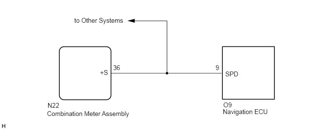
The navigation ECU receives a vehicle speed signal from the combination meter assembly and information from the navigation antenna assembly, and then adjusts the vehicle position on the map.
The navigation ECU stores this DTC when the difference between the speed information that the navigation antenna assembly receives and the SPD pulse received from the combination meter assembly becomes large.
- HINT:
- ·
A voltage of 12 V or 5 V is output from each ECU and then input to the combination meter assembly. The signal is changed to a pulse signal at the transistor in the combination meter assembly. Each ECU controls its respective system based on this pulse signal.
·If a short occurs in any of the ECUs or in the wire harness connected to an ECU, all systems in the following diagram will not operate normally.
| DTC No. | Detection Item | DTC Detection Condition | Trouble Area |
|---|---|---|---|
| B15C2 | Speed Signal Malfunction | A difference between the GPS speed and SPD pulse is detected | ·
Meter / gauge system ·
Navigation ECU ·
Radio and display receiver assembly ·
Harness or connector |
WIRING DIAGRAM
CAUTION / NOTICE / HINT
- NOTICE:
-
When replacing the radio and display receiver assembly or navigation ECU, always replace it with a new one. If a radio and display receiver assembly or navigation ECU which was installed to another vehicle is used, the following may occur:
- ·
A communication malfunction DTC may be stored.
·The radio and display receiver assembly or navigation ECU may not operate normally.
- HINT:
-
Depending on the parts that are replaced during vehicle inspection or maintenance, performing initialization, registration or calibration may be needed. Refer to Precaution for Navigation System.
PROCEDURE
Clear the DTCs.
- Body Electrical > Navigation System > Clear DTCs
- 50002 212
Recheck for DTCs and check that no DTCs are output.
- Body Electrical > Navigation System > Trouble Codes
- 50001 212
- OK:
No DTCs are output.
- Result:
Proceed to OK NG
OK
NG
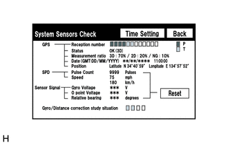
Enter the "System Sensors Check" screen. Refer to Check GPS & Vehicle Sensors in Operation Check.
While driving the vehicle, compare the value of "SPEED" indicator to the reading on the speedometer. Check if these readings are almost equal.
- HINT:
-
The combination meter assembly receives the vehicle speed signal from the skid control ECU via CAN communication. Therefore, perform the following procedure inspection referring to values in the Data List of the skid control ECU because it is the source of the vehicle speed signal.
- OK:
Vehicle speed displayed on the "System Sensors Check" screen is almost the same as the actual vehicle speed measured using the GTS.
- Result:
Proceed to OK NG
OK
NG
| *a | Component with harness connected
(Combination Meter Assembly) |
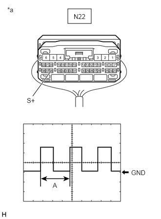
Check the output waveform.
Remove the combination meter assembly with the connector(s) still connected.
Connect an oscilloscope to terminal N22-36 (+S) and body ground.
Turn the ignition switch to ON.
Turn a wheel slowly.
Check the signal waveform according to the condition(s) in the table below.
| Item | Condition |
|---|---|
| Measurement terminal | N22-36 (+S) - Body ground |
| Tool setting | 5 V/DIV., 20 ms./DIV. |
| Vehicle condition | Wheel being rotated |
- OK:
The waveform is similar to that shown in the illustration.
- HINT:
-
When the system is functioning normally, one wheel revolution generates 4 pulses. As the vehicle speed increases, the width indicated by (A) in the illustration narrows.
- Result:
Proceed to OK NG
OK
NG
Disconnect the O9 navigation ECU connector.
Disconnect the N22 combination meter assembly connector.
Measure the resistance according to the value(s) in the table below.
- Standard Resistance:
Tester Connection Condition Specified Condition O9-9 (SPD) - N22-36 (+S) Always Below 1 Ω
- Result:
Proceed to OK NG
OK
NG
- Result:
Proceed to NEXT
NEXT
Clear the DTCs.
- Body Electrical > Navigation System > Clear DTCs
- 50002 212
Recheck for DTCs and check that no DTCs are output.
- Body Electrical > Navigation System > Trouble Codes
- 50001 212
- OK:
No DTCs are output.
- Result:
Proceed to OK NG
OK
NG