NAVIGATION / MULTI INFO DISPLAY NAVIGATION SYSTEM OPERATION CHECK
CHECK NAVIGATION SYSTEM NORMAL CONDITION
If the cause of a symptom is any of the following, the corresponding symptom is normal; it is not due to a malfunction.
| Symptom | Answer |
|---|---|
| A longer route than expected is chosen. | Depending on the road conditions, the navigation ECU may determine that a longer route is quicker. |
| Even when distance priority is high, the shortest route is not shown. | Some routes may not be advised due to safety concerns. |
| When the vehicle is put into motion immediately after the engine starts, the navigation system deviates from the correct position. | If the vehicle starts before the navigation system activates, the system may not react. |
| When driving on certain types of roads, especially new roads, the vehicle position deviates from the correct position. | When the vehicle is driving on new roads not available on the internal memory, the system attempts to match it to another nearby road, causing the position mark to deviate. |
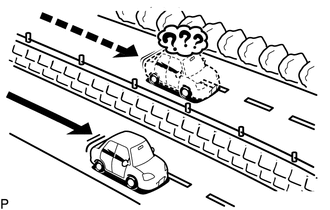
The following symptoms are not malfunctions, but are caused by errors inherent in the GPS, gyro sensor or navigation ECU.
The current position mark may be displayed on a nearby parallel road.
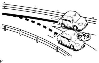
Immediately after a fork in the road, the current vehicle position mark may be displayed on the wrong road.
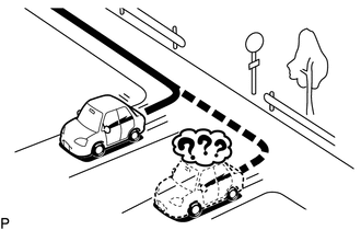
When the vehicle turns right or left at an intersection, the current vehicle position mark may be displayed on a nearby parallel road.
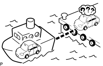
When the vehicle is carried, such as on a ferry, and the vehicle itself is not driving, the current vehicle position mark may be displayed in the position where the vehicle was until a measurement can be performed by the GPS.
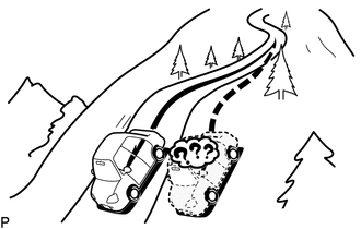
When the vehicle travels on a steep hill, the current vehicle position mark may deviate from the correct position.
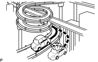
When the vehicle makes a continuous turn (e.g. 360, 720, 1080 degrees), the current vehicle position mark may deviate from the correct position.
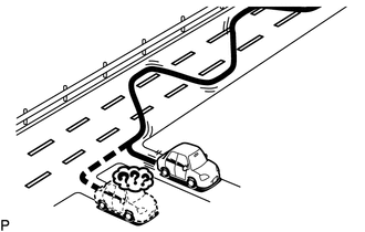
When the vehicle moves erratically, such as constant lane changes, the current vehicle position mark may deviate from the correct position.
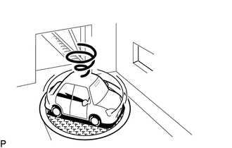
When the ignition switch is turned to ACC or ON and the vehicle is turned on a turntable before parking, the current vehicle position mark may not indicate the correct direction. The same will occur when the vehicle comes out of the parking garage.
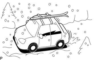
When the vehicle travels on a snowy road or a mountain path with tire chains installed or using a spare tire, the current vehicle position mark may deviate from the correct position.
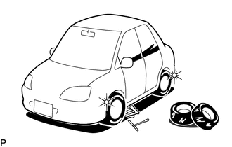
When the tires are changed, the current vehicle position mark may deviate from the correct position.
- HINT:
- ·
A change in tire diameter may cause a speed sensor error.
·Performing "tire change" in calibration mode will allow the system to correct the current vehicle position faster.
STORAGE CHECK (DCU STORAGE CHECK)
- NOTICE:
-
When replacing the radio and display receiver assembly, always replace it with a new one. If a radio and display receiver assembly which was installed to another vehicle is used, the following may occur:
- ·
A communication malfunction DTC may be stored.
·The radio and display receiver assembly may not operate normally.
- HINT:
- ·
Check the storage with it installed to the radio and display receiver assembly.
·Illustrations may differ from the actual vehicle screen depending on the device settings and options. Therefore, some detailed areas may not be shown exactly the same as on the actual vehicle screen.
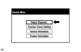
Select "Failure Diagnosis" from the "Service Menu" screen.
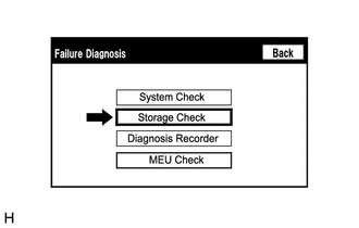
Select "Storage Check" from the "Failure Diagnosis" screen.
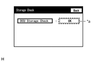
| *a | Result |
Storage Check
Select "DCU Storage Check" to start the DCU storage check.
Check the result displayed when the DCU storage check is complete.
| Display (Result) | Description |
|---|---|
| Checking | Check is in progress |
| OK | Radio and display receiver assembly storage is normal |
| NG | Radio and display receiver assembly storage is malfunctioning |
- HINT:
- ·
After selecting "DCU Storage Check", it may take a while for the result to be displayed.
·If the cabin temperature is -20°C (-4°F) or lower, or 65°C (149°F) or higher, the storage may not operate normally, and "NG" may be displayed. Make sure to perform troubleshooting with the cabin at an appropriate temperature.
·If "NG" is displayed even when the cabin temperature is appropriate, replace the radio and display receiver assembly with a new one.
STORAGE CHECK (MEU STORAGE CHECK)
- NOTICE:
-
When replacing the navigation ECU, always replace it with a new one. If a navigation ECU which was installed to another vehicle is used, the following may occur:
- ·
A communication malfunction DTC may be stored.
·The navigation ECU may not operate normally.
- HINT:
- ·
Check the storage with it installed to the navigation ECU.
·Illustrations may differ from the actual vehicle screen depending on the device settings and options. Therefore, some detailed areas may not be shown exactly the same as on the actual vehicle screen.
Select "Failure Diagnosis" from the "Service Menu" screen.
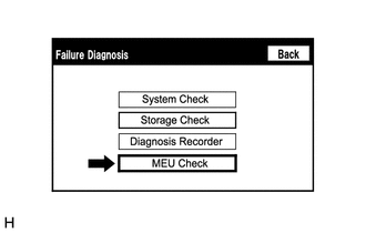
Select "MEU Check" from the "Failure Diagnosis" screen.
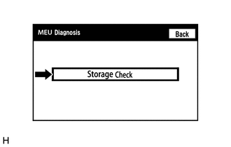
Select "Storage Check" from the "MEU Diagnosis" screen.
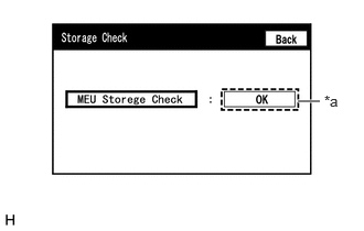
| *a | Result |
Storage Check
Select "MEU Storage Check" to start the MEU storage check.
Check the result displayed when the MEU storage check is complete.
| Display (Result) | Description |
|---|---|
| Checking | Check is in progress |
| OK | Navigation ECU storage is normal |
| NG | Navigation ECU storage is malfunctioning |
- HINT:
- ·
After selecting "MEU Storage Check", it may take a while for the result to be displayed.
·If the cabin temperature is -20°C (-4°F) or lower, or 65°C (149°F) or higher, the storage may not operate normally, and "NG" may be displayed. Make sure to perform troubleshooting with the cabin at an appropriate temperature.
·If "NG" is displayed even when the cabin temperature is appropriate, replace the navigation ECU with a new one.
CHECK PANEL & STEERING SWITCH
- HINT:
- ·
The radio and display receiver assembly panel switches and steering switches are checked in the following procedure.
·Illustrations may differ from the actual vehicle screen depending on the device settings and options. Therefore, some detailed areas may not be shown exactly the same as on the actual vehicle screen.
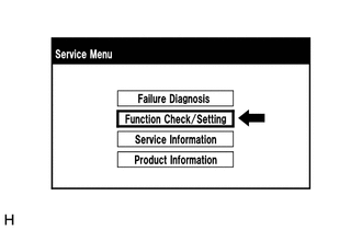
Select "Function Check/Setting" from the "Service Menu" screen.
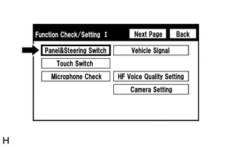
Select "Panel & Steering Switch" from the "Function Check/Setting I" screen.
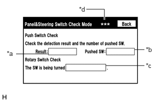
Panel & Steering Switch Check Mode
| Display | Content |
|---|---|
|
*: w/o AUX Function |
|
| *a: Switch condition | "Pushed" is displayed when any switch is pushed. |
| *b: Number of switches pushed | ·
Number of switches pushed at once is displayed. ·
If 3 switches are pushed at once, "3" is displayed. ·
If 4 or more switches are pushed at once, "More than 3" is displayed. |
| *c: Rotary switch direction | Direction of rotary switch is displayed. |
| *d: Communication method* | The steering pad switch assembly method of communication is displayed. |
Operate each switch and check that the switch conditions are correctly displayed.
- NOTICE:
-
Do not push any switch for 3 seconds or more as doing so may cancel diagnostic mode.
CHECK TOUCH SWITCH
- HINT:
- ·
The touch switches on the screen are checked in the following procedure.
·Illustrations may differ from the actual vehicle screen depending on the device settings and options. Therefore, some detailed areas may not be shown exactly the same as on the actual vehicle screen.
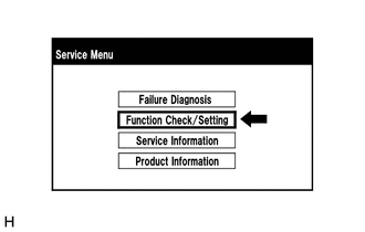
Select "Function Check/Setting" from the "Service Menu" screen.
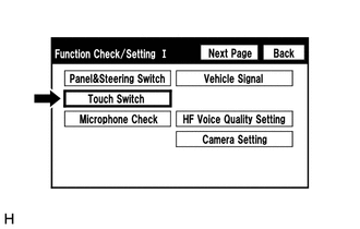
Select "Touch Switch" from the "Function Check/Setting I" screen.
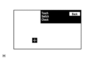
Touch Switch Check
Touch the display anywhere in the open area to perform the check when the "Touch Switch Check" screen is displayed.
- HINT:
- ·
A "+" mark is displayed where the display is touched.
·The "+" mark remains on the display even after your finger is removed.
CHECK MICROPHONE (INPUT TO RADIO AND DISPLAY RECEIVER ASSEMBLY)
- HINT:
- ·
The radio and display receiver assembly microphone and microphone input signal can be checked using the following procedures.
·Illustrations may differ from the actual vehicle screen depending on the device settings and options. Therefore, some detailed areas may not be shown exactly the same as on the actual vehicle screen.
Select "Function Check/Setting" from the "Service Menu" screen.
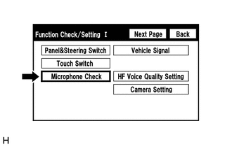
Select "Microphone Check" from the "Function Check/Setting I" screen.
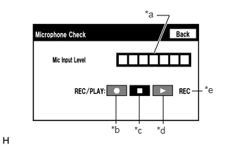
Microphone Check
| Display | Content |
|---|---|
|
*: w/ Recording Function |
|
| *a: Microphone input level meter | Monitors the microphone input level every 0.1 seconds and displays the results in 8 different levels. |
| *b: Recording switch* | Starts recording. |
| *c: Stop switch* | Stops recording and playing. |
| *d: Play switch* | Plays the recorded voice. |
| *e: Recording indicator* | Comes on while recording. |
When speaking into the microphone, check that the microphone input level meter changes according to the input level.
- HINT:
-
The microphone is active at all times when this screen is displayed.
Push the recording switch and perform voice recording. (w/ Recording Function)
- HINT:
- ·
Select the recording switch with the blower motor of the air conditioning system stopped. If an outlet of the air conditioning system is facing the microphone, noise may be recorded.
·While recording or playing, the switches other than the stop switch cannot be pushed.
·When no recording is present, the play switch cannot be pushed.
·Recording will stop after 5 seconds or when the stop switch is pushed.
Check that the recording indicator remains on while recording and that the recording can be played normally. (w/ Recording Function)
CHECK MICROPHONE (INPUT TO NAVIGATION ECU)
- HINT:
- ·
The navigation ECU microphone and microphone input signal can be checked using the following procedures.
·Illustrations may differ from the actual vehicle screen depending on the device settings and options. Therefore, some detailed areas may not be shown exactly the same as on the actual vehicle screen.
Select "Function Check/Setting" from the "Service Menu" screen.
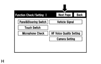
Select "Next page" from the "Function Check/Setting I" screen.
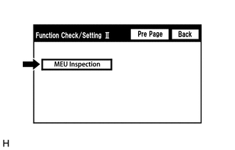
Select "MEU Inspection" from the "Function Check/Setting II" screen.
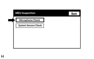
Select "Microphone Check" from the "MEU Inspection" screen.
Microphone Check
| Display | Content |
|---|---|
|
*: w/ Recording Function |
|
| *a: Microphone input level meter | Monitors the microphone input level every 0.1 seconds and displays the results in 8 different levels. |
| *b: Recording switch* | Starts recording. |
| *c: Stop switch* | Stops recording and playing. |
| *d: Play switch* | Plays the recorded voice. |
| *e: Recording indicator* | Comes on while recording. |
When speaking into the microphone, check that the microphone input level meter changes according to the input level.
- HINT:
-
The microphone is active at all times when this screen is displayed.
Push the recording switch and perform voice recording. (w/ Recording Function)
- HINT:
- ·
Select the recording switch with the blower motor of the air conditioning system stopped. If an outlet of the air conditioning system is facing the microphone, noise may be recorded.
·While recording or playing, the switches other than the stop switch cannot be pushed.
·When no recording is present, the play switch cannot be pushed.
·Recording will stop after 5 seconds or when the stop switch is pushed.
Check that the recording indicator remains on while recording and that the recording can be played normally. (w/ Recording Function)
CHECK GPS & VEHICLE SENSORS
- HINT:
- ·
GPS information, vehicle signals and sensor signals are checked in the following procedure.
·Illustrations may differ from the actual vehicle screen depending on the device settings and options. Therefore, some detailed areas may not be shown exactly the same as on the actual vehicle screen.
Select "Function Check/Setting" from the "Service Menu" screen.
Select "Next page" from the "Function Check/Setting I" screen.
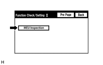
Select "MEU Inspection" from the "Function Check/Setting II" screen.
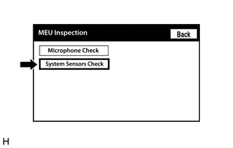
Select "System Sensors Check" from the "MEU Inspection" screen.
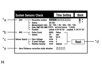
System Sensors Check
| Display | Content | ||
|---|---|---|---|
| Reception number | Displays reception condition of the satellites used to determine vehicle position | Blue: P (In use) | System is using GPS signal for location. |
| Yellow: T (Receiving) | System is tracking GPS signal for location. | ||
| No color: Not in use | System cannot receive GPS signal. (searching for GPS signal) | ||
| Status | Displays reception status of the satellites used to determine vehicle position | OK (3D) | 3-dimensional location method is being used. |
| OK (2D) | 2-dimensional location method is being used. | ||
| NG | Location data cannot be used. | ||
| error | Reception error has occurred. | ||
| - | Any other state. | ||
| Measurement ratio | Displays the ratio of satellites performing measurements | 3D | The ratio of satellites performing 3D positioning is displayed. |
| 2D | The ratio of satellites performing 2D positioning is displayed. | ||
| NG | The ratio of satellites not performing measurement is displayed. | ||
| Date | Date/time information obtained from GPS signals is displayed in Greenwich Mean Time (GMT). | ||
| Position | Latitude and longitude information on current position is displayed. | ||
| Display | Content |
|---|---|
| Pulse Count | Displays the accumulated number of input pulses beginning when this screen is displayed |
| Speed | Displays vehicle speed |
| Display | Content | Note |
|---|---|---|
| Gyro Voltage | Displays the output voltage of the gyro sensor | - |
| 0 point Voltage | Displays the zero-point voltage of the gyro sensor | - |
| Relative bearing | Displays the output angle of the gyro sensor | The amount of change in bearing angle (degrees) after the system sensor check screen is displayed (clockwise: "+", counterclockwise: "-"). |
| Display | Content |
|---|---|
| Reset | When this switch is pressed and held for 3 seconds or more, the values for the display items of SPD signal and gyro sensor signal are reset and display "0". |
| Display | Content |
|---|---|
| Gyro/Distance correction study situation | Displays learning status of Gyro/Distance correction |
| Display | Content |
|---|---|
| Gyro/Distance correction study situation | Not available |
When the "System Sensors Check" screen is displayed, check all the sensor signals.
- HINT:
-
This screen is updated once per second.
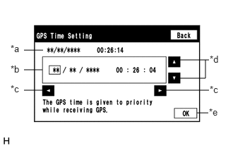
GPS Time Setting (w/ GPS Time Setting Function)
| Display | Content |
|---|---|
| *a: Time display | Displays the date and time in the device. |
| *b: Date and time setting screen | Setting is possible only when GPS signals are not being received. |
| *c: Cursor movement switch | Moves the cursor on the date and time setting screen to the right and left. |
| *d: Adjustment switch | Adjusts values of items selected by the cursor. |
| *e: OK switch | Selecting this switch after setting the date and time updates the date and time in the device (only when GPS signals are not being received). |
When GPS signals are not being received, the date and time in the device can be adjusted.
- HINT:
-
Time setting is possible only when GPS signals are not being received. When the navigation system is receiving GPS signals, priority is given to displaying the time and date received via GPS.
CHECK VEHICLE SIGNAL
- HINT:
- ·
Vehicle signals received by the radio and display receiver assembly are checked in the following procedure.
·Illustrations may differ from the actual vehicle screen depending on the device settings and options. Therefore, some detailed areas may not be shown exactly the same as on the actual vehicle screen.
Select "Function Check/Setting" from the "Service Menu" screen.
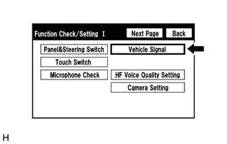
Select "Vehicle Signal" from the "Function Check/Setting I" screen.
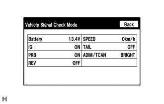
Vehicle Signal Check Mode
| Display | Content |
|---|---|
| Battery | Battery voltage is displayed. |
| IG | Ignition switch ON/OFF state is displayed. |
| PKB | Parking brake ON/OFF state is displayed. |
| REV | Reverse signal ON/OFF state is displayed. |
| SPEED | Vehicle speed is displayed in km/h. |
| TAIL | Tail signal (light control switch) ON/OFF state is displayed. |
| ADIM/TCAN | Brightness state DIM (with) / BRIGHT (without) is displayed. |
- HINT:
- ·
Only items for which signals have been received will be displayed.
·This screen displays vehicle signals input to the radio and display receiver assembly.
·This screen is updated once per second.
When the "Vehicle Signal Check Mode" screen is displayed, check all the vehicle signal conditions.
CHECK HANDS-FREE VOICE QUALITY AND VOLUME SETTING
- NOTICE:
- ·
These settings are adjusted separately for each registered cellular phone.
·If a cellular phone has not been registered, the settings cannot be adjusted.
- HINT:
- ·
The hands-free voice quality of a "Bluetooth" compatible phone can be adjusted using the following procedure.
·Illustrations may differ from the actual vehicle screen depending on the device settings and options. Therefore, some detailed areas may not be shown exactly the same as on the actual vehicle screen.
Select "Function Check/Setting" from the "Service Menu" screen.
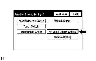
Select "HF Voice Quality Setting" from the "Function Check/Setting I" screen.
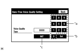
| *a | Numeric Keypad |
| *b | Setting Button |
| *c | Reset Button |
Hands-Free Voice Quality Setting
If necessary, refer to the table below to adjust the voice quality type with the numeric keypad.
When adjusting the settings, use the numeric keypad on the screen to input the voice quality type according to the table.
| Parameter | Target Phenomenon | Voice Quality Type | Positive Effect of Changing Voice Quality | Negative Effect of Changing Voice Quality |
|---|---|---|---|---|
| A
(Noise) |
The other party hears background noise when listening to your voice. | 1000 | The amount of background noise the other party hears when listening to your voice is reduced. | The volume of voice the other party hears when listening to your voice may temporarily drop. |
| B
(Noise) |
The other party hears a lot of background noise when listening to your voice. | 2000 | The amount of background noise the other party hears when listening to your voice is sharply reduced. | The volume of voice the other party hears when listening to your voice may temporarily drop. |
| C
(Echo) |
The other party hears weak echoes. | 0100 | The amount of echo is reduced (low level). | Sound quality of the other party deteriorates (low level). |
| D
(Echo) |
The other party hears strong echoes. | 0200 | The amount of echo is reduced (high level). | Sound quality of the other party deteriorates (high level). |
| Parameter | Target Phenomenon | Voice Quality Type | Positive Effect of Changing Voice Quality | Negative Effect of Changing Voice Quality |
|---|---|---|---|---|
| A+C | The other party hears background noise and weak echoes when listening to your voice. | 1100 | ·
The amount of background noise the other party hears when listening to your voice is reduced. ·
The amount of echo is reduced (low level). |
·
The volume of voice may drop temporarily. ·
Sound quality of the other party deteriorates (low level). |
| A+D | The other party hears background noise and strong echoes when listening to your voice. | 1200 | ·
The amount of background noise the other party hears when listening to your voice is reduced. ·
The amount of echo is reduced (high level). |
·
The volume of voice may drop temporarily. ·
Sound quality of the other party deteriorates (high level). |
| B+C | The other party hears a lot of background noise and weak echoes when listening to your voice. | 2100 | ·
The amount of background noise the other party hears when listening to your voice is sharply reduced. ·
The amount of echo is reduced (low level). |
·
The volume of voice may drop temporarily. ·
Sound quality of the other party deteriorates (low level). |
| B+D | The other party hears a lot of background noise and strong echoes when listening to your voice. | 2200 | ·
The amount of background noise the other party hears when listening to your voice is sharply reduced. ·
The amount of echo is reduced (high level). |
·
The volume of voice may drop temporarily. ·
Sound quality of the other party deteriorates (high level). |
- HINT:
- ·
The default value is "0000".
·Settings will be applied when the setting button is selected.
·If voice quality type values that are not in the table are input, the setting will not be applied and a positive effect may not be gained.
·If the quality of phone calls decreases due to the changed settings, return the settings to "0000" by selecting "INIT".
CHECK DAB RECEPTION
- HINT:
- ·
The reception condition of Digital Audio Broadcast (DAB) can be checked.
·Illustrations may differ from the actual vehicle screen depending on the device settings and options. Therefore, some detailed areas may not be shown exactly the same as on the actual vehicle screen.
Select "Function Check/Setting" from the "Service Menu" screen.
Select "Next Page" from the "Function Check/Setting I" screen.
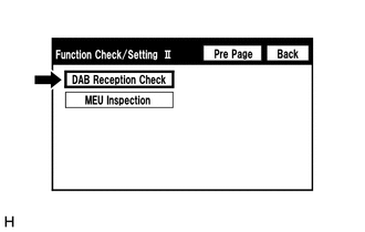
Select "DAB Reception Check" from the "Function Check/Setting II" screen.
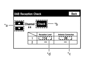
DAB Reception Check
| Display | Content |
|---|---|
| Up or down button | Enables the channel to be changed to the one to be checked. |
| Display | Condition | Content |
|---|---|---|
| Check | Before/after check | Starts checking |
| STOP | During check | Stops checking |
| Display | Content |
|---|---|
| OK | Connected properly |
| NG | Not connected properly |
| - | Not equipped with DAB antenna |
| Display | Content |
|---|---|
| Black | Good reception |
| Red | Poor reception |
| - | Not equipped with DAB antenna |
Select "Check" to start the DAB reception check.
Check the results displayed when the DAB reception check is completed.
CLEAR PASSWORD OF EXPORT/IMPORT MEMORY POINT FUNCTION
- HINT:
- ·
This function allows the initialization of a password which was set on the navigation ECU when exporting/importing memory points.
·Illustrations may differ from the actual vehicle screen depending on the device settings and options. Therefore, some detailed areas may not be shown exactly the same as on the actual vehicle screen.
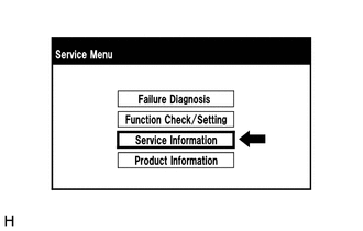
Select "Service Information" from the "Service Menu" screen.
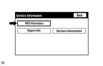
Select "MEU Information" from the "Service Information" screen.
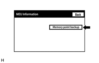
Select "Memory point backup" from the "MEU Information" screen.
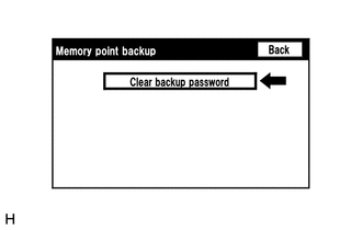
Clear backup password
- HINT:
-
Depending on the manufacturer, some component names and versions will be displayed differently.
Select "Clear backup password" from the "Memory point backup" screen.
CHECK SPEAKER
- HINT:
- ·
This function is used when checking the speaker wiring and whether the speakers are functioning properly.
·Illustrations may differ from the actual vehicle screen depending on the device settings and options. Therefore, some detailed areas may not be shown exactly the same as on the actual vehicle screen.
Turn radio and display receiver assembly on and play any audio source.
- HINT:
- ·
This audio source will be used for the speaker check.
·The "SPCheck ON" button is grayed out and cannot be pressed when the audio source is off.
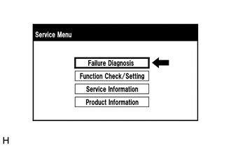
Select "Failure Diagnosis" from the "Service Menu" screen.
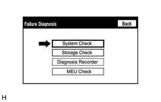
Select "System Check" from the "Failure Diagnosis" screen.
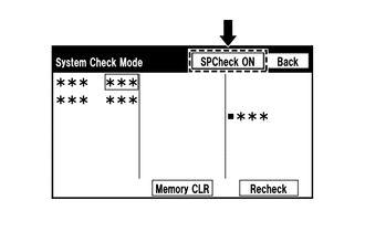
Select "SPCheck ON" from the "System Check Mode" screen.
Check the speaker wiring and check that the speakers are functioning properly.
- HINT:
- ·
Check that each speaker outputs sound from the selected audio source properly.
·"SPCheck OFF" is displayed during the speaker check.
·Sound can be heard from the speakers around the vehicle in order beginning from the speaker on the driver side.
·More than one speaker may sound simultaneously depending on the speaker wiring.
·The sounding order during speaker check cannot be adjusted.
Sound stops when any of the following conditions are met:
"SPCheck OFF" is selected.
The ignition switch is turned off.
Diagnostic mode is turned off.
The screen is changed to another screen.
Audio mode is turned off.
CHECK SOFTWARE ERROR HISTORY
- HINT:
- ·
This function is used to check error history when the radio and display receiver assembly screen is blacked out.
·Existence of error history can be confirmed, but the malfunction location cannot be determined.
Check software error history.
Connect the GTS to the DLC3.
Turn the ignition switch to ON.
Turn the GTS on.
Enter the following menus: Body Electrical / Navigation System / Utility / Software Error History.
- Body Electrical > Navigation System > Utility
-
Tester Display Software Error History - 50005 212 4150
When an item is stored for Software Error History, record it before repairing the radio and display receiver assembly and navigation ECU.
| Error Description | Trigger |
|---|---|
| Software Reset | Navi Microcomputer |
| Audio Microcomputer | |
| CAN Microcomputer | |
| No Video Signal | Front Monitor |
| Rear Monitor | |
| MOST Cold Restart | Always |
- HINT:
- ·
The trigger detects malfunctions and displays the location where the malfunction information was stored.
·Software Error History can store up to 5 history data items. If a new software error occurs when 5 data items have already been stored, the oldest data is cleared and the new data is stored.
·If an error that is unsupported by the GTS occurs, a "-" is displayed for the display items.
Clear software error history.
When DTCs are cleared using any of the following operations, Software Error History will be cleared as well.
Cleared using the GTS.
Cleared using the system check mode screen.
Cleared using the unit check mode screen.
CHECK OPTICAL DISC ERROR HISTORY
- HINT:
-
This function is used to check the cause when an optical disc error occurs.
Check optical disc error history.
Connect the GTS to the DLC3.
Turn the ignition switch to ON.
Turn the GTS on.
Enter the following menus: Body Electrical / Navigation System / Utility / Optical Disc Error History.
- Body Electrical > Navigation System > Utility
-
Tester Display Optical Disc Error History - 50005 212 4151
When an item is stored for Optical Disc Error History, record it before proceeding with troubleshooting.
| Display | Content |
|---|---|
| Error Type | Displays the type of error. |
| Device | Displays the malfunctioning device. |
| Date | Displays the date and time that the malfunction occurred. |
| Error Type | Detection Condition | Action |
|---|---|---|
| Read Error | When a disc read error occurs. | Proceed to next suspected area shown in Problem Symptoms Table
Click here(  202006,202107,_56,_078379,_0380999,RM100000001P0XF,202107,999999,_56,_078379,_0380999,RM100000001Y0CX,) 202006,202107,_56,_078379,_0380999,RM100000001P0XF,202107,999999,_56,_078379,_0380999,RM100000001Y0CX,)
|
| Disc damaged/upside down/dirty | When it is determined that any of the following is the cause of the disc read error:
·
The disc cannot be read. ·
The disc cannot be read because of dirt or scratches. ·
The disc cannot be read because it is inserted upside down. |
|
| Cannot determine disc type | An unsuitable disc is inserted. | |
| DPS error | When an error occurs while decoding MP3/WMA/AAC files. | |
| Some files are corrupt | ·
When MP3/WMA/AAC files cannot be played back because they are unsupported. ·
Even though the file extensions are MP3, WMA or AAC, files cannot be played back because the header information cannot be read. |
|
| Some files cannot be found | ·
When a disc without music data is played back. ·
When there are no playable MP3/WMA/AAC files. |
|
| Copy protection violation | When a file with copyright protection that cannot be played back is played back. |
| Device | Component |
|---|---|
| DVD-P | Radio and display receiver assembly |
| CD-P | Radio and display receiver assembly |
| R-Seat DVD-P | Not available |
- HINT:
- ·
Optical Disc Error History can store up to 7 history data items. If a new optical disc error occurs when 7 data items have already been stored, the oldest data is cleared and the new data is stored.
·If an error that is unsupported by the GTS occurs, a "-" or blank is displayed for the display items.
Clear optical disc error history.
When DTCs are cleared using any of the following operations, Optical Disc Error History will be cleared as well.
Cleared using the GTS.
Cleared using the system check mode screen.
Cleared using the unit check mode screen.
CHECK VIDEO DEVICE CONNECTION CHECK
- HINT:
- ·
This function is used to detect disconnection of the video devices.
·In order to inspect the RSE, a disc should be inserted into the radio and display receiver assembly.
Check Video Device Connection Check.
Connect the GTS to the DLC3.
Turn the ignition switch to ON.
Turn the GTS on.
Enter the following menus: Body Electrical / Navigation System / Utility / Video Device Connection Check.
- Body Electrical > Navigation System > Utility
-
Tester Display Video Device Connection Check - 50005 212 5149
When an item is stored for Video Device Connection Check, record it before proceeding with troubleshooting.
- HINT:
- ·
DTCs are stored when errors are detected.
·Depending on the vehicle, some of the items will not be displayed on the "Error Detected Image Line (Type)" screen.
| Error Detected Image Line (Type) | Areas to be Checked |
|---|---|
| H/U - > Separate Display (GVIF) | Not available |
| H/U - > Full RSE (GVIF) | Not available |
| RSE - > Seatback Display RH (GVIF) | Not available |
| RSE - > Seatback Display LH (GVIF) | Not available |
| Rear Camera - > H/U (NTSC) | Not available |
| IPA/BGM/PVM ECU - > Separate Display (GVIF) | Not available |
| IPA/BGM/PVM ECU - > H/U (NTSC) | Not available |
| IPA/BGM/PVM ECU - > H/U (GVIF) | Not available |
Clear video device connection check.
When DTCs are cleared using any of the following operations, Video Device Connection Check will be cleared as well.
Cleared using the GTS.
Cleared using the system check mode screen.
Cleared using the unit check mode screen.
MAP INFORMATION
- HINT:
-
This function is used to check the map version of the navigation system and the end date of the map update service.
Check map information.
Connect the GTS to the DLC3.
Turn the ignition switch to ON.
Turn the GTS on.
Enter the following menus: Body Electrical / Navigation System / Utility / Map Information.
- Body Electrical > Navigation System > Utility
-
Tester Display Map Information - 50005 212 4265
Check the map version and the end date of the map update service.
VALET MODE CANCEL (w/ Valet Mode Function)
- NOTICE:
-
When valet mode cannot be canceled, there is a possibility that the vehicle is stolen. Therefore, it is necessary to thoroughly check ownership of the vehicle.
- HINT:
-
This function is used to cancel valet mode.
Cancel valet mode.
Connect the GTS to the DLC3.
Turn the GTS on.
Enter the following menus: Body Electrical / Navigation System / Utility / Valet Mode Cancel.
- Body Electrical > Navigation System > Utility
-
Tester Display Valet Mode Cancel - 50005 212 4483
Cancel valet mode.
CHECK "Bluetooth" CONNECTION HISTORY
- HINT:
-
This function is used to check the connection history when the connection between the radio and display receiver assembly and a "Bluetooth" device is unstable.
Check "Bluetooth" Connection History.
- HINT:
- ·
"Bluetooth" Connection History displays data stored in the internal memory of the ECU, such as the date a "Bluetooth" connection was attempted and the state of a "Bluetooth" connection.
·By checking "Bluetooth" Connection History, the date, cause, etc. of a "Bluetooth" device failing to register or connect can be analyzed.
·"Bluetooth" Connection History indicates the estimated cause of a malfunction, but does not determine it. Therefore, checking "Bluetooth" Connection History may not improve the problem.
·Performing an inspection using the GTS before recording the "Bluetooth" Connection History may clear the history.
Connect the USB memory device to the No. 1 stereo jack adapter assembly.
Select "Failure Diagnosis" from the "Service Menu" screen.
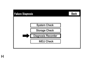
Select "Diagnosis Recorder" from the "Failure Diagnosis" screen.
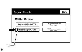
| *a | Green Indicator |
Push the "Recording ON/OFF" switch to enable "BT Communication Trace output" to be selected.
- HINT:
-
When the green "Recording ON/OFF" indicator is illuminated, the "BT Communication Trace output" is grayed out and cannot be selected.
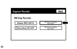
Select "BT Communication Trace output" for 3 seconds.
According to the instructions on the screen, save the "Bluetooth" Connection History data to a USB memory device.
Select "Recording ON/OFF" on the Diagnosis Recorder screen to illuminate the green "Recording ON/OFF" indicator.
- HINT:
-
Make sure that the green "Recording ON/OFF" indicator returns to illuminated state, after performing the above procedure.
Connect the USB memory device with the saved "Bluetooth" Connection History data to the GTS.
Turn the GTS on.
Enter the following menus: Advanced Function / Bluetooth Connection History.
According to the GTS screen, select the saved "Bluetooth" Connection History file.
When an item is stored for "Bluetooth" Connection History, record it before proceeding with troubleshooting.
| Item | Content |
|---|---|
| Occurrence Start Date/Time | Date and time of "Bluetooth" connection are displayed. |
| Occurrence End Date/Time | Date and time of "Bluetooth" disconnection are displayed. |
| History Type | Type of "Bluetooth" Connection History is displayed. |
| Result | "Bluetooth" connection result is displayed. |
| Contents | "Bluetooth" connection status is displayed. |
| "Bluetooth" Address | "Bluetooth" device address is displayed. |
| Continuance Time | The number of retries when "Bluetooth" connection was performed is displayed. |
| Result | Contents | Detail | Areas to be Checked |
|---|---|---|---|
| - | - | Ignition switch ACC | - |
| Result | Contents | Detail | Areas to be Checked |
|---|---|---|---|
| Success (HFP) | No Error | "Bluetooth" device was registered as a hands-free device properly. | - |
| Success (AVP) | No Error | "Bluetooth" device was registered as a "Bluetooth" audio device properly. | - |
| Success (HFP) ("Android Auto")
(w/ "Android Auto" Function) |
No Error | "Bluetooth" device was registered as a hands-free device properly. | - |
| Failure | Time Out | "Bluetooth" connection could not be established properly. | ·
Check that the "Bluetooth" device is in the cabin. ·
Check that the "Bluetooth" device is not connected to another device using the "Bluetooth" connection. ·
Restart the "Bluetooth" device and operate it again. |
| Authentication Error | Wrong PIN code was input for PIN code verification. | Perform "Bluetooth" device registration again. (Input PIN code correctly.) | |
| Confirmation button was not selected even though a passkey was displayed. | Perform "Bluetooth" device registration again. (When a passkey is displayed, select the confirmation button.) | ||
| A verification error occurred between the radio and display receiver assembly and "Bluetooth" device. | Restart the radio and display receiver assembly and "Bluetooth" device, and operate them again. | ||
| ACL Link Disconnection | "Bluetooth" connection was disconnected by operating the "Bluetooth" device. | Perform "Bluetooth" device registration again. | |
| "Bluetooth" connection could not be established due to wave interference around the vehicle. | Check for wave interference and perform "Bluetooth" device registration again. | ||
| "Bluetooth" device was outside the communication area. | Bring the "Bluetooth" device near the radio and display receiver assembly and perform "Bluetooth" device registration again. | ||
| "Bluetooth" setting on the "Bluetooth" device was off. | Change the "Bluetooth" setting to on and perform "Bluetooth" device registration again. | ||
| "Bluetooth" device was off. | Turn the "Bluetooth" device on and perform "Bluetooth" device registration again. | ||
| A malfunction of the "Bluetooth" device occurred. | Restart the "Bluetooth" device and operate it again. | ||
| Memory Write Failure | "Bluetooth" device information could not be stored in the radio and display receiver assembly. | Perform "Bluetooth" device registration again. | |
| Other Error | An error other than above occurred. | After turning the ignition switch off and back to ON again, perform "Bluetooth" device registration again. | |
| Failure ("Android Auto")
(w/ "Android Auto" Function) |
Time Out | "Bluetooth" connection could not be established properly. | ·
Check that the "Bluetooth" device is in the cabin. ·
Check that the "Bluetooth" device is not connected to another device using the "Bluetooth" connection. ·
Restart the "Bluetooth" device and operate it again. |
| Authentication Error | Wrong PIN code was input for PIN code verification. | Perform "Bluetooth" device registration again. (Input PIN code correctly.) | |
| Confirmation button was not selected even though a passkey was displayed. | Perform "Bluetooth" device registration again. (When a passkey is displayed, select the confirmation button.) | ||
| A verification error occurred between the radio and display receiver assembly and "Bluetooth" device. | Restart the radio and display receiver assembly and "Bluetooth" device, and operate them again. | ||
| ACL Link Disconnection | "Bluetooth" connection was disconnected by operating the "Bluetooth" device. | Perform "Bluetooth" device registration again. | |
| "Bluetooth" connection could not be established due to wave interference around the vehicle. | Check for wave interference and perform "Bluetooth" device registration again. | ||
| "Bluetooth" device was outside the communication area. | Bring the "Bluetooth" device near the radio and display receiver assembly and perform "Bluetooth" device registration again. | ||
| "Bluetooth" setting on the "Bluetooth" device was off. | Change the "Bluetooth" setting to on and perform "Bluetooth" device registration again. | ||
| "Bluetooth" device was off. | Turn the "Bluetooth" device on and perform "Bluetooth" device registration again. | ||
| A malfunction of the "Bluetooth" device occurred. | Restart the "Bluetooth" device and operate it again. | ||
| Memory Write Failure | "Bluetooth" device information could not be stored in the radio and display receiver assembly. | Perform "Bluetooth" device registration again. | |
| Other Error | An error other than above occurred. | After turning the ignition switch off and back to ON again, perform "Bluetooth" device registration again. | |
| Cancel | No Error | Registration was suspended by operating the radio and display receiver assembly or "Bluetooth" device. | - |
| Cancel ("Android Auto")
(w/ "Android Auto" Function) |
No Error | Registration was suspended by operating the radio and display receiver assembly or "Bluetooth" device. | - |
| Result | Contents | Detail | Areas to be Checked |
|---|---|---|---|
·
Auto Connect Success (HFP) ·
Manual Connect Success (HFP) |
No Error | "Bluetooth" device was connected as a hands-free device properly. | - |
·
Auto Connect Failure (HFP) ·
Manual Connect Failure (HFP) |
Time Out | "Bluetooth" connection could not be established properly. | ·
Check that the "Bluetooth" device is in the cabin. ·
Check that the "Bluetooth" device is not connected to another device using the "Bluetooth" connection. ·
Restart the "Bluetooth" device and operate it again. |
| Authentication Error | Verification of authentication key between the radio and display receiver assembly and "Bluetooth" device failed. | If "Bluetooth" connection fails multiple times, perform registration again. | |
| A verification error occurred between the radio and display receiver assembly and "Bluetooth" device. | Restart the radio and display receiver assembly and "Bluetooth" device, and operate them again. | ||
| Page Time Out | Could not find a "Bluetooth" device near the radio and display receiver assembly. | Bring the "Bluetooth" device near the radio and display receiver assembly and perform "Bluetooth" connection again. | |
| "Bluetooth" connection could not be established due to wave interference around the vehicle. | Check for wave interference and perform "Bluetooth" connection again. | ||
| "Bluetooth" device was outside the communication area. | Bring the "Bluetooth" device near the radio and display receiver assembly and perform "Bluetooth" connection again. | ||
| "Bluetooth" setting on the "Bluetooth" device was off. | Change the "Bluetooth" setting to on and perform "Bluetooth" connection again. | ||
| "Bluetooth" device was off. | Turn the "Bluetooth" device on and perform "Bluetooth" connection again. | ||
| A malfunction of the "Bluetooth" device occurred. | Restart the "Bluetooth" device and operate it again. |
| Result | Contents | Detail | Areas to be Checked |
|---|---|---|---|
·
Auto Connect Failure (HFP) ·
Manual Connect Failure (HFP) |
ACL Link Disconnection | "Bluetooth" connection was disconnected by operating the "Bluetooth" device. | Perform "Bluetooth" connection again. |
| "Bluetooth" connection could not be established due to wave interference around the vehicle. | Check for wave interference and perform "Bluetooth" connection again. | ||
| "Bluetooth" device was outside the communication area. | Bring the "Bluetooth" device near the radio and display receiver assembly and perform "Bluetooth" connection again. | ||
| "Bluetooth" setting on the "Bluetooth" device was off. | Change the "Bluetooth" setting to on and perform "Bluetooth" connection again. | ||
| "Bluetooth" device was off. | Turn the "Bluetooth" device on and perform "Bluetooth" connection again. | ||
| A malfunction of the "Bluetooth" device occurred. | Restart the "Bluetooth" device and operate it again. | ||
| SDP Error | HFP was disabled on the "Bluetooth" device. | Enable HFP on the "Bluetooth" device and perform "Bluetooth" connection again. | |
| "Bluetooth" device which operation had not been confirmed was used. | Check that the "Bluetooth" device is hands-free compatible and its operation has been confirmed.
Click here( 202006,999999,_56,_078379,_0380999,RM100000001P0XD,)
|
||
| Other Error | An error other than above occurred. | After turning the ignition switch off and back to ON again, perform "Bluetooth" device registration again. | |
| Manual Connect Cancel (HFP) | No Error | Connection was interrupted by operating the radio and display receiver assembly or "Bluetooth" device. | - |
| Result | Contents | Detail | Areas to be Checked |
|---|---|---|---|
·
Auto Connect Success (AVP) ·
Manual Connect Success (AVP) |
No Error | "Bluetooth" device was connected as a "Bluetooth" audio device properly. | - |
·
Auto Connect Failure (AVP) ·
Manual Connect Failure (AVP) |
Time Out | "Bluetooth" connection could not be established properly. | ·
Check that the "Bluetooth" device is in the cabin. ·
Check that the "Bluetooth" device is not connected to another device using the "Bluetooth" connection. ·
Restart the "Bluetooth" device and operate it again. |
| Authentication Error | Verification of authentication key between the radio and display receiver assembly and "Bluetooth" device failed. | If "Bluetooth" connection fails multiple times, perform registration again. | |
| A verification error occurred between the radio and display receiver assembly and "Bluetooth" device. | Restart the radio and display receiver assembly and "Bluetooth" device, and operate them again. | ||
| Page Time Out | Could not find a "Bluetooth" device near the radio and display receiver assembly. | Bring the "Bluetooth" device near the radio and display receiver assembly and perform "Bluetooth" connection again. | |
| "Bluetooth" connection could not be established due to wave interference around the vehicle. | Check for wave interference and perform "Bluetooth" connection again. | ||
| "Bluetooth" device was outside the communication area. | Bring the "Bluetooth" device near the radio and display receiver assembly and perform "Bluetooth" connection again. | ||
| "Bluetooth" setting on the "Bluetooth" device was off. | Change the "Bluetooth" setting to on and perform "Bluetooth" connection again. | ||
| "Bluetooth" device was off. | Turn the "Bluetooth" device on and perform "Bluetooth" connection again. | ||
| A malfunction of the "Bluetooth" device occurred. | Restart the "Bluetooth" device and operate it again. |
| Result | Contents | Detail | Areas to be Checked |
|---|---|---|---|
·
Auto Connect Failure (AVP) ·
Manual Connect Failure (AVP) |
ACL Link Disconnection | "Bluetooth" connection was disconnected by operating the "Bluetooth" device. | Perform "Bluetooth" connection again. |
| "Bluetooth" connection could not be established due to wave interference around the vehicle. | Check for wave interference and perform "Bluetooth" connection again. | ||
| "Bluetooth" device was outside the communication area. | Bring the "Bluetooth" device near the radio and display receiver assembly and perform "Bluetooth" connection again. | ||
| "Bluetooth" setting on the "Bluetooth" device was off. | Change the "Bluetooth" setting to on and perform "Bluetooth" connection again. | ||
| "Bluetooth" device was off. | Turn the "Bluetooth" device on and perform "Bluetooth" connection again. | ||
| A malfunction of the "Bluetooth" device occurred. | Restart the "Bluetooth" device and operate it again. | ||
| SDP Error | AVP was disabled on the "Bluetooth" device. | Enable AVP on the "Bluetooth" device and perform "Bluetooth" connection again. | |
| "Bluetooth" device which operation had not been confirmed was used. | Check that the "Bluetooth" device is "Bluetooth" audio compatible and its operation has been confirmed.
Click here( 202006,999999,_56,_078379,_0380999,RM100000001P0XD,)
|
||
| Other Error | An error other than above occurred. | After turning the ignition switch off and back to ON again, perform "Bluetooth" device registration again. | |
| Manual Connect Cancel (AVP) | No Error | Connection was interrupted by operating the radio and display receiver assembly or "Bluetooth" device. | - |
| Result | Contents | Detail | Areas to be Checked |
|---|---|---|---|
| Connect Success (HFP) ("Android Auto")
(w/ "Android Auto" Function) |
No Error | "Bluetooth" device was connected as a hands-free device properly. | - |
| Connect Failure (HFP) ("Android Auto")
(w/ "Android Auto" Function) |
Time Out | "Bluetooth" connection could not be established properly. | ·
Check that the "Bluetooth" device is in the cabin. ·
Check that the "Bluetooth" device is not connected to another device using the "Bluetooth" connection. ·
Restart the "Bluetooth" device and operate it again. |
| Authentication Error | Verification of authentication key between the radio and display receiver assembly and "Bluetooth" device failed. | If "Bluetooth" connection fails multiple times, perform registration again. | |
| A verification error occurred between the radio and display receiver assembly and "Bluetooth" device. | Restart the radio and display receiver assembly and "Bluetooth" device, and operate them again. | ||
| Page Time Out | Could not find a "Bluetooth" device near the radio and display receiver assembly. | Bring the "Bluetooth" device near the radio and display receiver assembly and perform "Bluetooth" connection again. | |
| "Bluetooth" connection could not be established due to wave interference around the vehicle. | Check for wave interference and perform "Bluetooth" connection again. | ||
| "Bluetooth" device was outside the communication area. | Bring the "Bluetooth" device near the radio and display receiver assembly and perform "Bluetooth" connection again. | ||
| "Bluetooth" setting on the "Bluetooth" device was off. | Change the "Bluetooth" setting to on and perform "Bluetooth" connection again. | ||
| "Bluetooth" device was off. | Turn the "Bluetooth" device on and perform "Bluetooth" connection again. | ||
| A malfunction of the "Bluetooth" device occurred. | Restart the "Bluetooth" device and operate it again. |
| Result | Contents | Detail | Areas to be Checked |
|---|---|---|---|
| Connect Failure (HFP) ("Android Auto")
(w/ "Android Auto" Function) |
ACL Link Disconnection | "Bluetooth" connection was disconnected by operating the "Bluetooth" device. | Perform "Bluetooth" connection again. |
| "Bluetooth" connection could not be established due to wave interference around the vehicle. | Check for wave interference and perform "Bluetooth" connection again. | ||
| "Bluetooth" device was outside the communication area. | Bring the "Bluetooth" device near the radio and display receiver assembly and perform "Bluetooth" connection again. | ||
| "Bluetooth" setting on the "Bluetooth" device was off. | Change the "Bluetooth" setting to on and perform "Bluetooth" connection again. | ||
| "Bluetooth" device was off. | Turn the "Bluetooth" device on and perform "Bluetooth" connection again. | ||
| A malfunction of the "Bluetooth" device occurred. | Restart the "Bluetooth" device and operate it again. | ||
| SDP Error | HFP was disabled on the "Bluetooth" device. | Enable HFP on the "Bluetooth" device and perform "Bluetooth" connection again. | |
| "Bluetooth" device which operation had not been confirmed was used. | Check that the "Bluetooth" device is hands-free compatible and its operation has been confirmed.
( 202006,999999,_56,_078379,_0380999,RM100000001P0XD,)
|
||
| Other Error | An error other than above occurred. | After turning the ignition switch off and back to ignition switch to ON again, perform "Bluetooth" device registration again. | |
| Connect Cancel (HFP) ("Android Auto")
(w/ "Android Auto" Function) |
No Error | Connection was interrupted by operating the radio and display receiver assembly or "Bluetooth" device. | - |
| Result | Contents | Detail | Areas to be Checked |
|---|---|---|---|
| Disconnection Complete (HFP) | Link Loss | The "Bluetooth" device was moved outside of the communication area. | Move the "Bluetooth" device into the communication area. |
| "Bluetooth" connection was disconnected due to wave interference around the vehicle. | Check for wave interference and perform "Bluetooth" connection again. | ||
| A malfunction of the "Bluetooth" device occurred. | Restart the "Bluetooth" device and operate it again. | ||
| Disconnection from Partner | "Bluetooth" connection was disconnected by operating the "Bluetooth" device. | - | |
| Disconnection from Self | "Bluetooth" connection was disconnected by operating the radio and display receiver assembly. | - | |
| Other Error | An error other than above occurred. | After turning the ignition switch off and back to ON again, perform "Bluetooth" device registration again. | |
| Disconnection Complete (HFP) ("Android Auto")
(w/ "Android Auto" Function) |
Link Loss | The "Bluetooth" device was moved outside of the communication area. | Move the "Bluetooth" device into the communication area. |
| "Bluetooth" connection was disconnected due to wave interference around the vehicle. | Check for wave interference and perform "Bluetooth" connection again. | ||
| A malfunction of the "Bluetooth" device occurred. | Restart the "Bluetooth" device and operate it again. | ||
| Disconnection from Partner | "Bluetooth" connection was disconnected by operating the "Bluetooth" device. | - | |
| Disconnection from Self | "Bluetooth" connection was disconnected by operating the radio and display receiver assembly. | - | |
| Other Error | An error other than above occurred. | After turning the ignition switch off and back to ON again, perform "Bluetooth" device registration again. | |
| Disconnection Complete (AVP) | Link Loss | The "Bluetooth" device was moved outside of the communication area. | Move the "Bluetooth" device into the communication area. |
| "Bluetooth" connection was disconnected due to wave interference around the vehicle. | Check for wave interference and perform "Bluetooth" connection again. | ||
| A malfunction of the "Bluetooth" device occurred. | Restart the "Bluetooth" device and operate it again. | ||
| Disconnection from Partner | "Bluetooth" connection was disconnected by operating the "Bluetooth" device. | - | |
| Disconnection from Self | "Bluetooth" connection was disconnected by operating the radio and display receiver assembly. | - | |
| Other Error | An error other than above occurred. | After turning the ignition switch off and back to ON again, perform "Bluetooth" device registration again. |
| Result | Contents | Detail | Areas to be Checked |
|---|---|---|---|
| Success | No Error | Call was made properly. | - |
| Failure | Out of Service | Outside the cellular phone service area. | Move the vehicle into a cellular phone service area, check that the "Bluetooth" device is connected to the vehicle and operate the device again. |
| Redial Regulation | Redial of the "Bluetooth" device was restricted and could not make a hands-free call. | Restart the "Bluetooth" device and operate it again. | |
| Other Error | Could not make a hands-free call due to a "Bluetooth" device malfunction. | Restart the "Bluetooth" device and operate it again. | |
| Could not make a hands-free call due to a radio and display receiver assembly malfunction. | After turning the ignition switch off and back to ON again, perform "Bluetooth" device registration again. | ||
| Could not make a hands-free call from the radio and display receiver assembly because the call status of the "Bluetooth" device was not transmitted to the radio and display receiver assembly. | Restart the "Bluetooth" device and operate it again. |
- HINT:
-
The names of items in the Result and Contents columns of the table may differ from the actual item displayed on the GTS.
Bluetooth Connection Sequence (Registration from onboard device)
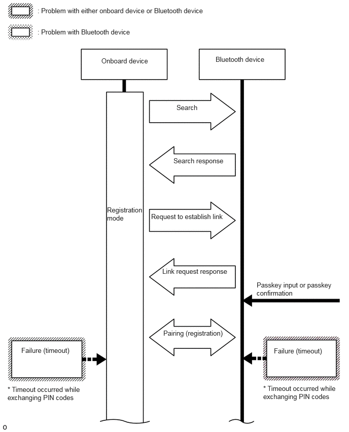
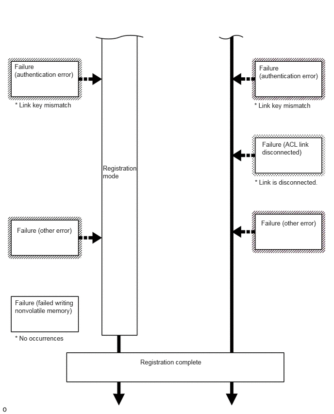
Bluetooth Connection Sequence (Connection from onboard device after registration)
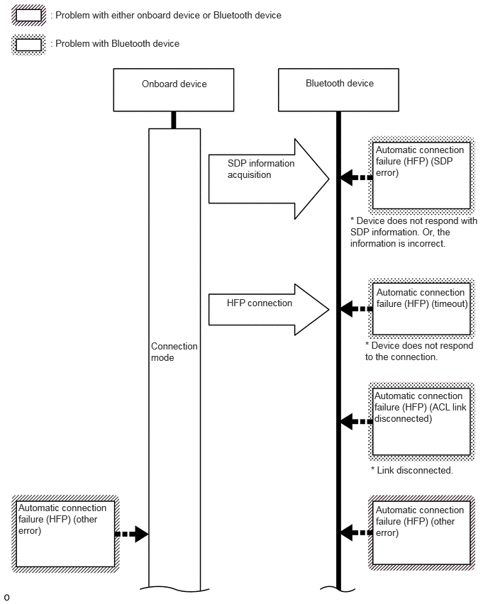
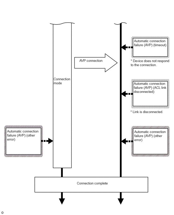
Bluetooth Connection Sequence (Registration from Bluetooth device)
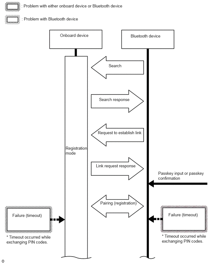
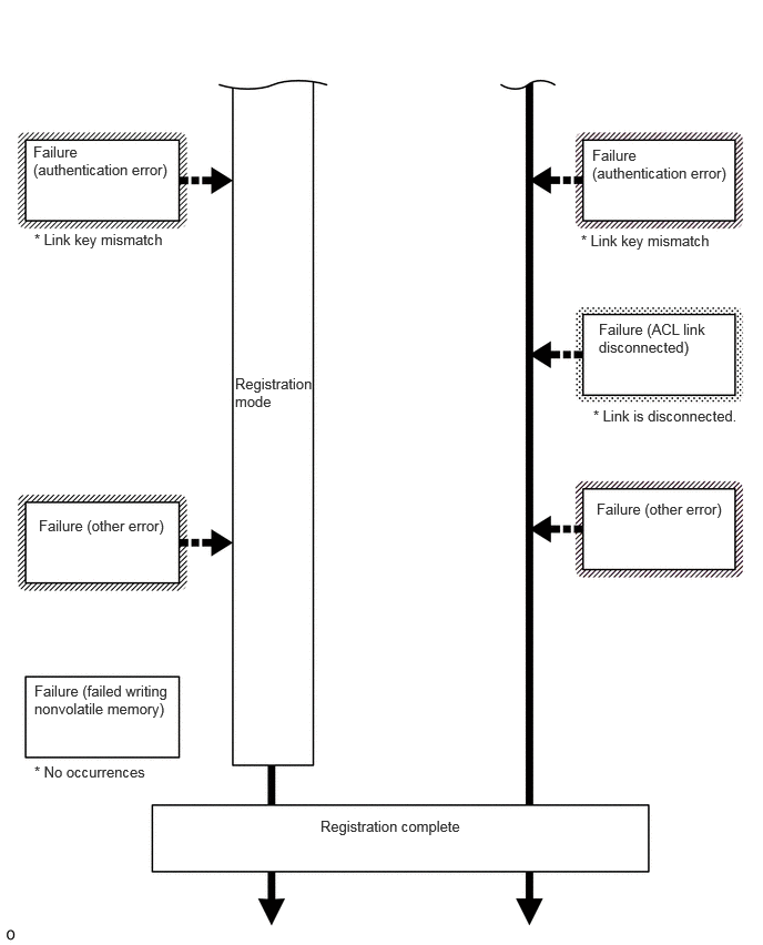
Bluetooth Connection Sequence (Connection from Bluetooth device after registration)
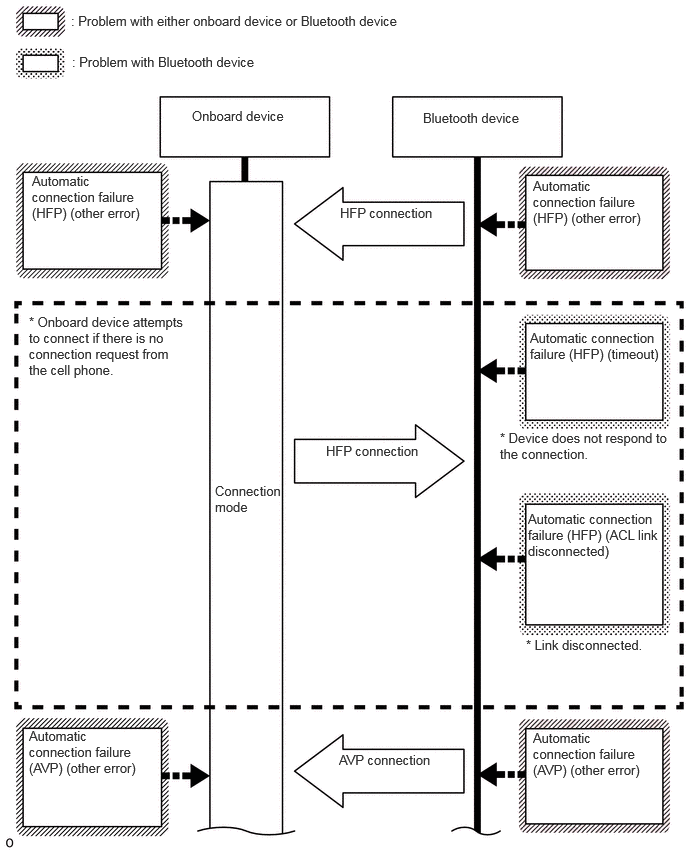
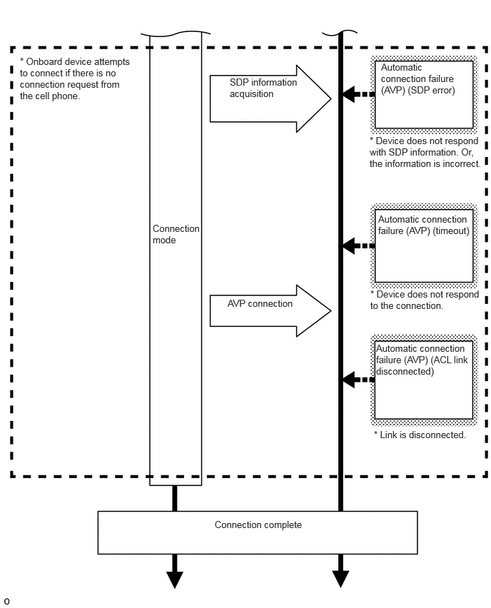
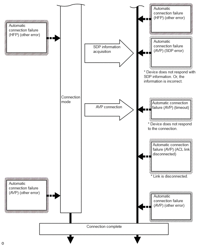
Bluetooth Connection Sequence (Automatic Connection)
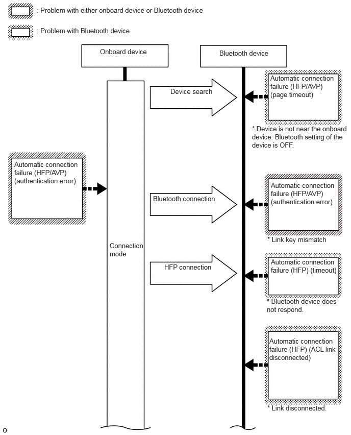
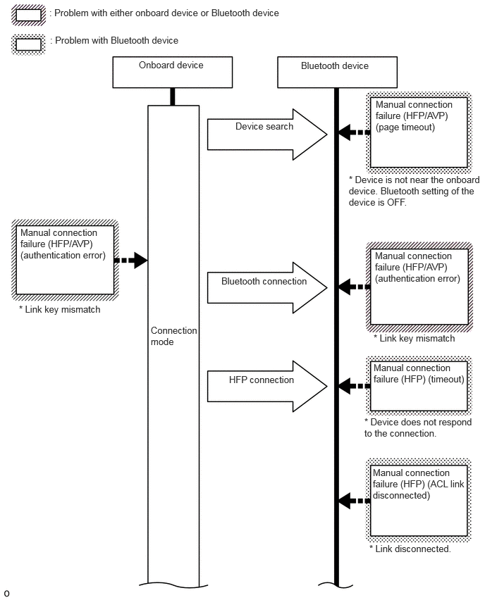
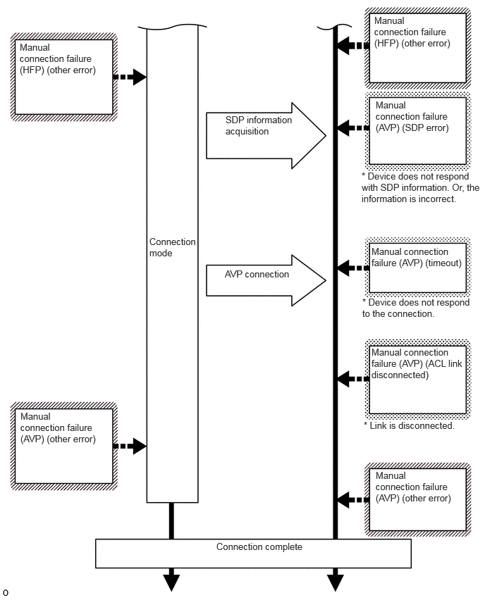
Bluetooth Connection Sequence (Manual Connection)
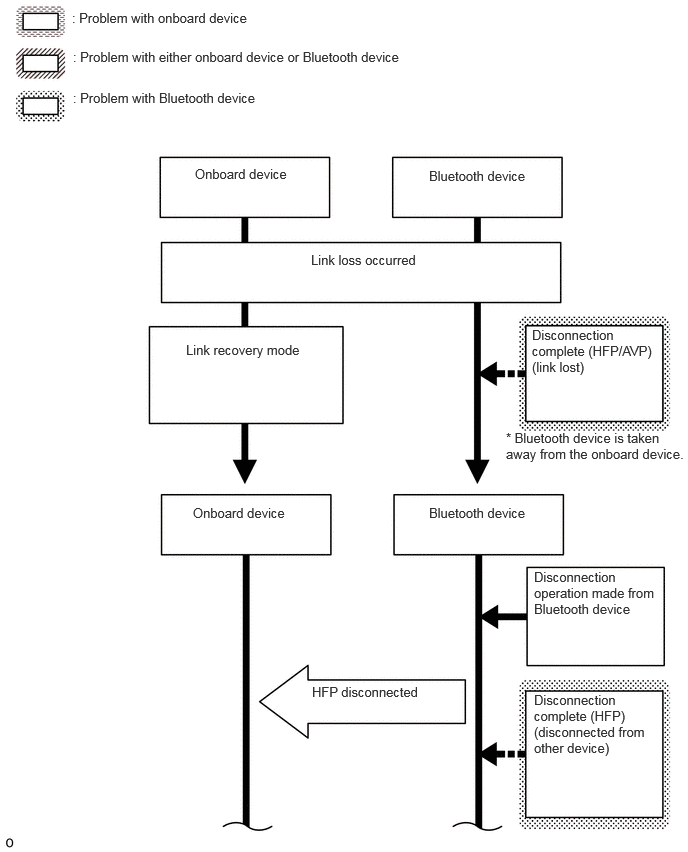
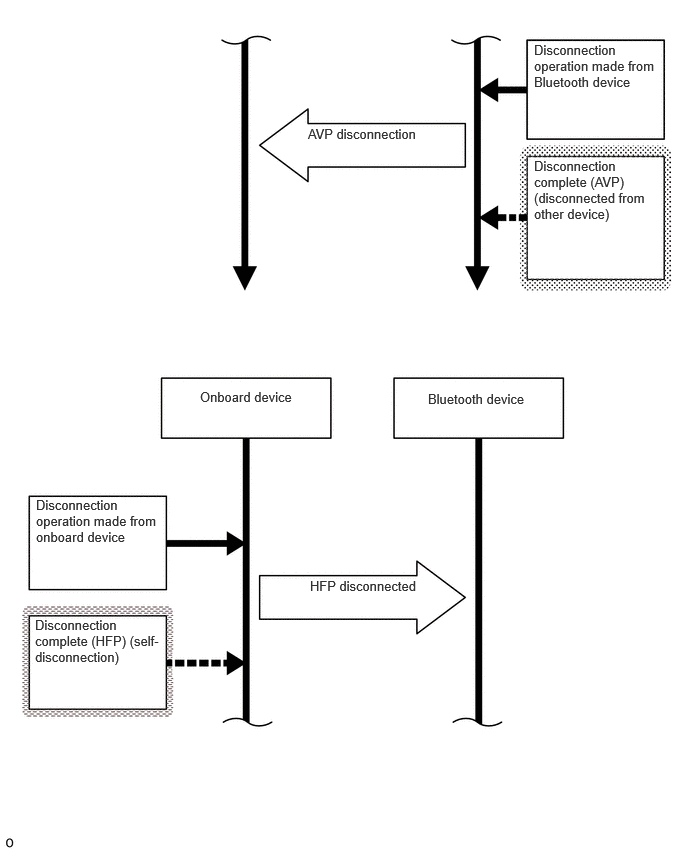
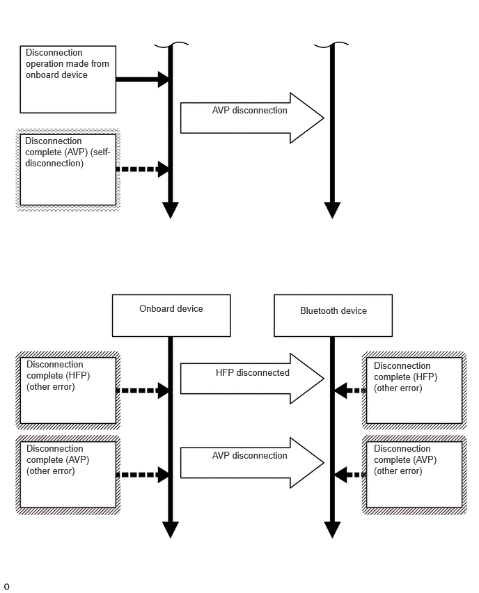
Bluetooth Connection Sequence (Disconnection Processing)
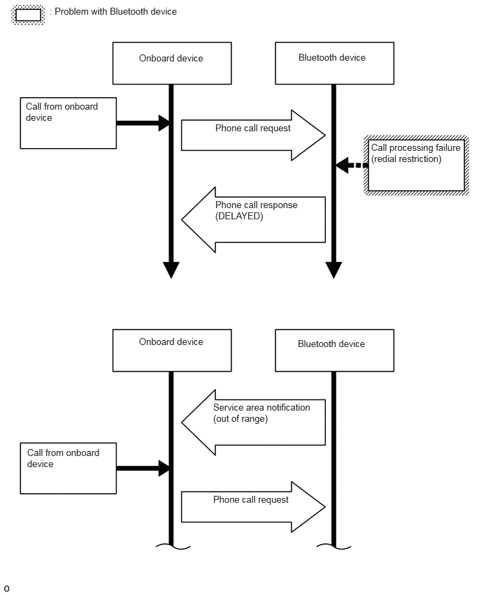
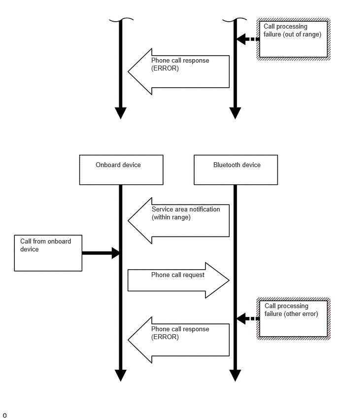
Bluetooth Connection Sequence (Phone Call Processing)
- HINT:
-
Bluetooth Related Terms:
Marking in Repair Manual Description HFP (Hands Free Profile) Profile for making and receiving telephone calls. AVP (Audio/Video Profile) Profile for music playback, lyric display and operation. ACL (Asynchronous Connection Less) One of the Bluetooth connection methods used for data transfer. SDP (Service Discovery Protocol) Protocol used to determine what kind of service is supported by the connected device.
CHECK "Wi-Fi" CONNECTION HISTORY
- HINT:
-
This function is used to check the connection history when the connection between the radio and display receiver assembly and a "Wi-Fi" device is unstable.
Check "Wi-Fi" Connection History.
- HINT:
- ·
"Wi-Fi" Connection History displays data stored in the internal memory of the ECU, such as the date a "Wi-Fi" connection was attempted and the state of a "Wi-Fi" connection.
·By checking "Wi-Fi" Connection History, the date, cause, etc. of a "Wi-Fi" device failing to register or connect can be analyzed.
·"Wi-Fi" Connection History indicates the estimated cause of a malfunction, but does not determine it. Therefore, checking "Wi-Fi" Connection History may not improve the problem.
·Performing an inspection using the GTS before recording the "Wi-Fi" Connection History may clear the history.
Connect the USB memory device to the No. 1 stereo jack adapter assembly.
Select "Failure Diagnosis" from the "Service Menu" screen.
Select "Diagnosis Recorder" from the "Failure Diagnosis" screen.
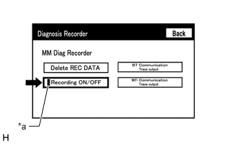
| *a | Green Indicator |
Push the "Recording ON/OFF" switch to enable "Wi-Fi" Communication Trace output" to be selected.
- HINT:
-
When the green "Recording ON/OFF" indicator is illuminated, the "Wi-Fi" Communication Trace output" is grayed out and cannot be selected.
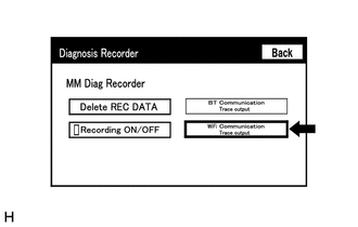
Select "Wi-Fi Communication Trace output" for 3 seconds.
According to the instructions on the screen, save the "Wi-Fi" Connection History data to a USB memory device.
Select "Recording ON/OFF" on the Diagnosis Recorder screen to illuminate the green "Recording ON/OFF" indicator.
- HINT:
-
Make sure that the green "Recording ON/OFF" indicator returns to illuminated state, after performing the above procedure.
Connect the USB memory device with the saved "Wi-Fi" Connection History data to the GTS.
Turn the GTS on.
Enter the following menus: Advanced Function / Wi-Fi Connection History.
According to the GTS screen, select the saved "Wi-Fi" Connection History file.
When a value for an item is displayed in "Wi-Fi" Connection History, record it before proceeding with troubleshooting.
| Item | Content |
|---|---|
| Occurrence Date/Time | Year is displayed in 4 digits and month, date, hour, minute and second are displayed in 2 digits |
| Result | Connect/Disconnect Success |
| Timeout | |
| Communication Error | |
| Authentication Failure | |
| Disconnection Failure | |
| Other Failure | |
| Contents | No Error |
| AP Connection Error | |
| AP Connection Error (WPS) | |
| DHCP Connection Error | |
| DNS Connection Error | |
| HTTP Connection Error | |
| Other Error | |
| Destination MAC Address | Displayed in lower case hexadecimal format with "-" inserted every two characters. |
| Destination SSID Data is displayed as ASCII code | Data is displayed as ASCII code |
| WLAN Standard | 802.11 b |
| 802.11 g | |
| 802.11 n | |
| Undetectable | |
| Received Signal Strength | -127 dBm to +127 dBm |
| Data Rate | 1.0 Mbps |
| 2.0 Mbps | |
| 5.5 Mbps | |
| 6.0 Mbps | |
| 6.5 Mbps | |
| 9.0 Mbps | |
| 11.0 Mbps | |
| 12.0 Mbps | |
| 13.0 Mbps | |
| 18.0 Mbps | |
| 19.5 Mbps | |
| 24.0 Mbps | |
| 26.0 Mbps | |
| 36.0 Mbps | |
| 39.0 Mbps | |
| 48.0 Mbps | |
| 52.0 Mbps | |
| 54.0 Mbps | |
| 58.5 Mbps | |
| 65.0 Mbps | |
| Undetectable | |
| Packet Error Rate | Displayed in decimal format with "%" |
- HINT:
-
If there is nothing to display in the "Content" column, "-" or "No Information" is displayed.
APPLICATION LINK RESET PROCEDURE (w/ Application Link Function)
Duplicate the problem symptom.
Check for DTCs and repair the systems for which any DTCs are output.
Check cellular phone compatibility.
Check if the cellular phone/vehicle is compatible.
If the cellular phone is not compatible, recommend to the customer a compatible cellular phone.
Delete the radio and display receiver assembly information from the cellular phone.
The procedure varies based on phone model. Contact the service provider or cellular phone manufacturer if assistance is required.
- NOTICE:
-
Only perform this step if the customer is present and approves.
Remove the Application Link app from the phone.
- NOTICE:
-
Only perform this step if the customer is present and approves.
The procedure varies based on phone model. Contact the service provider or cellular phone manufacturer if assistance is required.
Reset the phone.
- NOTICE:
-
Only perform this step if the customer is present and approves.
Reboot the cellular phone. For instructions on how to reset a cellular device, refer to the appropriate manufacturer's website.
Reinstall the Application Link app on the phone. (If removed.)
The procedure varies based on phone model. Contact the service provider or cellular phone manufacturer if assistance is required.
Delete all personal data from the radio and display receiver assembly.
Delete all personal data from the radio and display receiver assembly.
- NOTICE:
-
Only perform this step if the customer is present and approves.
- HINT:
-
Re-installation of applications must be completed before applications will appear on the radio and display receiver assembly.
Disconnect the cable from the negative (-) battery terminal.
Delete all personal data from the radio and display receiver assembly.
- NOTICE:
-
After turning the ignition switch off, waiting time may be required before disconnecting the cable from the negative (-) battery terminal.
Record all radio station presets.
Disconnect the cable from the negative (-) battery terminal and leave it disconnected for 2 minutes.
Check if the problem symptom disappears