NAVIGATION / MULTI INFO DISPLAY NAVIGATION ECU REMOVAL
CAUTION / NOTICE / HINT
- NOTICE:
- ·
When replacing the radio and display receiver assembly or navigation ECU, always replace it with a new one. If a radio and display receiver assembly or navigation ECU which was installed to another vehicle is used, the following may occur:
-A communication malfunction DTC may be stored.
-The radio and display receiver assembly or navigation ECU may not operate normally.
·When performing the following work, the navigation system may restart when turning the ignition switch ACC (due to radio and display receiver assembly and navigation ECU certification).
-Repair or replace the negative (-) battery terminal due to it being disconnected or depleted.
-The radio and display receiver assembly or navigation ECU replacement or removal and installation.
- HINT:
- ·
Use the same procedure for RHD and LHD vehicles.
·The procedure listed below is for RHD vehicles.
PROCEDURE

 33622
1.DISCONNECT NO. 1 SHIFT LEVER KNOB COVER (for Automatic Transmission)
33622
1.DISCONNECT NO. 1 SHIFT LEVER KNOB COVER (for Automatic Transmission)
33504F
2.REMOVE SHIFT LEVER KNOB SUB-ASSEMBLY
for Manual Transmission:
for Automatic Transmission:
58840Q
3.REMOVE SHIFTING HOLE COVER ASSEMBLY (for Manual Transmission)
35970F
4.REMOVE POSITION INDICATOR HOUSING ASSEMBLY (for Automatic Transmission)
55405B
5.REMOVE CENTER INSTRUMENT CLUSTER FINISH PANEL SUB-ASSEMBLY (for Manual Air Conditioning System)
55900
6.REMOVE AIR CONDITIONING CONTROL ASSEMBLY (for Automatic Air Conditioning System)
55410C
7.REMOVE INSTRUMENT CLUSTER FINISH PANEL ASSEMBLY
8.REMOVE DISPLAY AND NAVIGATION ASSEMBLY WITH BRACKET
for Type A:
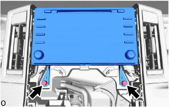
Remove the 2 bolts.

Remove the 2 bolts.
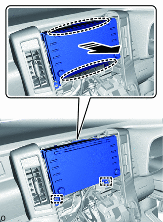

|
Place Hands Here |

|
Remove in this Direction |
Place both hands at the position shown in the illustration, pull in the direction indicated by the arrow to detach the guide and remove the display and navigation assembly with bracket.
Disconnect each connector.
- HINT:
-
When disconnecting each connector, do not remove the navigation wire.
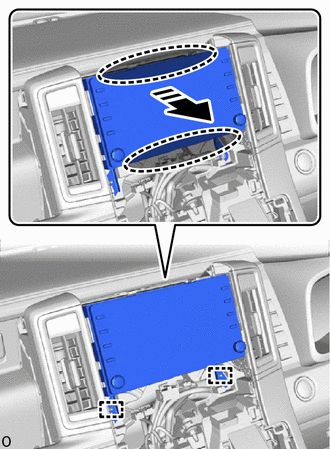
for Type B:
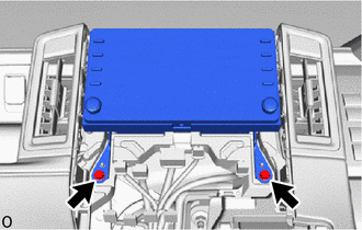
Remove the 2 bolts.
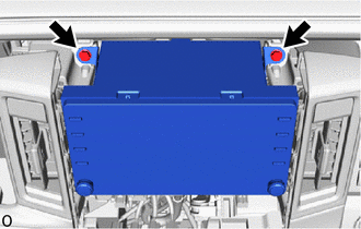
Remove the 2 bolts.
|
|
Place Hands Here |
|
|
Remove in this Direction |
Place both hands at the position shown in the illustration, pull in the direction indicated by the arrow to detach the guide and remove the display and navigation assembly with bracket.
Disconnect each connector.
- HINT:
-
When disconnecting each connector, do not remove the navigation wire.
86842
9.REMOVE NO. 1 NAVIGATION WIRE
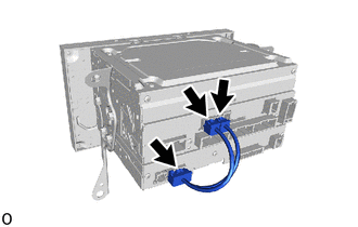
Disconnect the 3 connectors and remove the No. 1 navigation wire.
86211
10.REMOVE NO. 1 RADIO BRACKET
for Type A:
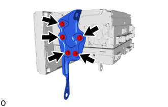
Remove the 5 screws and No. 1 radio bracket.
for Type B:
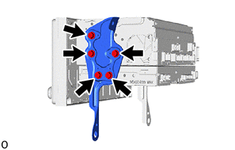
Remove the 5 screws and No. 1 radio bracket.
86212
11.REMOVE NO. 2 RADIO BRACKET
for Type A:
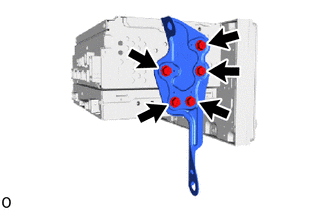
Remove the 5 screws and No. 2 radio bracket.
for Type B:
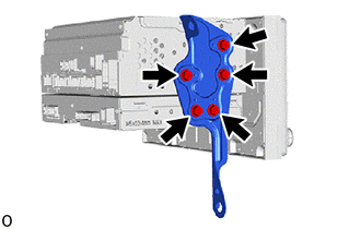
Remove the 5 screws and No. 2 radio bracket.
86841
12.REMOVE NAVIGATION ECU