BRAKE CONTROL / DYNAMIC CONTROL SYSTEMS ELECTRONICALLY CONTROLLED BRAKE SYSTEM(w/ VSC OFF Switch) DATA LIST / ACTIVE TEST
DATA LIST
- NOTICE:
-
In the table below, the values listed under "Normal Condition" are reference values. Do not depend solely on these reference values when deciding whether a part is faulty or not.
- HINT:
-
Using the GTS to read the Data List allows the values or states of switches, sensors, actuators and other items to be read without removing any parts. This non-intrusive inspection can be very useful because intermittent conditions or signals may be discovered before parts or wiring is disturbed. Reading the Data List information early in troubleshooting is one way to save diagnostic time.
Warm up the engine.
Turn the ignition switch off.
Connect the GTS to the DLC3.
Turn the ignition switch to ON.
Turn the GTS on.
Enter the following menus: Chassis / Brake / Data List.
According to the display on the GTS, read the Data List.
- Chassis > Brake > Data List
-
Tester Display Measurement Item Range Normal Condition Diagnostic Note Total Distance Traveled - Unit Total Distance Traveled unit km / mile - - Total Distance Traveled Total distance traveled Min.: 0
Max.: 16777215- - IG1 Voltage Value IG1 terminal voltage value (value detected by ECU) Min.: 0.0 V
Max.: 25.5 V·Ignition switch ON: 10.5 to 16.0 V*1
·Ignition switch ON: 11.0 to 14.0 V*2
Changes in proportion to battery voltage BS1 Voltage Value +BS terminal voltage value (value detected by ECU) Min.: 0.0 V
Max.: 25.5 VIgnition switch ON: 11.0 to 14.0 V Changes in proportion to battery voltage
- HINT:
-
This is the voltage detected at terminal +BS (which supplies power to each solenoid) of the skid control ECU (brake actuator assembly)
Motor Power Supply Voltage +BM terminal voltage value (value detected by ECU) Min.: 0.0 V
Max.: 25.5 VIgnition switch ON: 11.0 to 14.0 V Changes in proportion to battery voltage
- HINT:
-
This is the voltage detected at terminal +BM (which supplies power to the ABS motor) of the skid control ECU (brake actuator assembly)
FR Wheel Speed Front wheel speed sensor RH reading Min.: 0.0 km/h (0 mph)
Max.: 6553.5 km/h (4072 mph)Vehicle stopped: 0.0 km/h (0.0 mph) When driving at constant speed: No large fluctuations FL Wheel Speed Front wheel speed sensor LH reading Min.: 0.0 km/h (0 mph)
Max.: 6553.5 km/h (4072 mph)Vehicle stopped: 0.0 km/h (0.0 mph) When driving at constant speed: No large fluctuations RR Wheel Speed Rear wheel speed sensor RH reading Min.: 0.0 km/h (0 mph)
Max.: 6553.5 km/h (4072 mph)Vehicle stopped: 0.0 km/h (0.0 mph) When driving at constant speed: No large fluctuations RL Wheel Speed Rear wheel speed sensor LH reading Min.: 0.0 km/h (0 mph)
Max.: 6553.5 km/h (4072 mph)Vehicle stopped: 0.0 km/h (0.0 mph) When driving at constant speed: No large fluctuations FR Wheel Acceleration Front wheel RH acceleration Min.: -200.840 m/s2
Max.: 199.271 m/s2Vehicle stopped: 0.000 m/s2
During deceleration: -200.840 to 0.000 m/s2
During acceleration: 0.000 to 199.271 m/s2During deceleration/acceleration: Changes continuously FL Wheel Acceleration Front wheel LH acceleration Min.: -200.840 m/s2
Max.: 199.271 m/s2Vehicle stopped: 0.000 m/s2
During deceleration: -200.840 to 0.000 m/s2
During acceleration: 0.000 to 199.271 m/s2During deceleration/acceleration: Changes continuously RR Wheel Acceleration Rear wheel RH acceleration Min.: -200.840 m/s2
Max.: 199.271 m/s2Vehicle stopped: 0.000 m/s2
During deceleration: -200.840 to 0.000 m/s2
During acceleration: 0.000 to 199.271 m/s2During deceleration/acceleration: Changes continuously RL Wheel Acceleration Rear wheel LH acceleration Min.: -200.840 m/s2
Max.: 199.271 m/s2Vehicle stopped: 0.000 m/s2
During deceleration: -200.840 to 0.000 m/s2
During acceleration: 0.000 to 199.271 m/s2During deceleration/acceleration: Changes continuously Master Cylinder Sensor 1 Master cylinder pressure sensor pressure (value detected by ECU) Min.: -1.00 MPa
Max.: 23.99 MPaBrake pedal released: -1.00 to 0.00 MPa Reading increases when brake pedal is depressed Zero Point of M/C Memorized zero point value of master cylinder pressure sensor Min.: -12.5 MPa
Max.: 12.4 MPa- - M/C Sensor Grade Master cylinder pressure sensor change (value detected by ECU) Min.: -30 MPa/s
Max.: 225 MPa/sBrake pedal released or pedal held at constant position: 0 MPa/s When brake pedal is being operated: Changes in proportion with the pedal movement speed Lateral G Lateral G Min.: -25.105 m/s2
Max.: 24.908 m/s2Turning right: -25.105 to 0.000 m/s2
Turning left: 0.000 to 24.908 m/s2During turning: Changes in proportion with lateral acceleration Forward and Rearward G Forward and rearward G Min.: -25.105 m/s2
Max.: 24.908 m/s2During deceleration: -25.105 to 0.000 m/s2
During acceleration: 0.000 to 24.908 m/s2During acceleration/deceleration: Changes in proportion with acceleration Zero Point of Decele2 Memorized zero point value of lateral G Min.: -25.105 m/s2
Max.: 24.908 m/s2- - Zero Point of Decele Memorized zero point value of forward and rearward G Min.: -25.105 m/s2
Max.: 24.908 m/s2- - Yaw Rate Sensor Value Yaw rate sensor Min.: -128°/s
Max.: 127°/sVehicle stopped: 0°/s
Turning right: -128 to 0°/s
Turning left: 0 to 127°/s- Zero Point of Yaw Rate Sensor Memorized zero point value of yaw rate sensor Min.: -128°/s
Max.: 127°/s- - Steering Angle Value Steering angle sensor Min.: -3276.8°
Max.: 3276.7°Turning left: 0.0 to 3276.7°
Turning right: -3276.8 to 0.0°- Zero Point of Steering Angle Memorized zero point value of steering angle sensor Min.: -3276.8°
Max.: 3276.7°- - MT Voltage Value ABS motor drive voltage value Min.: 0.0 V
Max.: 25.5 VIgnition switch ON: 11.0 to 14.0 V Changes in proportion to battery voltage
- HINT:
-
This is the voltage output (which supplies power to the ABS motor) from the skid control ECU (brake actuator assembly) to the ABS motor relay
Solenoid Power Supply Voltage Solenoid power supply voltage value Min.: 0.0 V
Max.: 25.5 VIgnition switch ON: 11.0 to 14.0 V Changes in proportion to battery voltage
- HINT:
-
This is the voltage output (which supplies power to each solenoid) from the skid control ECU (brake actuator assembly) to the ABS solenoid relay
Vehicle Speed Vehicle speed Min.: 0.0 km/h (0 mph)
Max.: 6553.5 km/h (4072 mph)Vehicle stopped: 0.0 km/h (0.0 mph) When driving at constant speed: No large fluctuations Engine Revolutions Engine speed Min.: 0.0 km/h (0 mph)
Max.: 6553.5 km/h (4072 mph)Engine stopped: 0 rpm When engine speed is constant: No large fluctuations Accelerator Opening Angle % Percentage of accelerator pedal opening angle Min.: 0.0%
Max.: 127.5%Accelerator pedal released: 0.0% During accelerator pedal operation: Changes in proportion with the pedal movement Real Engine Torque Real engine torque Min.: -1024.000 Nm
Max.: 1023.000 Nm- - Gear Position Gear position information fail / 1st / 2nd / 3rd / 4th / 5th / 6th / 7th / 8th / 9th / 10th / P/N / R Actual gear position for Automatic Transmission Shift Lever Position Shift lever position information fail / 1st / 2nd / 3rd / 4th / 5th / 6th / B / D/M / N / P / R / No input Actual shift lever position for Automatic Transmission TRC(TRAC)/VSC OFF Mode TRC/VSC off mode Normal mode (TRC(TRAC) ON/VSC ON) /
TRC(TRAC) OFF mode (TRC(TRAC) OFF/VSC ON) /
Not defined /
VSC OFF mode (TRC(TRAC) OFF/VSC OFF)Normal mode (TRC(TRAC) ON/VSC ON): Normal mode
TRC(TRAC) OFF mode (TRC(TRAC) OFF/VSC ON): AUTO LSD mode
Not defined: Not defined
VSC OFF mode (TRC(TRAC) OFF/VSC OFF): VSC off mode- FR Target Oil Pressure The value of the target oil pressure applied to the front brake RH Min.: 0.0 MPa
Max.: 20.0 MPa- Operating the brake pedal: Varies depending on the target oil pressure FL Target Oil Pressure The value of the target oil pressure applied to the front brake LH Min.: 0.0 MPa
Max.: 20.0 MPa- Operating the brake pedal: Varies depending on the target oil pressure RR Target Oil Pressure The value of the target oil pressure applied to the rear brake RH Min.: 0.0 MPa
Max.: 20.0 MPa- Operating the brake pedal: Varies depending on the target oil pressure RL Target Oil Pressure The value of the target oil pressure applied to the rear brake LH Min.: 0.0 MPa
Max.: 20.0 MPa- Operating the brake pedal: Varies depending on the target oil pressure Vehicle Speed Vehicle speed (vehicle speed used for each control) Min.: 0.0 km/h (0 mph)
Max.: 6553.5 km/h (4072 mph)Vehicle stopped: 0.0 km/h (0.0 mph) When driving at constant speed: No large fluctuations Vehicle Speed Grade Vehicle acceleration Min.: -25.105 m/s2
Max.: 24.908 m/s2Vehicle stopped: 0.000 m/s2
During deceleration: -25.105 to 0.000 m/s2
During acceleration: 0.000 to 24.908 m/s2During deceleration/acceleration: Changes continuously Vehicle Stop Time from IG ON Time vehicle stopped after ignition switch turned to ON Min.: 0 s
Max.: 1275 s- - Travel Distance from IG ON Driving time after ignition switch turned to ON Min.: 0 s
Max.: 1275 s- - IG Switch Ignition switch ON status OFF / ON - - Stop Light SW Stop light switch assembly (STP terminal input) OFF / ON OFF: Brake pedal released
ON: Brake pedal depressed- HINT:
-
The brake pedal state is determined using the voltage at terminal STP
Parking Brake SW Parking brake switch assembly OFF / ON OFF: Parking brake released
ON: Parking brake applied- Brake Pedal Load Sensing SW Brake pedal load sensing switch (brake pedal support assembly) OFF / ON OFF: Brake pedal load sensing switch (brake pedal support assembly) OFF
ON: Brake pedal load sensing switch (brake pedal support assembly) ONw/ Brake Pedal Load Sensing Switch Reverse Position Switch Back-up light switch assembly OFF / ON OFF: Shift lever in any position other than R
ON: Shift lever in R- Stop Light Relay ·STOP LP relay (stop light relay) (STP2 terminal input)*3
·Stop light relay (stop light switch assembly) (STP2 terminal input)*4
OFF / ON OFF: STOP LP relay (stop light relay) off*3
OFF: Stop light relay (stop light switch assembly) off*4
ON: STOP LP relay (stop light relay) on*3
ON: Stop light relay (stop light switch assembly) on*4- HINT:
-
The stop light state is determined using the voltage at terminal STP2
·w/ STOP LP Relay (Stop Light Relay)
·w/ Rear Combination Light (for LED Type) (w/ Pre-collision System)
Inspection Mode Inspection mode OFF / ON OFF: Normal mode
ON: Inspection mode- HINT:
-
Refer to utility for details on how to enter inspection mode*5
TRC(TRAC) Control TRC control status Out of controlling / Under Controlling Out of controlling: During not control
Under Controlling: During control- TRC(TRAC) Engine Control TRC engine control status Out of controlling / Under Controlling Out of controlling: During not control
Under Controlling: During control- TRC(TRAC) Brake Control TRC brake control status Out of controlling / Under Controlling Out of controlling: During not control
Under Controlling: During control- FR Wheel VSC Ctrl Status Front wheel RH VSC control status Out of controlling / Under Controlling Out of controlling: During not control
Under Controlling: During control- FL Wheel VSC Ctrl Status Front wheel LH VSC control status Out of controlling / Under Controlling Out of controlling: During not control
Under Controlling: During control- RR Wheel VSC Ctrl Status Rear wheel RH VSC control status Out of controlling / Under Controlling Out of controlling: During not control
Under Controlling: During control- RL Wheel VSC Ctrl Status Rear wheel LH VSC control status Out of controlling / Under Controlling Out of controlling: During not control
Under Controlling: During control- FR Wheel ABS Ctrl Status Front wheel RH ABS control status Out of controlling / Under Controlling Out of controlling: During not control
Under Controlling: During control- FL Wheel ABS Ctrl Status Front wheel LH ABS control status Out of controlling / Under Controlling Out of controlling: During not control
Under Controlling: During control- RR Wheel ABS Ctrl Status Rear wheel RH ABS control status Out of controlling / Under Controlling Out of controlling: During not control
Under Controlling: During control- RL Wheel ABS Ctrl Status Rear wheel LH ABS control status Out of controlling / Under Controlling Out of controlling: During not control
Under Controlling: During control- HAB Control HAB control status OFF / ON OFF: During not control
ON: During control- Fail Status Fail status OFF / ON OFF: During not fail status
ON: During fail statusw/ Brake Pedal Load Sensing Switch Fail Control Fail control OFF / ON OFF: During not control
ON: During controlw/ Brake Pedal Load Sensing Switch BA Ctrl Status BA control status OFF / ON OFF: During not control
ON: During control- PBA Ctrl Status PBA control status OFF / ON OFF: During not control
ON: During controlw/ Pre-collision System Stop Light Relay State for ECU Control ·STOP LP relay (stop light relay) status (STPO terminal output) (for ECU control)*3
·Stop light relay (stop light switch assembly) status (STPO terminal output) (for ECU control)*4
OFF / ON OFF: STOP LP relay (stop light relay) off (stop light off)*3
OFF: Stop light relay (stop light switch assembly) off (stop light off)*4
ON: STOP LP relay (stop light relay) on (stop light on)*3
ON: Stop light relay (stop light switch assembly) on (stop light on)*4·w/ STOP LP Relay (Stop Light Relay)
·w/ Rear Combination Light (for LED Type) (w/ Pre-collision System)
Engine Stop by Stop and Start System Engine stopped by stop and start system status OFF / ON OFF: Engine not stopped by stop and start control
ON: Engine stopped by stop and start controlw/ Stop and Start System Solenoid State for ECU Control ABS solenoid relay status (for ECU control) OFF / ON OFF: ABS solenoid relay not operating
ON: ABS solenoid relay operating- Motor State for ECU Control ABS motor relay status (for ECU control) OFF / ON OFF: ABS motor relay not operating
ON: ABS motor relay operating- Operation History of IG OFF while Vehicle is moving History of ignition switch turned off when vehicle is in motion OFF / ON OFF: No history
ON: History of ignition switch turned off with vehicle speed 3 km/h (2 mph) or higher- Dealer Mode Dealer Mode (Signal Check mode or Calibration mode) status OFF / ON OFF: Normal mode
ON: Dealer Mode (Signal Check mode or Calibration mode)- HINT:
- ·
for details on Dealer Mode (Signal Check), refer to test mode procedure*4
·for details on Dealer Mode (Calibration), refer to utility*5
Zero Point Memory State of Steering Angle Sensor Steering angle sensor zero point memorization status Zero point is not memorized / Zero point is memorized - - HINT:
-
The steering angle sensor zero point is acquired when the vehicle is being driven in a straight line at a speed of 15 km/h (9 mph) or more for approximately 1 second
ABS Solenoid (SRLR) Rear pressure reduction solenoid LH status OFF / ON OFF: Not Operating
ON: Operating (pressure reduction)- HINT:
-
The solenoid valve controls the brake fluid pressure of the wheel cylinder of the vehicle
ABS Solenoid (SRLH) Rear pressure holding solenoid LH status OFF / ON OFF: Not Operating
ON: Operating (pressure holding)- HINT:
-
The solenoid valve controls the brake fluid pressure of the wheel cylinder of the vehicle
ABS Solenoid (SRRR) Rear pressure reduction solenoid RH status OFF / ON OFF: Not Operating
ON: Operating (pressure reduction)- HINT:
-
The solenoid valve controls the brake fluid pressure of the wheel cylinder of the vehicle
ABS Solenoid (SRRH) Rear pressure holding solenoid RH status OFF / ON OFF: Not Operating
ON: Operating (pressure holding)- HINT:
-
The solenoid valve controls the brake fluid pressure of the wheel cylinder of the vehicle
ABS Solenoid (SFLR) Front pressure reduction solenoid LH status OFF / ON OFF: Not Operating
ON: Operating (pressure reduction)- HINT:
-
The solenoid valve controls the brake fluid pressure of the wheel cylinder of the vehicle
ABS Solenoid (SFLH) Front pressure holding solenoid LH status OFF / ON OFF: Not Operating
ON: Operating (pressure holding)- HINT:
-
The solenoid valve controls the brake fluid pressure of the wheel cylinder of the vehicle
ABS Solenoid (SFRR) Front pressure reduction solenoid RH status OFF / ON OFF: Not Operating
ON: Operating (pressure reduction)- HINT:
-
The solenoid valve controls the brake fluid pressure of the wheel cylinder of the vehicle
ABS Solenoid (SFRH) Front pressure holding solenoid RH status OFF / ON OFF: Not Operating
ON: Operating (pressure holding)- HINT:
-
The solenoid valve controls the brake fluid pressure of the wheel cylinder of the vehicle
TRC(TRAC)/VSC Solenoid (SM2) Master cylinder cut solenoid (Brake Pressure Control Solenoid "B") status OFF / ON OFF: Not Operating
ON: Operating (pressure regulation)- HINT:
-
Depending on the operating conditions, the master cylinder cut solenoid valves regulate the brake fluid pressure generated by the pump motor
TRC(TRAC)/VSC Solenoid (SM1) Master cylinder cut solenoid (Brake Pressure Control Solenoid "A") status OFF / ON OFF: Not Operating
ON: Operating (pressure regulation)- HINT:
-
Depending on the operating conditions, the master cylinder cut solenoid valves regulate the brake fluid pressure generated by the pump motor
TRC(TRAC)/VSC Solenoid (SRC2) Reservoir cut solenoid (Brake Pressure Control Solenoid "D") status OFF / ON OFF: Not Operating
ON: Operating (brake fluid supplied to pump motor)- HINT:
-
When the brakes are operating, the reservoir cut solenoid valves supply brake fluid from the brake master cylinder reservoir assembly to the pump motor as necessary
TRC(TRAC)/VSC Solenoid (SRC1) Reservoir cut solenoid (Brake Pressure Control Solenoid "C") status OFF / ON OFF: Not Operating
ON: Operating (brake fluid supplied to pump motor)- HINT:
-
When the brakes are operating, the reservoir cut solenoid valves supply brake fluid from the brake master cylinder reservoir assembly to the pump motor as necessary
ABS Motor Relay ABS motor relay OFF / ON OFF: ABS motor not operating
ON: ABS motor operating- STPO ·STOP LP relay (stop light relay) status (STPO terminal output)*3
·Stop light relay (stop light switch assembly) status (STPO terminal output)*4
OFF / ON OFF: STOP LP relay (stop light relay) off (stop light off)*3
OFF: Stop light relay (stop light switch assembly) off (stop light off)*4
ON: STOP LP relay (stop light relay) on (stop light on)*3
ON: Stop light relay (stop light switch assembly) on (stop light on)*4·w/ STOP LP Relay (Stop Light Relay)
- HINT:
-
When STPO is ON, the STOP LP relay (stop light relay) turns ON and the stop lights illuminate
·w/ Rear Combination Light (for LED Type) (w/ Pre-collision System)
- HINT:
-
When STPO is ON, the Stop light relay (stop light switch assembly) turns ON and the stop lights illuminate
*1: w/ Stop and Start System
*2: w/o Stop and Start System
*3: w/ STOP LP Relay (Stop Light Relay)
*4: w/ Rear Combination Light (for LED Type) (w/ Pre-collision System)
*5: for entering inspection mode: Click hereBrake>BRAKE CONTROL / DYNAMIC CONTROL SYSTEMS>ELECTRONICALLY CONTROLLED BRAKE SYSTEM (w/ VSC OFF Switch)>UTILITY201902,999999,_54,_078667,_0385049,RM100000001GK1P,
*6: for performing Dealer Mode (Signal Check): Click hereBrake>BRAKE CONTROL / DYNAMIC CONTROL SYSTEMS>ELECTRONICALLY CONTROLLED BRAKE SYSTEM (w/ VSC OFF Switch)>TEST MODE PROCEDURE201906,999999,_54,_078667,_0385049,RM100000001IQ9G,
*7: for entering Dealer Mode (Calibration): Click hereBrake>BRAKE CONTROL / DYNAMIC CONTROL SYSTEMS>ELECTRONICALLY CONTROLLED BRAKE SYSTEM (w/ VSC OFF Switch)>UTILITY201902,999999,_54,_078667,_0385049,RM100000001GK1P,
CHECK FOR INTERMITTENT PROBLEMS
- HINT:
-
A momentary interruption (open circuit) in the connectors and/or wire harness between the sensors and ECUs can be detected using the Data List function of the GTS.
Turn the ignition switch off.
Connect the GTS to the DLC3.
Turn the ignition switch to ON.
Turn the GTS on.
Enter the following menus: Chassis / Brake / Data List.
Check the data related to power supply fluctuations.
- HINT:
-
A momentary interruption (open circuit) cannot be detected for 3 seconds after the ignition switch is turned to ON (initial check).
- Chassis > Brake > Data List
-
Tester Display Measurement Item Range Normal Condition Diagnostic Note EFI Communication Open EFI communication open detection Normal / Under intermittent Normal: Normal
Under intermittent: Momentary interruptionRelated DTC: U010087 Yaw Rate Open Yaw rate sensor (airbag ECU assembly) open detection Normal / Under intermittent Normal: Normal
Under intermittent: Momentary interruptionRelated DTC: U012587 Deceleration Open Acceleration sensor (airbag ECU assembly) open detection Normal / Under intermittent Normal: Normal
Under intermittent: Momentary interruptionRelated DTC: U012587 Steering Open Steering angle sensor open detection Normal / Under intermittent Normal: Normal
Under intermittent: Momentary interruptionRelated DTC: U012687
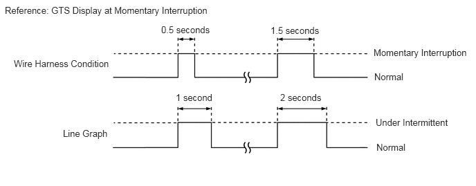
Push the line graph button to display the line graph.
Check for intermittent shorts, etc.
- OK:
Normal is displayed.
- HINT:
-
If "Under intermittent" remains displayed on the GTS, measure the resistance between the skid control ECU (brake actuator assembly) and each sensor or ECM.
While observing the screen, gently jiggle the connector or wire harness between the ECU and each sensors, or between ECUs.
- OK:
Normal is displayed.
- HINT:
- ·
If a momentary interruption occurs and Under intermittent is displayed on the GTS, Under intermittent will remain displayed on the GTS for 1 second after the circuit returns to normal.
 0.073,0.073 3.729,0.323 3.656,0.25 10 false Reference: GTS Display at Momentary Interruption 0.208,0.875 1.823,1.292 1.615,0.417 10 false Wire Harness Condition 0.948,1.927 1.792,2.26 0.844,0.333 10 false Line Graph 2.646,1.385 3.365,1.594 0.719,0.208 10 false 1 second 4.219,1.385 4.948,1.563 0.729,0.177 10 false 2 seconds 4.073,0.375 4.896,0.594 0.823,0.219 10 false 1.5 seconds 2.427,0.365 3.25,0.531 0.823,0.167 10 false 0.5 seconds 5.656,1.76 6.927,2.073 1.271,0.313 10 false Under Intermittent 5.667,2.135 6.417,2.469 0.75,0.333 10 false Normal 5.625,0.708 7.104,1 1.479,0.292 10 false Momentary Interruption 5.635,1.073 6.385,1.396 0.75,0.323 10 false Normal
·If the display changes, this indicates that there has been a momentary interruption (open circuit) in the connector and/or wire harness. In this case, repair or replace the connectors and/or wire harnesses as one of them is faulty.
ACTIVE TEST
- HINT:
-
Using the GTS to perform Active Tests allows relays, VSVs, actuators and other items to be operated without removing any parts. This non-intrusive functional inspection can be very useful because intermittent operation may be discovered before parts or wiring is disturbed.
-
Performing Active Tests early in troubleshooting is one way to save diagnostic time. Data List information can be displayed while performing Active Tests.
Warm up the engine.
Turn the ignition switch off.
Connect the GTS to the DLC3.
Turn the ignition switch to ON.
Turn the GTS on.
Enter the following menus: Chassis / Brake / Active Test.
Perform the Active Test to check for incorrect operation or to narrow down malfunctioning areas.
- NOTICE:
- ·
Although the Active Test automatically turns off the pump motor after approximately 5 seconds in order to protect the motor, do not operate the pump motor repeatedly without sufficient waiting time in between.
·Although the Active Test automatically turns off each solenoid after approximately 2 seconds in order to protect the solenoid, do not operate the solenoids repeatedly without sufficient waiting time in between.
·Do not depress the brake pedal when only the pressure release solenoids valves are ON.
·Do not operate more than one solenoid at the same time, except for when operating the pressure hold solenoid and pressure release solenoid of the same wheel.
- Chassis > Brake > Active Test
-
Tester Display Measurement Item Control Range Restrict Condition Diagnostic Note EBS Relay Emergency brake signal operation Relay OFF / ON Vehicle condition: Vehicle stopped
- HINT:
-
To protect this actuator and solenoid, this test will only last 5 seconds.
Whether the hazard warning lights blink when the EBS Relay is ON can be confirmed ABS Solenoid Pressure holding solenoid (SFRH, SFLH, SRRH, SRLH)
Pressure reduction solenoid (SFRR, SFLR, SRRR, SRLR)Solenoid Start (Activate)
Solenoid SFRH / SFLH / SRRH / SRLH / SFRR / SFLR / SRRR / SRLRVehicle condition:
·Vehicle stopped
·Shift lever is in P (for automatic transmission)
·Shift lever is in neutral (for manual transmission)
·Apply the parking brake
- HINT:
-
To protect actuator and Solenoid(s), this test will continue for 25 seconds.
Refer to on-vehicle inspection for the brake actuator*1 VSC Solenoid Master cylinder cut solenoid (SMF (SM1), SMR (SM2))
Reservoir cut solenoid (SRCF (SRC1), SRCR (SRC2))Solenoid Start (Activate)
Solenoid SMF / SMR / SRCF / SRCRVehicle condition:
·Vehicle stopped
·Shift lever is in P (for automatic transmission)
·Shift lever is in neutral (for manual transmission)
·Apply the parking brake
- HINT:
-
To protect actuator and Solenoid(s), this test will continue for 25 seconds.
Check that the GTS display for the solenoid (SM1, SM2, SRC1 or SRC2) changes to ON/OFF during Solenoid Start (Activate) Motor Relay ABS motor relay Relay OFF / ON Vehicle condition: Vehicle stopped
- HINT:
-
To protect this actuator and solenoid, this test will only last 5 seconds.
Refer to on-vehicle inspection for the brake actuator* Stop Lamp Relay ·STOP LP relay (stop light relay)*2
·Stop light relay (stop light switch assembly)*3
Relay OFF / ON Vehicle condition: Vehicle stopped
- HINT:
-
To protect this actuator and solenoid, this test will only last 5 seconds.
·w/ STOP LP Relay (Stop Light Relay):
With the brake pedal released, check that the stop lights illuminate and the value of STOP LP relay (stop light relay) on the GTS changes to ON when Stop Lamp Relay is ON
·w/ Rear Combination Light (for LED Type) (w/ Pre-collision System):
With the brake pedal released, check that the stop lights illuminate and the value of stop light relay (stop light switch assembly) on the GTS changes to ON when Stop Lamp Relay is ON
*2: w/ STOP LP Relay (Stop Light Relay)
*3: w/ Rear Combination Light (for LED Type) (w/ Pre-collision System)