METER / GAUGE / DISPLAY METER / GAUGE SYSTEM Speed Signal Circuit
DESCRIPTION
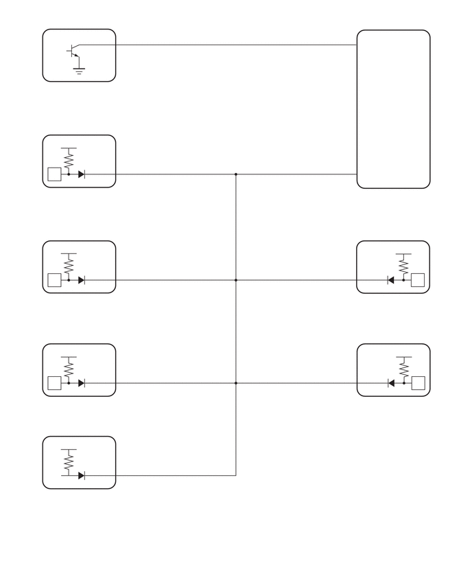
The combination meter assembly receives the vehicle speed signal from this circuit. The wheel speed sensors produce an output that varies according to the vehicle speed. The wheel speed sensor output is received by the brake actuator assembly (skid control ECU) which uses this information to create the vehicle speed signal*a. The vehicle speed signal consists of pulses sent to the combination meter assembly from the brake actuator assembly (skid control ECU). To create this signal, 12 V is output from IG2 which is behind a resistor in the combination meter assembly. This voltage is sent to the brake actuator assembly (skid control ECU). The pulse signal is created by switching the transistor in the brake actuator assembly (skid control ECU) on and off, making the voltage on the wire drop to 0 V. A similar system is used for the output of this signal from the combination meter assembly via terminal +S. A voltage of 12 V or 5 V is applied to terminal +S from each ECU or relay that is connected to this terminal. The transistor in the combination meter assembly is controlled by the signal from the brake actuator assembly (skid control ECU). When this transistor is turned on, this transistor makes the voltage supplied by the various ECUs (via their respective internal resistors) drop to 0 V. Each ECU connected to terminal +S of the combination meter assembly controls its respective system based on this pulse signal.
*a: This vehicle speed signal is created by the brake actuator assembly (skid control ECU). There is no actual component that is referred to as the vehicle speed sensor. In addition, for some systems, vehicle speed information may be received via CAN communication.
- HINT:
-
This circuit is used for the systems connected to terminal +S. This signal is not used for combination meter assembly operation. Combination meter assembly components such as the speedometer operate using data received via CAN communication.
WIRING DIAGRAM
CAUTION / NOTICE / HINT
- NOTICE:
- ·
Before replacing the ECM refer to the Service Bulletin.
·When replacing the combination meter assembly, always replace it with a new one. If a combination meter assembly which was installed to another vehicle is used, the information stored in it will not match the information from the vehicle and a DTC may be stored.
PROCEDURE
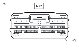
| *a | Front view of wire harness connector
(to Combination Meter Assembly) |
Disconnect the combination meter assembly connector.
Measure the voltage according to the value(s) in the table below.
- Standard Voltage:
Tester Connection Switch Condition Specified Condition N22-36 (+S) - Body ground Ignition switch ON 11 to 14 V
- HINT:
-
If any of the ECUs specified in the wiring diagram supplies power to the combination meter assembly, the combination meter assembly will output a waveform.
- Result:
Proceed to OK NG
OK
NG
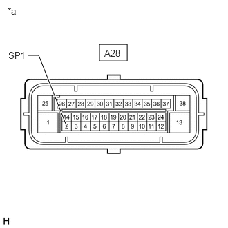
| *a | Front view of wire harness connector
(to Brake Actuator Assembly [Skid Control ECU]) |
Disconnect the brake actuator assembly (skid control ECU) connector.
Measure the voltage according to the value(s) in the table below.
- Standard Voltage:
Tester Connection Switch Condition Specified Condition A28-2 (SP1) - Body ground Ignition switch ON 11 to 14 V
- Result:
Proceed to OK NG
OK
NG
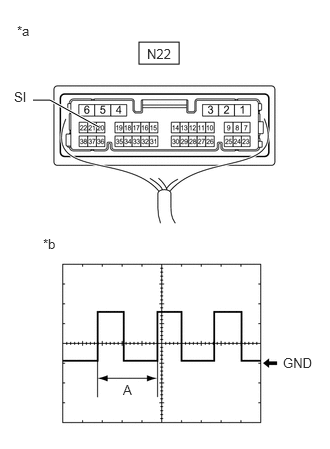
| *a | Component with harness connected
(Combination Meter Assembly) |
| *b | Waveform |
Check the input waveform.
Remove the combination meter assembly with the connector(s) still connected.
Connect an oscilloscope to terminal N22-20 (SI) and body ground.
Turn the ignition switch to ON.
Turn a wheel slowly.
Check the signal waveform according to the condition(s) in the table below.
| Item | Condition |
|---|---|
| Tester connection | N22-20 (SI) - Body ground |
| Tool setting | 5 V/DIV., 20 ms./DIV. |
| Condition | Ignition switch ON, wheel being rotated |
- OK:
The waveform is similar to that shown in the illustration.
- HINT:
-
When the system is functioning normally, one wheel revolution generates 4 pulses. As the vehicle speed increases, the width indicated by (A) in the illustration narrows.
- Result:
Proceed to OK NG
OK
NG
Disconnect the N22 combination meter assembly connector.
Disconnect the A28 brake actuator assembly (skid control ECU) connector.
Measure the resistance according to the value(s) in the table below.
- Standard Resistance:
Tester Connection Condition Specified Condition N22-20 (SI) - A28-2 (SP1) Always Below 1 Ω N22-20 (SI) or A28-2 (SP1) - Body ground Always 10 kΩ or higher
- Result:
Proceed to OK NG
OK
NG
*1: for 7GR-FKS
*2: for 1GD-FTV
*3: for Radio Receiver Type
*4: w/ Navigation System
*5: for Radio and Display Type
*6: w/ Entry and Start System
*7: for 12 Speakers
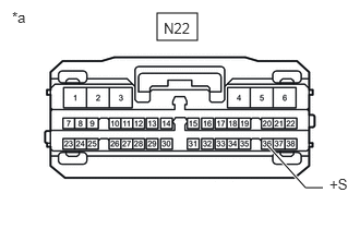
| *a | Front view of wire harness connector
(to Combination Meter Assembly) |
Disconnect the combination meter assembly connector.
Disconnect the N1*1 or N2*2 ECM connector.
Disconnect the O12 radio receiver assembly connector.*3
Disconnect the O9 navigation ECU connector.*4
Disconnect the O5 radio and display receiver assembly connector.*5
Disconnect the N169 stereo component amplifier assembly connector.*7
Disconnect the N156 certification ECU (smart key ECU assembly) connector.*6
Measure the resistance according to the value(s) in the table below.
- Standard Resistance:
Tester Connection Condition Specified Condition N22-36 (+S) - Body ground Always 10 kΩ or higher
- Result:
Proceed to OK NG
OK
NG
Check vehicle condition.
- Result:
Result Proceed to for Radio and Display Type A except Radio and Display Type B
A
B
| *a | Front view of wire harness connector
(to Combination Meter Assembly) |
Disconnect the combination meter assembly connector.
Disconnect the O5 radio and display receiver assembly connector.
Measure the voltage according to the value(s) in the table below.
- Standard Voltage:
Tester Connection Switch Condition Specified Condition N22-36 (+S) - Body ground Ignition switch ON 11 to 14 V
- HINT:
-
If the result is as specified, there may be a short circuit in the radio and display receiver assembly.
- Result:
Proceed to OK NG
OK
NG
Check vehicle condition.
- Result:
Result Proceed to w/ Navigation System A w/o Navigation System B
A
B
| *a | Front view of wire harness connector
(to Combination Meter Assembly) |
Disconnect the combination meter assembly connector.
Disconnect the O9 navigation ECU connector.
Measure the voltage according to the value(s) in the table below.
- Standard Voltage:
Tester Connection Switch Condition Specified Condition N22-36 (+S) - Body ground Ignition switch ON 11 to 14 V
- HINT:
-
If the result is as specified, there may be a short circuit in the navigation ECU.
- Result:
Proceed to OK NG
OK
NG
Check vehicle condition.
- Result:
Result Proceed to for 12 Speakers A except 12 Speakers B
A
B
| *a | Front view of wire harness connector
(to Combination Meter Assembly) |
Disconnect the combination meter assembly connector.
Disconnect the N169 stereo component amplifier assembly connector.
Measure the voltage according to the value(s) in the table below.
- Standard Voltage:
Tester Connection Switch Condition Specified Condition N22-36 (+S) - Body ground Ignition switch ON 11 to 14 V
- HINT:
-
If the result is as specified, there may be a short circuit in the stereo component amplifier assembly.
- Result:
Proceed to OK NG
OK
NG
Check vehicle condition.
- Result:
Result Proceed to w/ Entry and Start System A w/o Entry and Start System B
A
B
| *a | Front view of wire harness connector
(to Combination Meter Assembly) |
Disconnect the combination meter assembly connector.
Disconnect the N156 certification ECU (smart key ECU assembly) connector.
Measure the voltage according to the value(s) in the table below.
- Standard Voltage:
Tester Connection Switch Condition Specified Condition N22-36 (+S) - Body ground Ignition switch ON 11 to 14 V
- HINT:
-
If the result is as specified, there may be a short circuit in the certification ECU (smart key ECU assembly).
- Result:
Proceed to OK NG
OK
NG
Check vehicle condition.
- Result:
Result Proceed to for Radio Receiver Type A except Radio Receiver Type B
A
B
for 7GR-FKS:
for 1GD-FTV:
| *a | Front view of wire harness connector
(to Combination Meter Assembly) |
Disconnect the combination meter assembly connector.
Disconnect the O12 radio receiver assembly connector.
Measure the voltage according to the value(s) in the table below.
- Standard Voltage:
Tester Connection Switch Condition Specified Condition N22-36 (+S) - Body ground Ignition switch ON 11 to 14 V
- HINT:
-
If the result is as specified, there may be a short circuit in the radio receiver assembly.
- Result:
Proceed to OK NG
OK
NG
for 7GR-FKS:
for 1GD-FTV: