METER / GAUGE / DISPLAY METER / GAUGE SYSTEM(for Optitron Meter Type) Steering Pad Switch Circuit
DESCRIPTION
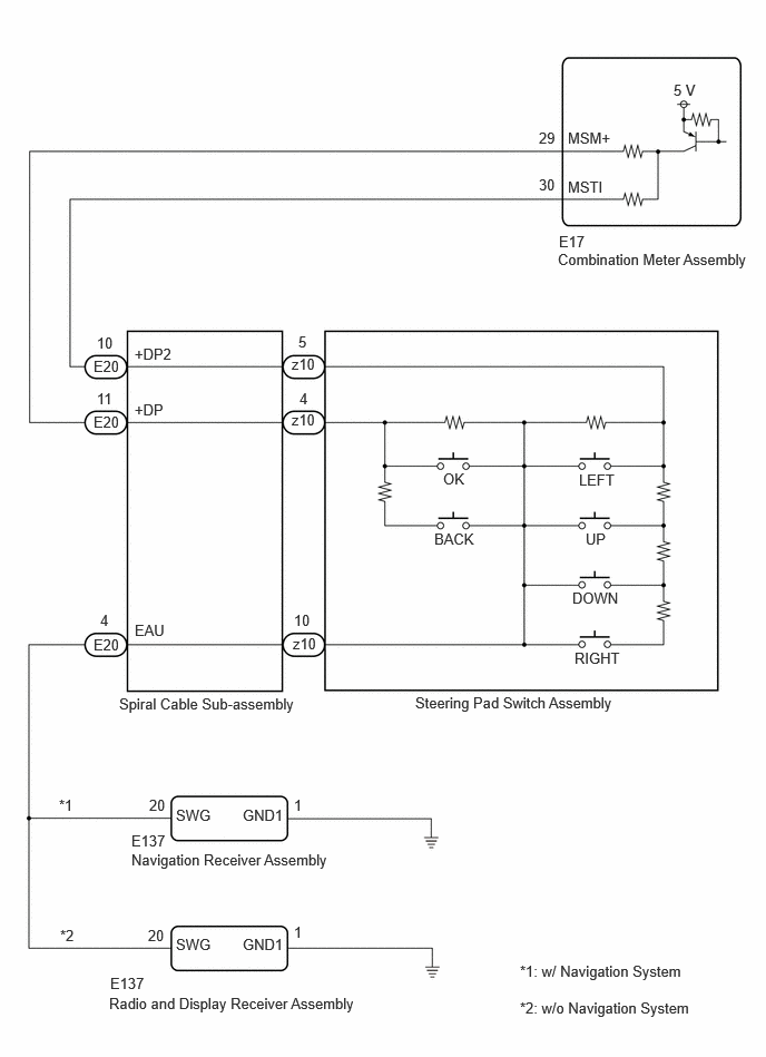
The combination meter assembly and steering pad switch assembly are connected via direct line. The multi-information display in the combination meter assembly is operated using the switches of the steering pad switch assembly.
WIRING DIAGRAM
CAUTION / NOTICE / HINT
- NOTICE:
-
When replacing the combination meter assembly, always replace it with a new one. If a combination meter assembly which was installed to another vehicle is used, the information stored in it will not match the information from the vehicle and a DTC may be stored.
PROCEDURE
Perform the Active Test according to the display on the GTS.
- Body Electrical > Combination Meter > Active Test
-
Tester Display Measurement Item Control Range Diagnostic Note Multi Switch (Up) Performs the same operation as pressing the up switch on steering pad switch OFF or ON - Multi Switch (Down) Performs the same operation as pressing the down switch on steering pad switch OFF or ON - Multi Switch (Left) Performs the same operation as pressing the left switch on steering pad switch OFF or ON - Multi Switch (Right) Performs the same operation as pressing the right switch on steering pad switch OFF or ON - Multi Switch (Enter) Performs the same operation as pressing the OK switch on steering pad switch OFF or ON - Multi Switch (Back) Performs the same operation as pressing the back switch on steering pad switch OFF or ON -
- Body Electrical > Combination Meter > Active Test
-
Tester Display Multi Switch (Up) - 50004 409 316
- Body Electrical > Combination Meter > Active Test
-
Tester Display Multi Switch (Down) - 50004 409 317
- Body Electrical > Combination Meter > Active Test
-
Tester Display Multi Switch (Left) - 50004 409 318
- Body Electrical > Combination Meter > Active Test
-
Tester Display Multi Switch (Right) - 50004 409 319
- Body Electrical > Combination Meter > Active Test
-
Tester Display Multi Switch (Enter) - 50004 409 320
- Body Electrical > Combination Meter > Active Test
-
Tester Display Multi Switch (Back) - 50004 409 321
- Result:
Result Proceed to Active Test can be performed correctly A Active Test cannot be performed correctly B
A
B
Read the Data List according to the display on the GTS.
- Body Electrical > Combination Meter > Data List
-
Tester Display Measurement Item Range Normal Condition Diagnostic Note Multi Switch (Up) Up switch on steering pad switch operation OFF or ON OFF: Switch released
ON: Switch pushed- Multi Switch (Down) Down switch on steering pad switch operation OFF or ON OFF: Switch released
ON: Switch pushed- Multi Switch (Left) Left switch on steering pad switch operation OFF or ON OFF: Switch released
ON: Switch pushed- Multi Switch (Right) Right switch on steering pad switch operation OFF or ON OFF: Switch released
ON: Switch pushed- Multi Switch (Enter) OK switch on steering pad switch operation OFF or ON OFF: Switch released
ON: Switch pushed- Multi Switch (Back) Back switch on steering pad switch operation OFF or ON OFF: Switch released
ON: Switch pushed-
- Body Electrical > Combination Meter > Data List
-
Tester Display Multi Switch (Up) Multi Switch (Down) Multi Switch (Left) Multi Switch (Right) Multi Switch (Enter) Multi Switch (Back) - 50003 409 12,13,14,15,16,17
- Result:
Result Proceed to The value of the Data List item is correct, and the combination meter assembly operates correctly A The value of the Data List item is correct, but the combination meter assembly does not operate correctly B The Data List item changes correctly C
A
B
C
- Result:
Proceed to OK NG
OK
NG
- Result:
Proceed to OK NG
OK
NG
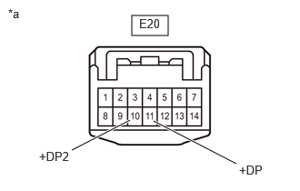
| *a | Front view of wire harness connector
(to Spiral Cable Sub-assembly) |
Measure the voltage according to the value(s) in the table below.
- Standard Voltage:
Tester Connection Condition Specified Condition Click Location & Routing(E20)Location & Routingewd_type=routing;type=c;code=E20
Click Connector(E20)Instrument Panel>Instrument Panel Wire / Telephone Computer Wire>Spiral Cable Sub-Assemblyewd_type=component;type=c;code=E20;pinno=10,11
E20-10 (+DP2) - Body ground Ignition switch ON 4.8 to 5.2 V E20-11 (+DP) - Body ground Ignition switch ON 4.8 to 5.2 V
- Result:
Proceed to OK NG
OK
NG
Choose the model to be inspected.
- Result:
Result Proceed to w/ Navigation System A w/o Navigation System B
A
B
Disconnect the E137 navigation receiver assembly connector.
Measure the resistance according to the value(s) in the table below.
- Standard Resistance:
Tester Connection Condition Specified Condition Click Location & Routing(E137,E20)Location & Routingewd_type=routing;type=c,c;code=E137,E20
Click Connector(E137)Instrument Panel>Instrument Panel Wire / Telephone Computer Wire>Navigation Receiver Assemblyewd_type=component;type=c;code=E137;pinno=20,1
Click Connector(E20)Instrument Panel>Instrument Panel Wire / Telephone Computer Wire>Spiral Cable Sub-Assemblyewd_type=component;type=c;code=E20;pinno=4
E137-20 (SWG) - E20-4 (EAU) Always Below 1 Ω E137-1 (GND1) - Body ground Always Below 1 Ω
- Result:
Proceed to OK NG
OK
NG
Disconnect the E137 radio and display receiver assembly connectors.
Measure the resistance according to the value(s) in the table below.
- Standard Resistance:
Tester Connection Condition Specified Condition Click Location & Routing(E137,E20)Location & Routingewd_type=routing;type=c,c;code=E137,E20
Click Connector(E137)Instrument Panel>Instrument Panel Wire / Telephone Computer Wire>Navigation Receiver Assemblyewd_type=component;type=c;code=E137;pinno=20,1
Click Connector(E20)Instrument Panel>Instrument Panel Wire / Telephone Computer Wire>Spiral Cable Sub-Assemblyewd_type=component;type=c;code=E20;pinno=4
E137-20 (SWG) - E20-4 (EAU) Always Below 1 Ω E137-1 (GND1) - Body ground Always Below 1 Ω
- Result:
Proceed to OK NG
OK
NG
Disconnect the E17 combination meter assembly connector.
Measure the resistance according to the value(s) in the table below.
- Standard Resistance:
Tester Connection Condition Specified Condition Click Location & Routing(E20,E17)Location & Routingewd_type=routing;type=c,c;code=E20,E17
Click Connector(E20)Instrument Panel>Instrument Panel Wire / Telephone Computer Wire>Spiral Cable Sub-Assemblyewd_type=component;type=c;code=E20;pinno=11,10
Click Connector(E17)Instrument Panel>Instrument Panel Wire / Telephone Computer Wire>Combination Meter Assemblyewd_type=component;type=c;code=E17;pinno=29,30
E20-11 (+DP) - E17-29 (MSM+) Always Below 1 Ω E20-10 (+DP2) - E17-30 (MSTI) Always Below 1 Ω E20-11 (+DP) or E17-29 (MSM+) - Body ground Always 10 kΩ or higher E20-10 (+DP2) or E17-30 (MSTI) - Body ground Always 10 kΩ or higher
- Result:
Proceed to OK NG
OK
NG