RM38N0EC
_55
Steering
_111820
STEERING COLUMN
_0503157
STEERING PAD SWITCH
G
STEERING COLUMN STEERING PAD SWITCH INSPECTION
PROCEDURE

 84250A
1.INSPECT STEERING PAD SWITCH ASSEMBLY
84250A
1.INSPECT STEERING PAD SWITCH ASSEMBLY
a.
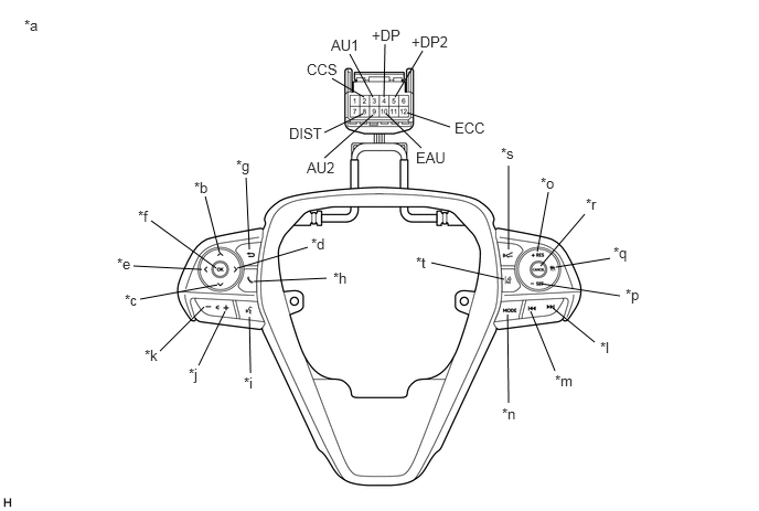
Measure the resistance according to the value(s) in the table below.
2.396,2.656 3.083,2.625
false
2.24,2.531 2.906,2.333
false
2.365,3.521 2.354,2.99
false
1.875,3.448 2.125,2.938
false
1.51,3.313 1.927,2.896
false
2.042,2.531 1.427,2.083
false
1.323,2.823 2.052,2.688
false
1.26,2.51 1.906,2.542
false
2.354,2.354 2.323,1.677
false
2.073,2.385 1.938,1.854
false
5.25,2.521 5.76,2.438
false
5.104,2.51 5.521,2.021
false
5.073,2.375 5.177,1.813
false
4.802,2.354 4.802,1.563
false
5.24,3.5 5.01,2.938
false
5.615,3.229 5.219,2.906
false
5.854,2.792 5.104,2.677
false
4.073,2.479 4.76,2.635
false
4.792,2.969 4.802,3.802
false
3.135,0.74 3.438,0.917
false
3.302,0.51 3.521,0.917
false
3.635,0.417 3.625,0.917
false
3.729,0.917 3.99,0.479
false
3.844,1.063 4.25,1.198
false
3.646,1.073 3.979,1.396
false
3.521,1.083 3.063,1.49
false
3.427,1.073 3.063,1.25
false
2.229,1.479 2.542,1.677
0.313,0.198
10
false
*g
1.833,1.688 2.146,1.885
0.313,0.198
10
false
*b
1.302,1.958 1.615,2.156
0.313,0.198
10
false
*f
1.104,2.406 1.417,2.604
0.313,0.198
10
false
*e
1.177,2.75 1.49,2.948
0.313,0.198
10
false
*c
1.365,3.271 1.677,3.469
0.313,0.198
10
false
*k
1.781,3.448 2.094,3.646
0.313,0.198
10
false
*j
2.302,3.531 2.615,3.729
0.313,0.198
10
false
*i
3.146,2.542 3.458,2.74
0.313,0.198
10
false
*h
2.938,2.219 3.25,2.417
0.313,0.198
10
false
*d
3.927,2.396 4.365,2.604
0.438,0.208
10
false
*t
4.729,1.365 5.229,1.531
0.5,0.167
10
false
*s
5.104,1.646 5.417,1.844
0.313,0.198
10
false
*o
5.531,1.844 5.844,2.042
0.313,0.198
10
false
*r
5.792,2.302 6.104,2.5
0.313,0.198
10
false
*q
5.906,2.698 6.219,2.896
0.313,0.198
10
false
*p
5.667,3.198 5.979,3.396
0.313,0.198
10
false
*l
5.24,3.51 5.552,3.708
0.313,0.198
10
false
*m
4.74,3.823 5.063,4.073
0.323,0.25
10
false
*n
3.51,0.25 3.927,0.469
0.417,0.219
10
false
+DP
3.125,0.344 3.51,0.573
0.385,0.229
10
false
AU1
2.896,0.573 3.385,0.823
0.49,0.25
10
false
CCS
2.729,1.177 3.365,1.385
0.635,0.208
10
false
DIST
2.896,1.5 3.385,1.688
0.49,0.188
10
false
AU2
3.927,1.406 4.396,1.677
0.469,0.271
10
false
EAU
4.292,1.125 4.958,1.354
0.667,0.229
10
false
ECC
3.885,0.313 4.365,0.563
0.479,0.25
10
false
+DP2
0.229,0.156 0.542,0.354
0.313,0.198
10
false
*a
| *a | Component without harness connected
(Steering Pad Switch Assembly) |
*b | Up |
| *c | Down | *d | Right |
| *e | Left | *f | OK |
| *g | Back | *h | On/off Hook |
| *i | Voice | *j | Volume+ |
| *k | Volume- | *l | Seek+ |
| *m | Seek- | *n | MODE |
| *o | +RES | *p | -SET |
| *q | Cruise Control Main | *r | CANCEL |
| *s | Distance Control | *t | Lane Tracing Assist |
- Standard Resistance:
Tester Connection Condition Specified Condition 3 (AU1) - 10 (EAU) No switch pushed 95 to 105 kΩ Seek+ switch pushed Below 2.5 Ω Seek- switch pushed 313 to 345 Ω Volume+ switch pushed 950 to 1050 Ω Volume- switch pushed 2955 to 3265 Ω 9 (AU2) - 10 (EAU) No switch pushed 95 to 105 kΩ MODE switch pushed Below 2.5 Ω On/off hook switch pushed 950 to 1050 Ω Voice switch pushed 2955 to 3265 Ω 5 (+DP2) - 10 (EAU) No switch pushed 95 to 105 kΩ Left switch pushed Below 2.5 Ω Up switch pushed 313 to 345 Ω Down switch pushed 950 to 1050 Ω Right switch pushed 2955 to 3265 Ω 4 (+DP) - 10 (EAU) No switch pushed 95 to 105 kΩ OK switch pushed Below 2.5 Ω Back switch pushed 313 to 345 Ω 8 (DIST) - 12 (ECC) No switch pushed 1 MΩ or higher Distance control switch pushed Below 2.5 Ω Lane tracing assist switch pushed 228 to 252 Ω 2 (CCS) - 12 (ECC) No switch pushed 1 MΩ or higher Cruise control main switch pushed Below 2.5 Ω CANCEL switch pushed 228 to 252 Ω +RES switch pushed 599 to 661 Ω -SET switch pushed 1463 to 1617 Ω
- HINT:
-
If the result is not as specified, replace the steering pad switch assembly.
b.
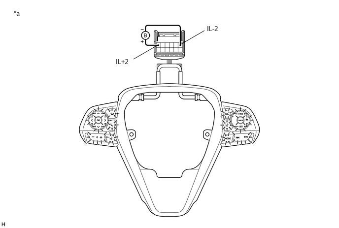
Check the illumination.
2.823,1.25 3.344,0.948
false
3.802,0.948 4.323,0.646
false
0.292,0.198 0.604,0.396
0.313,0.198
10
false
*a
2.448,1.219 3.219,1.417
0.771,0.198
10
false
IL+2
4.375,0.521 5.146,0.719
0.771,0.198
10
false
IL-2
| *a | Component without harness connected
(Steering Pad Switch Assembly) |
- | - |
i.
Connect a positive (+) lead from the auxiliary battery to terminal 1 (IL+2) and a negative (-) lead to terminal 6 (IL-2) of the steering pad switch assembly connector.
ii.
Check that the steering pad switch assembly illumination illuminates.
- OK:
The steering pad switch assembly illumination illuminates.
- HINT:
-
If the result is not as specified, replace the steering pad switch assembly.