LIGHTING (INT) LIGHTING SYSTEM Instrument Panel Illumination does not Turn On
DESCRIPTION
The power distribution box assembly controls the instrument panel illuminations.
WIRING DIAGRAM
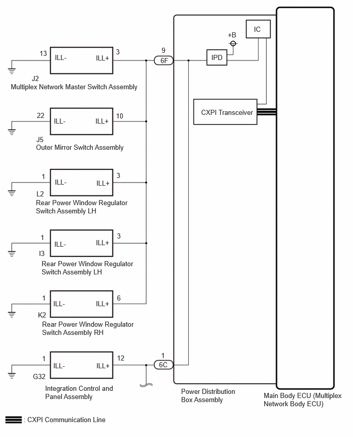
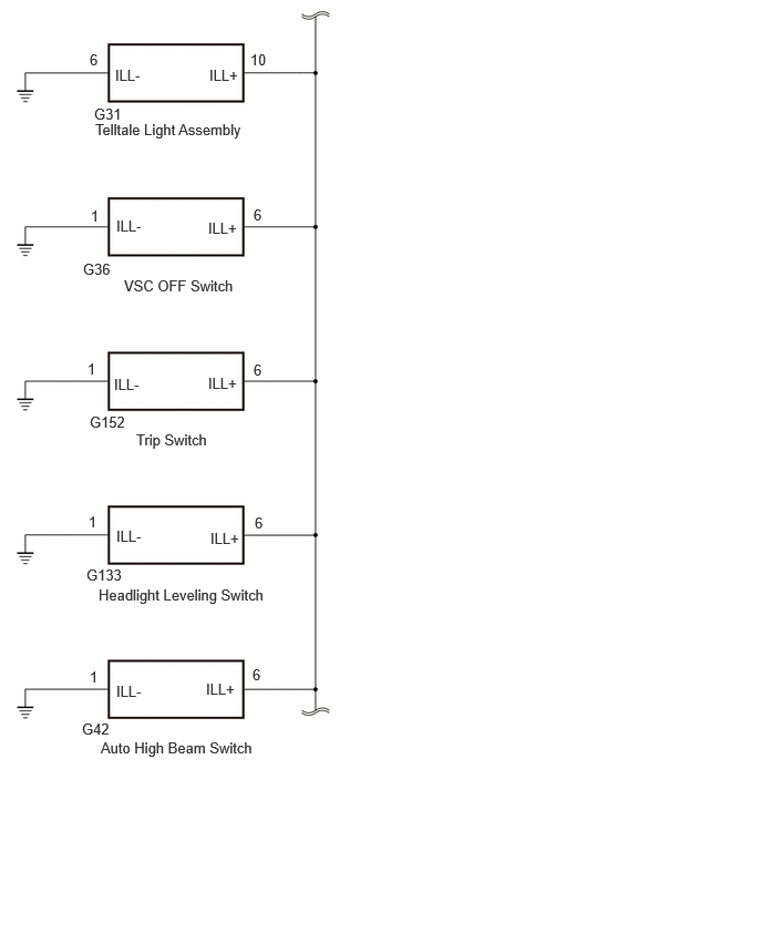
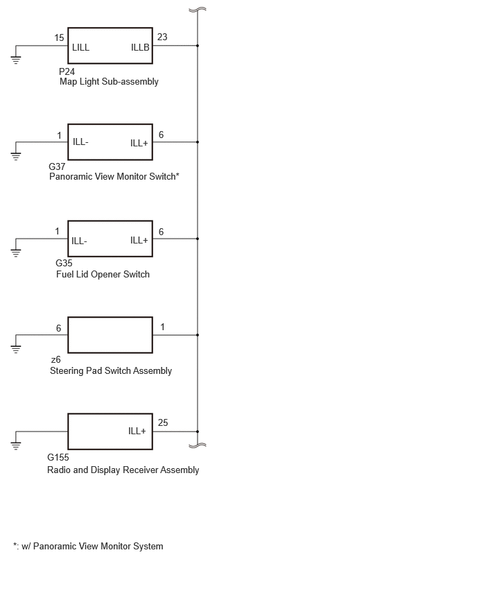
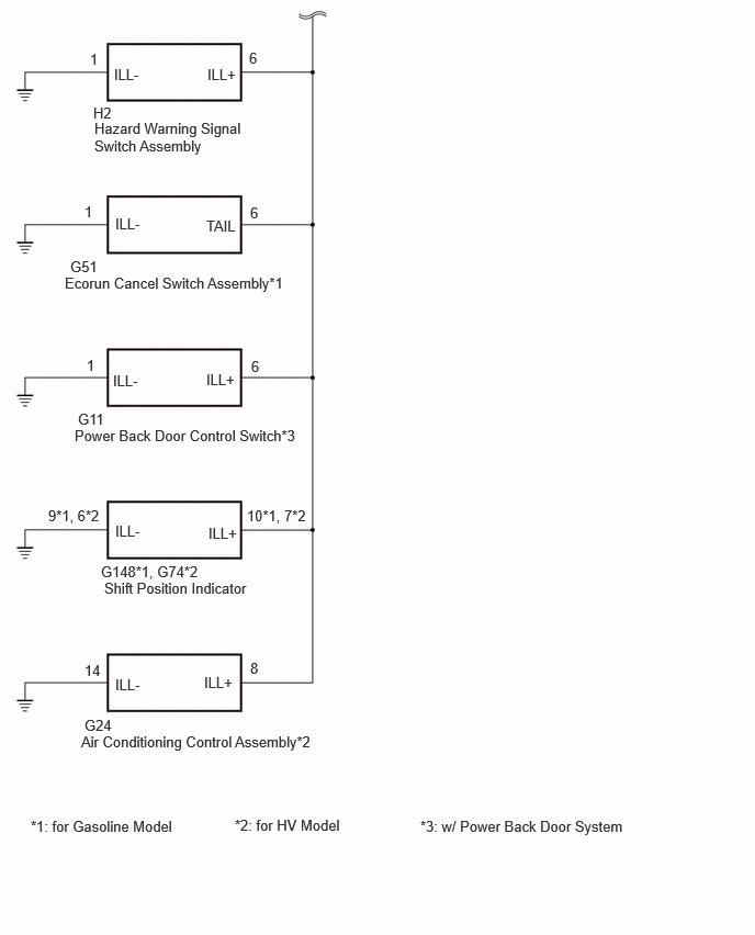
CAUTION / NOTICE / HINT
- NOTICE:
-
First perform the communication function inspections in How to Proceed with Troubleshooting to confirm that there are no CXPI communication malfunctions before troubleshooting this symptom.
PROCEDURE
Read the Data List according to the display on the GTS.
- Body Electrical > Power Distribution Box > Data List
-
Tester Display Measurement Item Range Normal Condition Diagnostic Note Panel Light Input Signal Panel light input condition OFF or ON OFF: Light control switch not in tail position
ON: Light control switch in tail position-
- Body Electrical > Power Distribution Box > Data List
-
Tester Display Panel Light Input Signal - 50003 475 1295
- OK:
The GTS display changes correctly in response to the operation of the light control switch.
- Result:
Proceed to OK NG
OK
NG
Read the Data List according to the display on the GTS.
- Body Electrical > Power Distribution Box > Data List
-
Tester Display Measurement Item Range Normal Condition Diagnostic Note Panel Light Output Signal Panel light output condition OFF or ON OFF: Light control switch not in tail or head position
ON: Light control switch in tail or head position-
- Body Electrical > Power Distribution Box > Data List
-
Tester Display Panel Light Output Signal - 50003 475 1296
- OK:
The GTS display changes correctly in response to the operation of the light control switch.
- Result:
Proceed to OK NG
OK
NG
Turn the light control switch to the TAIL position.
Read the Data List according to the display on the GTS.
- Body Electrical > Power Distribution Box > Data List
-
Tester Display Measurement Item Range Normal Condition Diagnostic Note Panel Light Fuse Shut Off Status Panel light fuse condition OFF or ON OFF: Fuse not shut off
ON: Fuse shut off-
- Body Electrical > Power Distribution Box > Data List
-
Tester Display Panel Light Fuse Shut Off Status - 50003 475 1298
- OK:
The Data List value displays "OFF".
- Result:
Proceed to OK NG
OK
NG
Disconnect the J2 multiplex network master switch assembly connector.
Turn the light control switch to the TAIL position.
Read the Data List according to the display on the GTS.
- Body Electrical > Power Distribution Box > Data List
-
Tester Display Measurement Item Range Normal Condition Diagnostic Note Panel Light Fuse Shut Off Status Panel light fuse condition OFF or ON OFF: Fuse not shut off
ON: Fuse shut off-
- Body Electrical > Power Distribution Box > Data List
-
Tester Display Panel Light Fuse Shut Off Status - 50003 475 1298
- OK:
The Data List value displays "OFF".
- Result:
Proceed to OK NG
OK
NG
Disconnect the J5 outer mirror switch assembly connector.
Turn the light control switch to the TAIL position.
Read the Data List according to the display on the GTS.
- Body Electrical > Power Distribution Box > Data List
-
Tester Display Measurement Item Range Normal Condition Diagnostic Note Panel Light Fuse Shut Off Status Panel light fuse condition OFF or ON OFF: Fuse not shut off
ON: Fuse shut off-
- Body Electrical > Power Distribution Box > Data List
-
Tester Display Panel Light Fuse Shut Off Status - 50003 475 1298
- OK:
The Data List value displays "OFF".
- Result:
Proceed to OK NG
OK
NG
Disconnect the L2 rear power window regulator switch assembly LH connector.
Turn the light control switch to the TAIL position.
Read the Data List according to the display on the GTS.
- Body Electrical > Power Distribution Box > Data List
-
Tester Display Measurement Item Range Normal Condition Diagnostic Note Panel Light Fuse Shut Off Status Panel light fuse condition OFF or ON OFF: Fuse not shut off
ON: Fuse shut off-
- Body Electrical > Power Distribution Box > Data List
-
Tester Display Panel Light Fuse Shut Off Status - 50003 475 1298
- OK:
The Data List value displays "OFF".
- Result:
Proceed to OK NG
OK
NG
Disconnect the I3 power window regulator switch assembly connector.
Turn the light control switch to the TAIL position.
Read the Data List according to the display on the GTS.
- Body Electrical > Power Distribution Box > Data List
-
Tester Display Measurement Item Range Normal Condition Diagnostic Note Panel Light Fuse Shut Off Status Panel light fuse condition OFF or ON OFF: Fuse not shut off
ON: Fuse shut off-
- Body Electrical > Power Distribution Box > Data List
-
Tester Display Panel Light Fuse Shut Off Status - 50003 475 1298
- OK:
The Data List value displays "OFF".
- Result:
Proceed to OK NG
OK
NG
Disconnect the K2 rear power window regulator switch assembly RH connector.
Turn the light control switch to the TAIL position.
Read the Data List according to the display on the GTS.
- Body Electrical > Power Distribution Box > Data List
-
Tester Display Measurement Item Range Normal Condition Diagnostic Note Panel Light Fuse Shut Off Status Panel light fuse condition OFF or ON OFF: Fuse not shut off
ON: Fuse shut off-
- Body Electrical > Power Distribution Box > Data List
-
Tester Display Panel Light Fuse Shut Off Status - 50003 475 1298
- OK:
The Data List value displays "OFF".
- Result:
Proceed to OK NG
OK
NG
Disconnect the G32 integration control and panel assembly connector.
Turn the light control switch to the TAIL position.
Read the Data List according to the display on the GTS.
- Body Electrical > Power Distribution Box > Data List
-
Tester Display Measurement Item Range Normal Condition Diagnostic Note Panel Light Fuse Shut Off Status Panel light fuse condition OFF or ON OFF: Fuse not shut off
ON: Fuse shut off-
- Body Electrical > Power Distribution Box > Data List
-
Tester Display Panel Light Fuse Shut Off Status - 50003 475 1298
- OK:
The Data List value displays "OFF".
- Result:
Proceed to OK NG
OK
NG
Disconnect the G31 telltale light assembly connector.
Turn the light control switch to the TAIL position.
Read the Data List according to the display on the GTS.
- Body Electrical > Power Distribution Box > Data List
-
Tester Display Measurement Item Range Normal Condition Diagnostic Note Panel Light Fuse Shut Off Status Panel light fuse condition OFF or ON OFF: Fuse not shut off
ON: Fuse shut off-
- Body Electrical > Power Distribution Box > Data List
-
Tester Display Panel Light Fuse Shut Off Status - 50003 475 1298
- OK:
The Data List value displays "OFF".
- Result:
Proceed to OK NG
OK
NG
Disconnect the G36 VSC OFF switch connector.
Turn the light control switch to the TAIL position.
Read the Data List according to the display on the GTS.
- Body Electrical > Power Distribution Box > Data List
-
Tester Display Measurement Item Range Normal Condition Diagnostic Note Panel Light Fuse Shut Off Status Panel light fuse condition OFF or ON OFF: Fuse not shut off
ON: Fuse shut off-
- Body Electrical > Power Distribution Box > Data List
-
Tester Display Panel Light Fuse Shut Off Status - 50003 475 1298
- OK:
The Data List value displays "OFF".
- Result:
Proceed to OK NG
OK
NG
Disconnect the G152 trip switch connector.
Turn the light control switch to the TAIL position.
Read the Data List according to the display on the GTS.
- Body Electrical > Power Distribution Box > Data List
-
Tester Display Measurement Item Range Normal Condition Diagnostic Note Panel Light Fuse Shut Off Status Panel light fuse condition OFF or ON OFF: Fuse not shut off
ON: Fuse shut off-
- Body Electrical > Power Distribution Box > Data List
-
Tester Display Panel Light Fuse Shut Off Status - 50003 475 1298
- OK:
The Data List value displays "OFF".
- Result:
Proceed to OK NG
OK
NG
Disconnect the G133 headlight leveling switch connector.
Turn the light control switch to the TAIL position.
Read the Data List according to the display on the GTS.
- Body Electrical > Power Distribution Box > Data List
-
Tester Display Measurement Item Range Normal Condition Diagnostic Note Panel Light Fuse Shut Off Status Panel light fuse condition OFF or ON OFF: Fuse not shut off
ON: Fuse shut off-
- Body Electrical > Power Distribution Box > Data List
-
Tester Display Panel Light Fuse Shut Off Status - 50003 475 1298
- OK:
The Data List value displays "OFF".
- Result:
Proceed to OK NG
OK
NG
Disconnect the G42 auto high beam switch connector.
Turn the light control switch to the TAIL position.
Read the Data List according to the display on the GTS.
- Body Electrical > Power Distribution Box > Data List
-
Tester Display Measurement Item Range Normal Condition Diagnostic Note Panel Light Fuse Shut Off Status Panel light fuse condition OFF or ON OFF: Fuse not shut off
ON: Fuse shut off-
- Body Electrical > Power Distribution Box > Data List
-
Tester Display Panel Light Fuse Shut Off Status - 50003 475 1298
- OK:
The Data List value displays "OFF".
- Result:
Proceed to OK NG
OK
NG
Disconnect the P24 map light sub-assembly connector.
Turn the light control switch to the TAIL position.
Read the Data List according to the display on the GTS.
- Body Electrical > Power Distribution Box > Data List
-
Tester Display Measurement Item Range Normal Condition Diagnostic Note Panel Light Fuse Shut Off Status Panel light fuse condition OFF or ON OFF: Fuse not shut off
ON: Fuse shut off-
- Body Electrical > Power Distribution Box > Data List
-
Tester Display Panel Light Fuse Shut Off Status - 50003 475 1298
- OK:
The Data List value displays "OFF".
- Result:
Proceed to OK NG
OK
NG
- NOTICE:
-
For vehicle without panoramic view monitor system, proceed to next step.
Disconnect the G37 panoramic view monitor switch connector.
Turn the light control switch to the TAIL position.
Read the Data List according to the display on the GTS.
- Body Electrical > Power Distribution Box > Data List
-
Tester Display Measurement Item Range Normal Condition Diagnostic Note Panel Light Fuse Shut Off Status Panel light fuse condition OFF or ON OFF: Fuse not shut off
ON: Fuse shut off-
- Body Electrical > Power Distribution Box > Data List
-
Tester Display Panel Light Fuse Shut Off Status - 50003 475 1298
- OK:
The Data List value displays "OFF".
- Result:
Proceed to OK NG
OK
NG
Disconnect the G35 fuel lid opener switch connector.
Turn the light control switch to the TAIL position.
Read the Data List according to the display on the GTS.
- Body Electrical > Power Distribution Box > Data List
-
Tester Display Measurement Item Range Normal Condition Diagnostic Note Panel Light Fuse Shut Off Status Panel light fuse condition OFF or ON OFF: Fuse not shut off
ON: Fuse shut off-
- Body Electrical > Power Distribution Box > Data List
-
Tester Display Panel Light Fuse Shut Off Status - 50003 475 1298
- OK:
The Data List value displays "OFF".
- Result:
Proceed to OK NG
OK
NG
Disconnect the z6 steering pad switch assembly connector.
Turn the light control switch to the TAIL position.
Read the Data List according to the display on the GTS.
- Body Electrical > Power Distribution Box > Data List
-
Tester Display Measurement Item Range Normal Condition Diagnostic Note Panel Light Fuse Shut Off Status Panel light fuse condition OFF or ON OFF: Fuse not shut off
ON: Fuse shut off-
- Body Electrical > Power Distribution Box > Data List
-
Tester Display Panel Light Fuse Shut Off Status - 50003 475 1298
- OK:
The Data List value displays "OFF".
- Result:
Proceed to OK NG
OK
NG
Disconnect the G155 radio and display receiver assembly connector.
Turn the light control switch to the TAIL position.
Read the Data List according to the display on the GTS.
- Body Electrical > Power Distribution Box > Data List
-
Tester Display Measurement Item Range Normal Condition Diagnostic Note Panel Light Fuse Shut Off Status Panel light fuse condition OFF or ON OFF: Fuse not shut off
ON: Fuse shut off-
- Body Electrical > Power Distribution Box > Data List
-
Tester Display Panel Light Fuse Shut Off Status - 50003 475 1298
- OK:
The Data List value displays "OFF".
- Result:
Proceed to OK NG
OK
NG
Disconnect the H2 hazard warning signal switch assembly connector.
Turn the light control switch to the TAIL position.
Read the Data List according to the display on the GTS.
- Body Electrical > Power Distribution Box > Data List
-
Tester Display Measurement Item Range Normal Condition Diagnostic Note Panel Light Fuse Shut Off Status Panel light fuse condition OFF or ON OFF: Fuse not shut off
ON: Fuse shut off-
- Body Electrical > Power Distribution Box > Data List
-
Tester Display Panel Light Fuse Shut Off Status - 50003 475 1298
- OK:
The Data List value displays "OFF".
- Result:
Proceed to OK NG
OK
NG
- NOTICE:
-
For vehicle without ecorun cancel switch, proceed to next step.
Disconnect the G51 ecorun cancel switch assembly connector.
Turn the light control switch to the TAIL position.
Read the Data List according to the display on the GTS.
- Body Electrical > Power Distribution Box > Data List
-
Tester Display Measurement Item Range Normal Condition Diagnostic Note Panel Light Fuse Shut Off Status Panel light fuse condition OFF or ON OFF: Fuse not shut off
ON: Fuse shut off-
- Body Electrical > Power Distribution Box > Data List
-
Tester Display Panel Light Fuse Shut Off Status - 50003 475 1298
- OK:
The Data List value displays "OFF".
- Result:
Proceed to OK NG
OK
NG
- NOTICE:
-
For vehicle without power back door system, proceed to next step.
Disconnect the G11 power back door control switch connector.
Turn the light control switch to the TAIL position.
Read the Data List according to the display on the GTS.
- Body Electrical > Power Distribution Box > Data List
-
Tester Display Measurement Item Range Normal Condition Diagnostic Note Panel Light Fuse Shut Off Status Panel light fuse condition OFF or ON OFF: Fuse not shut off
ON: Fuse shut off-
- Body Electrical > Power Distribution Box > Data List
-
Tester Display Panel Light Fuse Shut Off Status - 50003 475 1298
- OK:
The Data List value displays "OFF".
- Result:
Proceed to OK NG
OK
NG
*1: for Gasoline Model
*2: for HV Model
Disconnect the G148*1 or G74*2 shift position indicator connector.
Turn the light control switch to the TAIL position.
Read the Data List according to the display on the GTS.
- Body Electrical > Power Distribution Box > Data List
-
Tester Display Measurement Item Range Normal Condition Diagnostic Note Panel Light Fuse Shut Off Status Panel light fuse condition OFF or ON OFF: Fuse not shut off
ON: Fuse shut off-
- Body Electrical > Power Distribution Box > Data List
-
Tester Display Panel Light Fuse Shut Off Status - 50003 475 1298
- OK:
The Data List value displays "OFF".
- Result:
Proceed to OK NG
OK
NG
Disconnect the G24 air conditioning control assembly connector.
Turn the light control switch to the TAIL position.
Read the Data List according to the display on the GTS..
- Body Electrical > Power Distribution Box > Data List
-
Tester Display Measurement Item Range Normal Condition Diagnostic Note Panel Light Fuse Shut Off Status Panel light fuse condition OFF or ON OFF: Fuse not shut off
ON: Fuse shut off-
- Body Electrical > Power Distribution Box > Data List
-
Tester Display Panel Light Fuse Shut Off Status - 50003 475 1298
- OK:
The Data List value displays "OFF".
- Result:
Proceed to OK NG
OK
NG
*1: w/ Power Back Door System
*2: w/ Panoramic View Monitor System
*3: for Gasoline Model
*4: for HV Model
Disconnect the J2 multiplex network master switch assembly connector.
Disconnect the J5 outer mirror switch assembly connector.
Disconnect the L2 rear power window regulator switch assembly LH connector.
Disconnect the I3 power window regulator switch assembly connector.
Disconnect the K2 rear power window regulator switch assembly RH connector.
Disconnect the G32 integration control and panel assembly connector.
Disconnect the G31 telltale light assembly connector.
Disconnect the G36 VSC OFF switch connector.
Disconnect the G152 trip switch connector.
Disconnect the G133 headlight leveling switch connector.
Disconnect the G42 auto high beam switch connector.
Disconnect the P24 map light sub-assembly connector.
Disconnect the G37 panoramic view monitor switch connector.*2
Disconnect the G35 fuel lid opener switch connector.
Disconnect the z6 steering pad switch assembly connector.
Disconnect the G155 radio and display receiver assembly connector.
Disconnect the H2 hazard warning signal switch assembly connector.
Disconnect the G51 ecorun cancel switch assembly connector.*3
Disconnect the G11 power back door control switch connector.*1
Disconnect the G148*3 or G74*4 shift position indicator connector.
Disconnect the G24 air conditioning control assembly connector.*4
Disconnect the 6C and 6F power distribution box assembly connectors.
Measure the resistance according to the value(s) in the table below.
- Standard Resistance:
Tester Connection Condition Specified Condition J5-10 (ILL+) - 6F-9 Always Below 1 Ω G36-6 (ILL+) - 6F-9 Always Below 1 Ω J5-10 (ILL+) or 6F-9 - Body ground Always 10 kΩ or higher G36-6 (ILL+) or 6F-9 - Body ground Always 10 kΩ or higher
- Result:
Proceed to OK NG
OK
NG