RM35X0E _57 Power Source / Network _078518 NETWORKING _0381088 CAN COMMUNICATION SYSTEM J

NETWORKING  CAN COMMUNICATION SYSTEM  Check Bus 1 Line (for RHD)  


DESCRIPTION

Symptom Trouble Area

*1: w/ TOYOTA Parking Assist-sensor System

*2: w/ Pre-collision System

*3: w/ Blind Spot Monitor System

*4: w/ Parking Assist Monitor System

*5: w/ Panoramic View Monitor System

*6: for Wagon

*7: except Wagon

There are ECUs or sensors that display a communication stop on the bus diagnostic screen. Or, there are ECUs or sensors that store a communication stop history on the "Detail" screen.
·

CAN bus lines or connector

·

Central gateway ECU (network gateway ECU)

·

Forward recognition camera*2

·

Millimeter wave radar sensor Assembly*2

·

Parking assist ECU*5

·

Television camera assembly*4

·

Blind spot monitor sensor LH*3

·

Clearance warning ECU assembly*1

·

No. 9 CAN junction connector*6

·

No. 10 CAN junction connector*7

·

No. 12 CAN junction connector

·

No. 3 CAN junction terminal


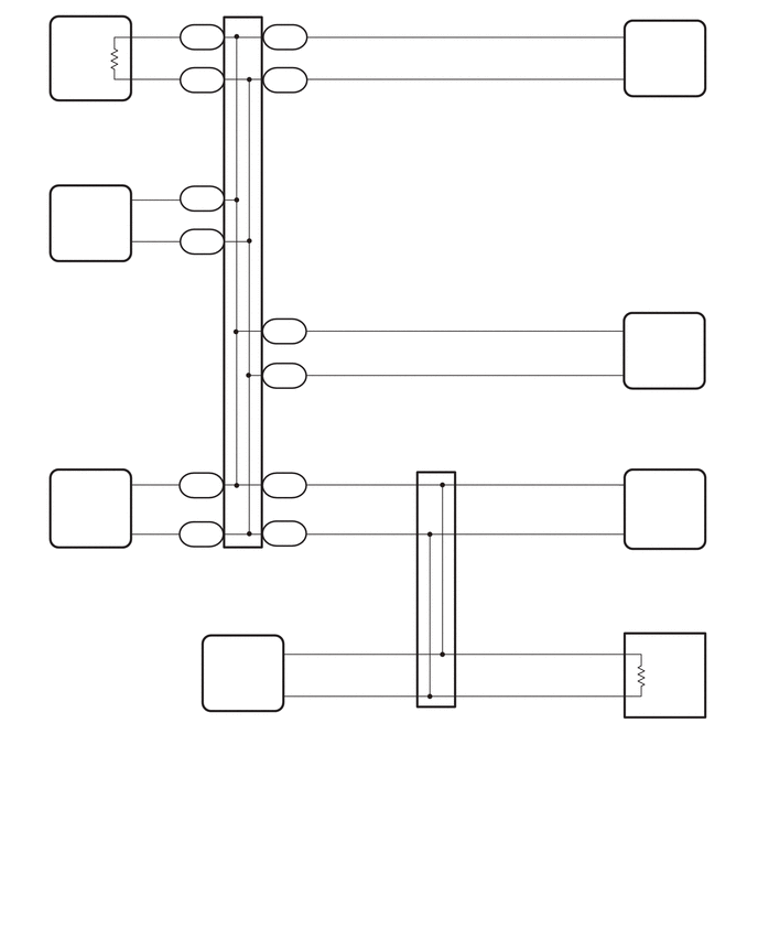
WIRING DIAGRAM

C491474
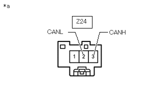
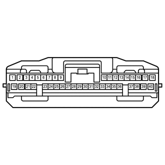
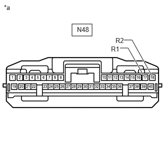
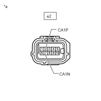
0.073,0.823 0.531,1.021 0.458,0.198 10 false N21 0.063,0.99 2.042,1.354 1.979,0.365 10 false Central Gateway ECU (Network Gateway ECU) 0.813,0.167 1.271,0.365 0.458,0.198 10 false CA1H 0.802,0.76 1.26,0.958 0.458,0.198 10 false CA1L 1.76,0.26 2.219,0.458 0.458,0.198 10 false N222 1.281,0.156 1.531,0.333 0.25,0.177 10 false 23 1.281,0.552 1.531,0.729 0.25,0.177 10 false 8 1.865,0.073 2.115,0.25 0.25,0.177 10 false 1 2.531,0.26 2.99,0.458 0.458,0.198 10 false N224 2.635,0.063 2.885,0.24 0.25,0.177 10 false 1 1.76,0.656 2.219,0.854 0.458,0.198 10 false N222 1.865,0.469 2.115,0.646 0.25,0.177 10 false 2 2.635,0.469 2.885,0.646 0.25,0.177 10 false 2 2.542,0.656 3,0.854 0.458,0.198 10 false N224 0.167,2.323 0.625,2.521 0.458,0.198 10 false A3 0.146,2.5 1.563,2.885 1.417,0.385 10 false Millimeter Wave Radar Sensor Assembly*2 0.813,1.813 1.271,2.01 0.458,0.198 10 false CA2H 0.833,2.156 1.292,2.354 0.458,0.198 10 false CA2L 1.74,1.781 2.198,1.979 0.458,0.198 10 false N226 1.844,1.563 2.094,1.74 0.25,0.177 10 false 1 1.74,2.188 2.198,2.385 0.458,0.198 10 false N226 1.854,1.99 2.104,2.167 0.25,0.177 10 false 2 2.531,3.042 2.99,3.24 0.458,0.198 10 false N223 5.677,0.146 5.927,0.323 0.25,0.177 10 false 40 5.667,0.542 5.917,0.719 0.25,0.177 10 false 18 5.958,0.271 6.417,0.469 0.458,0.198 10 false CANH 5.958,0.635 6.417,0.833 0.458,0.198 10 false CANL 5.427,0.833 5.885,1.031 0.458,0.198 10 false N151 5.427,1.031 6.833,1.24 1.406,0.208 10 false Parking Assist ECU*5 2.635,2.833 2.885,3.01 0.25,0.177 10 false 1 2.635,3.25 2.885,3.427 0.25,0.177 10 false 2 2.521,3.458 2.979,3.656 0.458,0.198 10 false N223 5.677,2.927 5.927,3.104 0.25,0.177 10 false 17 5.677,3.344 5.927,3.521 0.25,0.177 10 false 18 5.958,3.052 6.417,3.25 0.458,0.198 10 false R1 5.958,3.406 6.417,3.604 0.458,0.198 10 false R2 5.531,3.594 5.99,3.792 0.458,0.198 10 false N48 5.521,3.75 6.74,4.115 1.219,0.365 10 false Clearance Warning ECU Assembly*1 0.802,4.521 1.26,4.719 0.458,0.198 10 false CA1P 0.823,4.906 1.281,5.104 0.458,0.198 10 false CA1N 1.74,4.51 2.198,4.708 0.458,0.198 10 false N227 1.833,4.292 2.083,4.469 0.25,0.177 10 false 1 1.729,4.948 2.188,5.146 0.458,0.198 10 false N227 1.854,4.74 2.104,4.917 0.25,0.177 10 false 2 2.531,4.49 2.99,4.688 0.458,0.198 10 false N225 2.531,4.938 2.99,5.135 0.458,0.198 10 false N225 2.594,4.292 2.844,4.469 0.25,0.177 10 false 1 2.594,4.74 2.844,4.917 0.25,0.177 10 false 2 3.729,4.385 3.979,4.563 0.25,0.177 10 false 11 4.354,4.375 4.604,4.552 0.25,0.177 10 false 9 4.375,4.844 4.625,5.021 0.25,0.177 10 false 20 3.708,4.865 3.958,5.042 0.25,0.177 10 false 22 5.729,4.396 5.979,4.573 0.25,0.177 10 false 2 5.729,4.844 5.979,5.021 0.25,0.177 10 false 7 5.958,4.5 6.417,4.698 0.458,0.198 10 false CA1P 5.958,4.938 6.417,5.135 0.458,0.198 10 false CA1N 5.604,5.094 6.063,5.292 0.458,0.198 10 false e2 5.604,5.25 6.823,5.615 1.219,0.365 10 false Blind Spot Monitor Sensor LH*3 2.229,6.104 2.688,6.302 0.458,0.198 10 false CANH 2.24,6.458 2.698,6.656 0.458,0.198 10 false CANL 3.396,6 3.979,6.177 0.583,0.177 10 false 8*6, 7*7 2.74,5.979 2.99,6.156 0.25,0.177 10 false 4 2.74,6.354 2.99,6.531 0.25,0.177 10 false 1 3.25,6.385 3.979,6.542 0.729,0.156 10 false 19*6, 18*7 0.135,5.083 0.594,5.281 0.458,0.198 10 false a9 0.135,5.25 1.427,5.615 1.292,0.365 10 false Forward Recognition Camera*2 1.667,5.219 2.917,5.583 1.25,0.365 10 false No. 9 CAN Junction Connector 1.74,6.917 2.906,7.281 1.167,0.365 10 false Television Camera Assembly*4 1.74,6.74 2.438,6.927 0.698,0.188 10 false i7*6, k9*7 3.552,6.656 4.25,6.844 0.698,0.188 10 false Z31 3.542,6.833 4.854,7.208 1.313,0.375 10 false No. 12 CAN Junction Connector 4.365,5.99 4.615,6.167 0.25,0.177 10 false 10 4.365,6.375 4.615,6.552 0.25,0.177 10 false 21 5.979,6 6.438,6.198 0.458,0.198 10 false CANH 5.958,6.583 6.417,6.781 0.458,0.198 10 false CANL 5.74,6 5.99,6.177 0.25,0.177 10 false 3 5.74,6.385 5.99,6.563 0.25,0.177 10 false 2 5.615,6.719 6.073,6.917 0.458,0.198 10 false Z24 5.635,6.875 6.896,7.25 1.26,0.375 10 false No. 3 CAN Junction Terminal 0.115,7.698 3.198,7.896 3.083,0.198 10 false *1: w/ TOYOTA Parking Assist-sensor System 0.115,8.063 3.146,8.24 3.031,0.177 10 false *2: w/ Pre-collision System 0.115,8.427 3.146,8.604 3.031,0.177 10 false *3: w/ Blind Spot Monitor System 3.188,7.708 5.708,7.917 2.521,0.208 10 false *4: w/ Parking Assist Monitor System 2.74,8.083 5.771,8.26 3.031,0.177 10 false *5: w/ Panoramic View Monitor System 2.719,8.427 4.938,8.604 2.219,0.177 10 false *6: except Double Swing Out Type 5.073,8.427 7.021,8.615 1.948,0.188 10 false *7: for Double Swing Out Type 1.281,1.698 1.531,1.875 0.25,0.177 10 false 3 1.292,2.073 1.542,2.25 0.25,0.177 10 false 2 1.281,4.844 1.531,5.021 0.25,0.177 10 false 11 1.302,4.396 1.552,4.573 0.25,0.177 10 false 5

CAUTION / NOTICE / HINT

CAUTION:

When performing the confirmation driving pattern, obey all speed limits and traffic laws.


NOTICE:
·

Because the order of diagnosis is important to allow correct diagnosis, make sure to begin troubleshooting using How to Proceed with Troubleshooting when CAN communication system related DTCs are output.

Click herePower Source / Network>NETWORKING>CAN COMMUNICATION SYSTEM>HOW TO PROCEED WITH TROUBLESHOOTING

·

Before measuring the resistance of the CAN bus, turn the ignition switch off and leave the vehicle for 1 minute or more without operating the key or any switches, or opening or closing the doors. After that, disconnect the cable from the negative (-) battery terminal and leave the vehicle for 10 minutes or more before measuring the resistance.

·

After the ignition switch is turned off, there may be a waiting time before disconnecting the negative (-) battery terminal.

Click hereGeneral>SETUP>WHEN DISCONNECTING OR RECONNECTING BATTERY TERMINAL>BEFORE DISCONNECTING BATTERY

·

When disconnecting and reconnecting the battery.

Click hereGeneral>SETUP>WHEN DISCONNECTING OR RECONNECTING BATTERY TERMINAL>WORK PROCEDURE

HINT:

When disconnecting and reconnecting the battery, there is an automatic learning function that completes learning when the respective system is used.

Click hereGeneral>SETUP>WHEN DISCONNECTING OR RECONNECTING BATTERY TERMINAL>AUTOMATIC LEARNING CHART


·

Some parts must be initialized and set when replacing or removing and installing parts.

Click hereGeneral>SETUP>WHEN REPLACING OR REMOVING/INSTALLING PARTS>WORK PROCEDURE

·

After performing repairs, perform the DTC check procedure and confirm that the DTCs are not output again.

DTC check procedure: Turn the ignition switch to ON and wait for 1 minute or more. Then operate the suspected malfunctioning system and drive the vehicle at 60 km/h (37 mph) or more for 5 minutes or more.

·

After the repair, perform the CAN bus check and check that all the ECUs and sensors connected to the CAN communication system are displayed as normal.

Click herePower Source / Network>NETWORKING>CAN COMMUNICATION SYSTEM>DIAGNOSIS SYSTEM


HINT:
·

Before disconnecting related connectors for inspection, push in on each connector body to check that the connector is not loose or disconnected.

·

When a connector is disconnected, check that the terminals and connector body are not cracked, deformed or corroded.


PROCEDURE

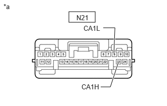
1.CHECK FOR OPEN IN CAN BUS WIRE
NOTICE:

Before measuring the resistance of the CAN bus, turn the ignition switch off and leave the vehicle for 1 minute or more without operating the key or any switches, or opening or closing the doors. After that, disconnect the cable from the negative (-) battery terminal and leave the vehicle for 10 minutes or more before measuring the resistance.


HINT:

Operating the ignition switch, any other switches or door triggers related ECU and sensor communication on the CAN. This communication will cause the resistance value to change.


a.

Disconnect the cable from the negative (-) battery terminal.

b.
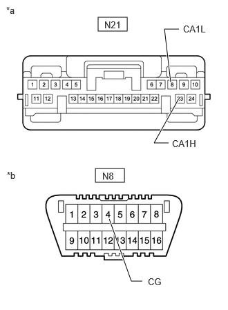
C368243C48
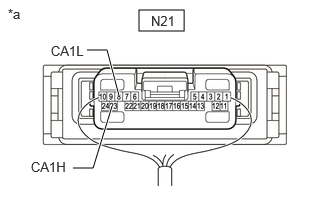
1.448,0.104 1.917,0.323 0.469,0.219 0.76,1.75 0.969,1.75 0.969,1.75 1.167,1.104 true 0.906,0.521 1.115,0.521 1.115,0.521 1.24,1 true 0.323,1.656 0.781,1.854 0.458,0.198 10 false CA1H 1.573,0.135 2.031,0.333 0.458,0.198 10 false N21 0.531,0.448 0.99,0.646 0.458,0.198 10 false CA1L 0.083,0.063 0.542,0.26 0.458,0.198 10 false *a
*a Component with harness connected
(Central Gateway ECU [Network Gateway ECU])


Measure the resistance according to the value(s) in the table below.

Standard Resistance:
Tester Connection Condition Specified Condition
N21-23 (CA1H) - N21-8 (CA1L) Cable disconnected from negative (-) battery terminal Below 70 Ω


Result:
Proceed to
OK
NG


OK

2.CHECK FOR SHORT IN CAN BUS WIRES

NG

74.CHECK FOR OPEN IN CAN BUS WIRE (CENTRAL GATEWAY ECU [NETWORK GATEWAY ECU] - NO. 9 CAN JUNCTION CONNECTOR)
2.CHECK FOR SHORT IN CAN BUS WIRES
a.
C368243C48
1.448,0.104 1.917,0.323 0.469,0.219 0.76,1.75 0.969,1.75 0.969,1.75 1.167,1.104 true 0.906,0.521 1.115,0.521 1.115,0.521 1.24,1 true 0.323,1.656 0.781,1.854 0.458,0.198 10 false CA1H 1.573,0.135 2.031,0.333 0.458,0.198 10 false N21 0.531,0.448 0.99,0.646 0.458,0.198 10 false CA1L 0.083,0.063 0.542,0.26 0.458,0.198 10 false *a
*a Component with harness connected
(Central Gateway ECU [Network Gateway ECU])


Measure the resistance according to the value(s) in the table below.

Standard Resistance:
Tester Connection Condition Specified Condition
N21-23 (CA1H) - N21-8 (CA1L) Cable disconnected from negative (-) battery terminal 54 Ω or higher


Result:
Proceed to
OK
NG


OK

3.CHECK FOR SHORT TO B+ IN CAN BUS WIRE

NG

51.CHECK FOR SHORT IN CAN BUS WIRES (CENTRAL GATEWAY ECU [NETWORK GATEWAY ECU] - NO. 9 CAN JUNCTION CONNECTOR)
3.CHECK FOR SHORT TO B+ IN CAN BUS WIRE
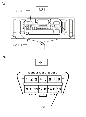
a.
C324419C60
1.448,0.25 1.917,0.51 0.469,0.26 1.427,2.365 1.896,2.625 0.469,0.26 1.25,1.021 1.198,0.427 1.198,0.427 1.031,0.427 true 2.365,3.604 2.031,4.271 2.031,4.271 1.865,4.271 true 1.167,1.146 1.073,1.771 1.073,1.771 0.906,1.771 true 0.063,0.052 0.375,0.25 0.313,0.198 10 false *a 0.115,2.198 0.427,2.396 0.313,0.198 10 false *b 1.552,0.302 2.042,0.552 0.49,0.25 10 false N21 1.531,2.417 2.021,2.667 0.49,0.25 10 false N8 0.635,0.354 1.125,0.604 0.49,0.25 10 false CA1L 1.573,4.188 2.063,4.438 0.49,0.25 10 false BAT 0.51,1.708 1,1.958 0.49,0.25 10 false CA1H
*a Component with harness connected
(Central Gateway ECU [Network Gateway ECU])
*b Front view of DLC3


Measure the resistance according to the value(s) in the table below.

Standard Resistance:
Tester Connection Condition Specified Condition
N21-23 (CA1H) - N8-16 (BAT) Cable disconnected from negative (-) battery terminal 6 kΩ or higher
N21-8 (CA1L) - N8-16 (BAT)


Result:
Proceed to
OK
NG


OK

4.CHECK FOR SHORT TO GND IN CAN BUS WIRE

NG

28.CHECK FOR SHORT TO B+ IN CAN BUS WIRE (CENTRAL GATEWAY ECU [NETWORK GATEWAY ECU] - NO. 9 CAN JUNCTION CONNECTOR)
4.CHECK FOR SHORT TO GND IN CAN BUS WIRE
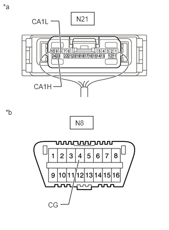
a.
C324419C61
1.448,0.25 1.917,0.51 0.469,0.26 1.427,2.365 1.896,2.625 0.469,0.26 1.24,1.042 1.198,0.427 1.198,0.427 1.031,0.427 true 1.604,3.25 1.396,4.156 1.396,4.156 1.229,4.156 true 1.177,1.135 1.25,1.76 1.25,1.76 1.083,1.76 true 0.063,0.052 0.375,0.25 0.313,0.198 10 false *a 0.115,2.198 0.427,2.396 0.313,0.198 10 false *b 1.552,0.302 2.042,0.552 0.49,0.25 10 false N21 1.531,2.417 2.021,2.667 0.49,0.25 10 false N8 0.646,0.354 1.135,0.604 0.49,0.25 10 false CA1L 0.979,4.083 1.469,4.333 0.49,0.25 10 false CG 0.688,1.677 1.177,1.927 0.49,0.25 10 false CA1H
*a Component with harness connected
(Central Gateway ECU [Network Gateway ECU])
*b Front view of DLC3


Measure the resistance according to the value(s) in the table below.

Standard Resistance:
Tester Connection Condition Specified Condition
N21-23 (CA1H) - N8-4 (CG) Cable disconnected from negative (-) battery terminal 200 Ω or higher
N21-8 (CA1L) - N8-4 (CG)


Result:
Proceed to
OK
NG


OK

NG

5.CHECK FOR SHORT TO GND IN CAN BUS WIRE (CENTRAL GATEWAY ECU [NETWORK GATEWAY ECU] - NO. 9 CAN JUNCTION CONNECTOR)
a.
C414215C07
1.479,0.26 1.917,0.469 0.438,0.208 1.438,2.542 1.875,2.75 0.438,0.208 2.698,0.438 2.479,0.438 2.479,0.438 2.573,1.24 true 2.146,4.24 1.979,4.24 1.979,4.24 1.646,3.302 true 2.542,2.156 2.323,2.156 2.323,2.156 2.688,1.5 true 1.573,0.292 2.188,0.49 0.615,0.198 10 false N21 1.542,2.573 2.156,2.771 0.615,0.198 10 false N8 0.094,0.073 0.708,0.271 0.615,0.198 10 false *a 0.104,2.563 0.719,2.76 0.615,0.198 10 false *b 2.76,0.354 3.292,0.563 0.531,0.208 10 false CA1L 2.229,4.167 2.844,4.365 0.615,0.198 10 false CG 2.594,2.083 3.125,2.292 0.531,0.208 10 false CA1H
*a Front view of wire harness connector
(to Central Gateway ECU [Network Gateway ECU])
*b Front view of DLC3


Disconnect the N21 central gateway ECU (network gateway ECU) connector.


b.

Measure the resistance according to the value(s) in the table below.

Standard Resistance:
Tester Connection Condition Specified Condition
N21-23 (CA1H) - N8-4 (CG) Cable disconnected from negative (-) battery terminal 200 Ω or higher
N21-8 (CA1L) - N8-4 (CG)


c.

Reconnect the N21 central gateway ECU (network gateway ECU) connector.


Result:
Proceed to
OK
NG


OK

NG

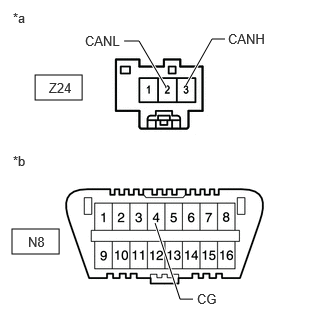
6.CHECK FOR SHORT TO GND IN CAN BUS WIRE (NO. 3 CAN JUNCTION TERMINAL - NO. 12 CAN JUNCTION CONNECTOR)
a.
C414349C03
0.365,0.781 0.854,1.042 0.49,0.26 0.125,2.385 0.615,2.646 0.49,0.26 1.615,2.323 1.875,3.115 1.875,3.115 2.01,3.115 true 1.938,0.885 2.208,0.406 2.208,0.406 2.344,0.406 true 1.292,0.427 1.448,0.427 1.448,0.427 1.729,0.906 true 0.51,0.833 1.125,1.031 0.615,0.198 10 false Z24 0.292,2.438 0.906,2.635 0.615,0.198 10 false N8 2.052,3.031 2.365,3.229 0.313,0.198 10 false CG 2.375,0.323 2.99,0.521 0.615,0.198 10 false CANH 0.885,0.344 1.5,0.542 0.615,0.198 10 false CANL 0.135,0.104 0.448,0.302 0.313,0.198 10 false *a 0.135,1.594 0.448,1.792 0.313,0.198 10 false *b
*a Front view of wire harness connector
(to No. 3 CAN Junction Terminal)
*b Front view of DLC3


Disconnect the Z24 No. 3 CAN junction terminal connector.


b.

Measure the resistance according to the value(s) in the table below.

Standard Resistance:
Tester Connection Condition Specified Condition
Z24-3 (CANH) - N8-4 (CG) Cable disconnected from negative (-) battery terminal 200 Ω or higher
Z24-2 (CANL) - N8-4 (CG)


c.

Reconnect the Z24 No. 3 CAN junction terminal connector.


Result:
Proceed to
OK
NG


OK

REPLACE NO. 3 CAN JUNCTION TERMINAL

NG

7.CHECK FOR SHORT TO GND IN CAN BUS WIRE (NO. 9 CAN JUNCTION CONNECTOR - CENTRAL GATEWAY ECU [NETWORK GATEWAY ECU])
HINT:
·

Distinguish between the connectors connected to the No. 9 CAN junction connector by checking the color of the communication wire.

·

Before disconnecting the connectors, make a note of where it is connected.

·

Reconnect the connector to its original position.


a.

Disconnect the N222 No. 9 CAN junction connector.
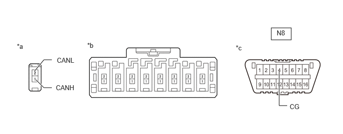
C421483C43
5.667,0.583 6.083,0.833 0.417,0.25 0.75,1.667 0.917,1.833 0.917,1.833 1.083,1.833 true 0.719,1.49 0.917,1.25 0.917,1.25 1.083,1.25 true 5.833,1.5 5.833,2.208 5.833,2.208 6,2.208 true 1.823,0.865 2.135,1.063 0.313,0.198 10 false *b 0.354,0.885 0.667,1.083 0.313,0.198 10 false *a 5.781,0.604 6.385,0.813 0.604,0.208 10 false N8 1.188,1.177 1.698,1.385 0.51,0.208 10 false CANL 4.927,0.917 5.24,1.115 0.313,0.198 10 false *c 1.167,1.75 1.677,1.958 0.51,0.208 10 false CANH 6.052,2.146 6.625,2.354 0.573,0.208 10 false CG
*a Vehicle wire harness connector connected to CAN junction connector *b Rear view of wire harness connector
(to No. 9 CAN Junction Connector)
*c Front view of DLC3 - -


b.

Measure the resistance according to the value(s) in the table below.
Standard Resistance:
Tester Connection Wiring Color Condition Specified Condition Connect to
N222-1 (CANH) - N8-4 (CG) G - W-B Cable disconnected from negative (-) battery terminal 200 Ω or higher Central gateway ECU (network gateway ECU)
N222-2 (CANL) - N8-4 (CG) W - W-B


Result:
Proceed to
OK
NG


OK

8.CHECK VEHICLE TYPE

NG

REPAIR OR REPLACE CAN BUS WIRE OR CONNECTOR (NO. 9 CAN JUNCTION CONNECTOR - CENTRAL GATEWAY ECU [NETWORK GATEWAY ECU])

8.CHECK VEHICLE TYPE
a.

Check for vehicle type.


Result:
Result Proceed to
w/ Panoramic View Monitor System A
w/o Panoramic View Monitor System B


A

9.CHECK FOR SHORT TO GND IN CAN BUS WIRE (NO. 9 CAN JUNCTION CONNECTOR - PARKING ASSIST ECU)

B

10.CHECK VEHICLE TYPE
9.CHECK FOR SHORT TO GND IN CAN BUS WIRE (NO. 9 CAN JUNCTION CONNECTOR - PARKING ASSIST ECU)
HINT:
·

Distinguish between the connectors connected to the No. 9 CAN junction connector by checking the color of the communication wire.

·

Before disconnecting the connectors, make a note of where it is connected.

·

Reconnect the connector to its original position.


a.

Disconnect the N224 No. 9 CAN junction connector.

C421483C43
5.667,0.583 6.083,0.833 0.417,0.25 0.75,1.667 0.917,1.833 0.917,1.833 1.083,1.833 true 0.719,1.49 0.917,1.25 0.917,1.25 1.083,1.25 true 5.833,1.5 5.833,2.208 5.833,2.208 6,2.208 true 1.823,0.865 2.135,1.063 0.313,0.198 10 false *b 0.354,0.885 0.667,1.083 0.313,0.198 10 false *a 5.781,0.604 6.385,0.813 0.604,0.208 10 false N8 1.188,1.177 1.698,1.385 0.51,0.208 10 false CANL 4.927,0.917 5.24,1.115 0.313,0.198 10 false *c 1.167,1.75 1.677,1.958 0.51,0.208 10 false CANH 6.052,2.146 6.625,2.354 0.573,0.208 10 false CG
*a Vehicle wire harness connector connected to CAN junction connector *b Rear view of wire harness connector
(to No. 9 CAN Junction Connector)
*c Front view of DLC3 - -


b.

Measure the resistance according to the value(s) in the table below.
Standard Resistance:
Tester Connection Wiring Color Condition Specified Condition Connect to
N224-1 (CANH) - N8-4 (CG) P - W-B Cable disconnected from negative (-) battery terminal 200 Ω or higher Parking assist ECU
N224-2 (CANL) - N8-4 (CG) W - W-B


Result:
Proceed to
OK
NG


OK

10.CHECK VEHICLE TYPE

NG

22.CHECK FOR SHORT TO GND IN CAN BUS WIRE (PARKING ASSIST ECU - NO. 9 CAN JUNCTION CONNECTOR)
10.CHECK VEHICLE TYPE
a.

Check for vehicle type.


Result:
Result Proceed to
w/ Pre-collision System A
w/o Pre-collision System B


A

11.CHECK FOR SHORT TO GND IN CAN BUS WIRE (NO. 9 CAN JUNCTION CONNECTOR - MILLIMETER WAVE RADAR SENSOR ASSEMBLY)

B

13.CHECK VEHICLE TYPE
11.CHECK FOR SHORT TO GND IN CAN BUS WIRE (NO. 9 CAN JUNCTION CONNECTOR - MILLIMETER WAVE RADAR SENSOR ASSEMBLY)
HINT:
·

Distinguish between the connectors connected to the No. 9 CAN junction connector by checking the color of the communication wire.

·

Before disconnecting the connectors, make a note of where it is connected.

·

Reconnect the connector to its original position.


a.

Disconnect the N226 No. 9 CAN junction connector.

C421483C43
5.667,0.583 6.083,0.833 0.417,0.25 0.75,1.667 0.917,1.833 0.917,1.833 1.083,1.833 true 0.719,1.49 0.917,1.25 0.917,1.25 1.083,1.25 true 5.833,1.5 5.833,2.208 5.833,2.208 6,2.208 true 1.823,0.865 2.135,1.063 0.313,0.198 10 false *b 0.354,0.885 0.667,1.083 0.313,0.198 10 false *a 5.781,0.604 6.385,0.813 0.604,0.208 10 false N8 1.188,1.177 1.698,1.385 0.51,0.208 10 false CANL 4.927,0.917 5.24,1.115 0.313,0.198 10 false *c 1.167,1.75 1.677,1.958 0.51,0.208 10 false CANH 6.052,2.146 6.625,2.354 0.573,0.208 10 false CG
*a Vehicle wire harness connector connected to CAN junction connector *b Rear view of wire harness connector
(to No. 9 CAN Junction Connector)
*c Front view of DLC3 - -


b.

Measure the resistance according to the value(s) in the table below.
Standard Resistance:
Tester Connection Wiring Color Condition Specified Condition Connect to
N226-1 (CANH) - N8-4 (CG) R - W-B Cable disconnected from negative (-) battery terminal 200 Ω or higher Millimeter wave radar sensor assembly
N226-2 (CANL) - N8-4 (CG) W - W-B


Result:
Proceed to
OK
NG


OK

12.CHECK FOR SHORT TO GND IN CAN BUS WIRE (NO. 9 CAN JUNCTION CONNECTOR - FORWARD RECOGNITION CAMERA)

NG

23.CHECK FOR SHORT TO GND IN CAN BUS WIRE (MILLIMETER WAVE RADAR SENSOR ASSEMBLY - NO. 9 CAN JUNCTION CONNECTOR)
12.CHECK FOR SHORT TO GND IN CAN BUS WIRE (NO. 9 CAN JUNCTION CONNECTOR - FORWARD RECOGNITION CAMERA)
HINT:
·

Distinguish between the connectors connected to the No. 9 CAN junction connector by checking the color of the communication wire.

·

Before disconnecting the connectors, make a note of where it is connected.

·

Reconnect the connector to its original position.


a.

Disconnect the N227 No. 9 CAN junction connector.

C421483C43
5.667,0.583 6.083,0.833 0.417,0.25 0.75,1.667 0.917,1.833 0.917,1.833 1.083,1.833 true 0.719,1.49 0.917,1.25 0.917,1.25 1.083,1.25 true 5.833,1.5 5.833,2.208 5.833,2.208 6,2.208 true 1.823,0.865 2.135,1.063 0.313,0.198 10 false *b 0.354,0.885 0.667,1.083 0.313,0.198 10 false *a 5.781,0.604 6.385,0.813 0.604,0.208 10 false N8 1.188,1.177 1.698,1.385 0.51,0.208 10 false CANL 4.927,0.917 5.24,1.115 0.313,0.198 10 false *c 1.167,1.75 1.677,1.958 0.51,0.208 10 false CANH 6.052,2.146 6.625,2.354 0.573,0.208 10 false CG
*a Vehicle wire harness connector connected to CAN junction connector *b Rear view of wire harness connector
(to No. 9 CAN Junction Connector)
*c Front view of DLC3 - -


b.

Measure the resistance according to the value(s) in the table below.
Standard Resistance:
Tester Connection Wiring Color Condition Specified Condition Connect to
N227-1 (CANH) - N8-4 (CG) V - W-B Cable disconnected from negative (-) battery terminal 200 Ω or higher Forward recognition camera
N227-2 (CANL) - N8-4 (CG) W - W-B


Result:
Proceed to
OK
NG


OK

13.CHECK VEHICLE TYPE

NG

24.CHECK FOR SHORT TO GND IN CAN BUS WIRE (FORWARD RECOGNITION CAMERA - NO. 9 CAN JUNCTION CONNECTOR)
13.CHECK VEHICLE TYPE
a.

Check for vehicle type.


Result:
Result Proceed to
w/ TOYOTA Parking Assist-sensor System A
w/o TOYOTA Parking Assist-sensor System B


A

14.CHECK FOR SHORT TO GND IN CAN BUS WIRE (NO. 9 CAN JUNCTION CONNECTOR - CLEARANCE WARNING ECU ASSEMBLY)

B

15.CHECK FOR SHORT TO GND IN CAN BUS WIRE (NO. 9 CAN JUNCTION CONNECTOR - NO. 12 CAN JUNCTION CONNECTOR)
14.CHECK FOR SHORT TO GND IN CAN BUS WIRE (NO. 9 CAN JUNCTION CONNECTOR - CLEARANCE WARNING ECU ASSEMBLY)
HINT:
·

Distinguish between the connectors connected to the No. 9 CAN junction connector by checking the color of the communication wire.

·

Before disconnecting the connectors, make a note of where it is connected.

·

Reconnect the connector to its original position.


a.

Disconnect the N223 No. 9 CAN junction connector.

C421483C43
5.667,0.583 6.083,0.833 0.417,0.25 0.75,1.667 0.917,1.833 0.917,1.833 1.083,1.833 true 0.719,1.49 0.917,1.25 0.917,1.25 1.083,1.25 true 5.833,1.5 5.833,2.208 5.833,2.208 6,2.208 true 1.823,0.865 2.135,1.063 0.313,0.198 10 false *b 0.354,0.885 0.667,1.083 0.313,0.198 10 false *a 5.781,0.604 6.385,0.813 0.604,0.208 10 false N8 1.188,1.177 1.698,1.385 0.51,0.208 10 false CANL 4.927,0.917 5.24,1.115 0.313,0.198 10 false *c 1.167,1.75 1.677,1.958 0.51,0.208 10 false CANH 6.052,2.146 6.625,2.354 0.573,0.208 10 false CG
*a Vehicle wire harness connector connected to CAN junction connector *b Rear view of wire harness connector
(to No. 9 CAN Junction Connector)
*c Front view of DLC3 - -


b.

Measure the resistance according to the value(s) in the table below.

Standard Resistance:
Tester Connection Wiring Color Condition Specified Condition Connect to
N223-1 (CANH) - N8-4 (CG) L - W-B Cable disconnected from negative (-) battery terminal 200 Ω or higher Clearance warning ECU assembly
N223-2 - N8-4 (CG) W - W-B


Result:
Proceed to
OK
NG


OK

15.CHECK FOR SHORT TO GND IN CAN BUS WIRE (NO. 9 CAN JUNCTION CONNECTOR - NO. 12 CAN JUNCTION CONNECTOR)

NG

25.CHECK FOR SHORT TO GND IN CAN BUS WIRE (CLEARANCE WARNING ECU ASSEMBLY - NO. 9 CAN JUNCTION CONNECTOR)
15.CHECK FOR SHORT TO GND IN CAN BUS WIRE (NO. 9 CAN JUNCTION CONNECTOR - NO. 12 CAN JUNCTION CONNECTOR)
HINT:
·

Distinguish between the connectors connected to the No. 9 CAN junction connector by checking the color of the communication wire.

·

Before disconnecting the connectors, make a note of where it is connected.

·

Reconnect the connector to its original position.


a.

Disconnect the N225 No. 9 CAN junction connector.

C421483C43
5.667,0.583 6.083,0.833 0.417,0.25 0.75,1.667 0.917,1.833 0.917,1.833 1.083,1.833 true 0.719,1.49 0.917,1.25 0.917,1.25 1.083,1.25 true 5.833,1.5 5.833,2.208 5.833,2.208 6,2.208 true 1.823,0.865 2.135,1.063 0.313,0.198 10 false *b 0.354,0.885 0.667,1.083 0.313,0.198 10 false *a 5.781,0.604 6.385,0.813 0.604,0.208 10 false N8 1.188,1.177 1.698,1.385 0.51,0.208 10 false CANL 4.927,0.917 5.24,1.115 0.313,0.198 10 false *c 1.167,1.75 1.677,1.958 0.51,0.208 10 false CANH 6.052,2.146 6.625,2.354 0.573,0.208 10 false CG
*a Vehicle wire harness connector connected to CAN junction connector *b Rear view of wire harness connector
(to No. 9 CAN Junction Connector)
*c Front view of DLC3 - -


b.

Measure the resistance according to the value(s) in the table below.

Standard Resistance:
Tester Connection Wiring Color Condition Specified Condition Connect to
N225-1 (CANH) - N8-4 (CG) P - W-B Cable disconnected from negative (-) battery terminal 200 Ω or higher No. 12 CAN junction connector
N225-2 (CANL) - N8-4 (CG) W - W-B


Result:
Proceed to
OK
NG


OK

REPLACE NO. 9 CAN JUNCTION CONNECTOR

NG

16.CHECK FOR SHORT TO GND IN CAN BUS WIRE (NO. 12 CAN JUNCTION CONNECTOR - NO. 9 CAN JUNCTION CONNECTOR)
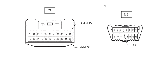
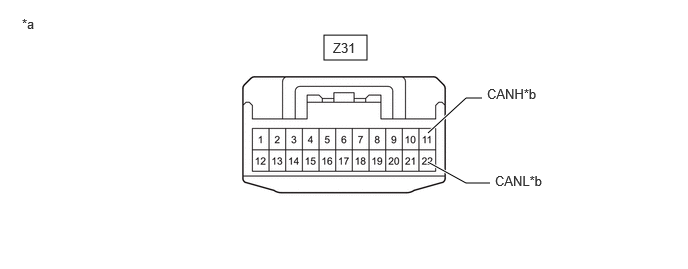
a.

Disconnect the Z31 No. 12 CAN junction connector.


b.

Measure the resistance according to the value(s) in the table below.

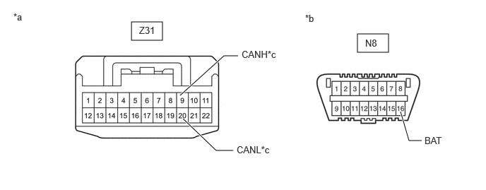
C491476C01
1.938,0.323 2.396,0.594 0.458,0.271 5.271,0.5 5.729,0.771 0.458,0.271 3.052,1.406 3.302,1.01 3.302,1.01 3.49,1.01 true 3.042,1.74 3.24,2.073 3.24,2.073 3.365,2.073 true 5.354,1.344 5.531,1.969 5.531,1.969 5.719,1.969 true 2.052,0.365 2.51,0.563 0.458,0.198 10 false Z31 5.385,0.552 5.844,0.75 0.458,0.198 10 false N8 3.521,0.927 4.146,1.115 0.625,0.188 10 false CANH*c 3.417,1.969 4.042,2.156 0.625,0.188 10 false CANL*c 0.198,0.167 0.469,0.354 0.271,0.188 10 false *a 4.5,0.188 4.771,0.375 0.271,0.188 10 false *b 5.771,1.896 6.396,2.083 0.625,0.188 10 false CG
*a Front view of wire harness connector
(to No. 12 CAN Junction Connector)
*b Front view of DLC3
*c to No. 9 CAN Junction Connector - -


Standard Resistance:
Tester Connection Condition Specified Condition Connect to
Z31-11 (CANH) - N8-4 (CG) Cable disconnected from negative (-) battery terminal 200 Ω or higher No. 9 CAN junction connector
Z31-22 (CANL) - N8-4 (CG)


Result:
Proceed to
OK
NG


OK

17.CHECK VEHICLE TYPE

NG

REPAIR OR REPLACE CAN BUS WIRE OR CONNECTOR (NO. 12 CAN JUNCTION CONNECTOR - NO. 9 CAN JUNCTION CONNECTOR)

17.CHECK VEHICLE TYPE
a.

Check for vehicle type.


Result:
Result Proceed to
w/ Blind Spot Monitor System A
w/o Blind Spot Monitor System B


A

18.CHECK FOR SHORT TO GND IN CAN BUS WIRE (NO. 12 CAN JUNCTION CONNECTOR - BLIND SPOT MONITOR SENSOR LH)

B

19.CHECK VEHICLE TYPE
18.CHECK FOR SHORT TO GND IN CAN BUS WIRE (NO. 12 CAN JUNCTION CONNECTOR - BLIND SPOT MONITOR SENSOR LH)
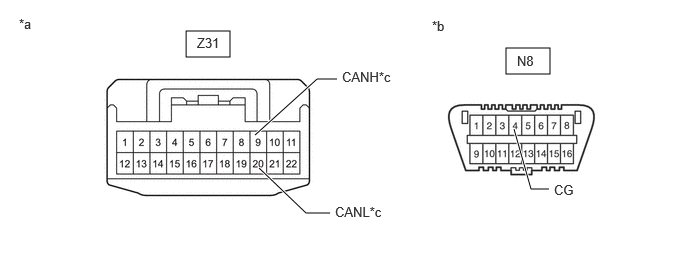
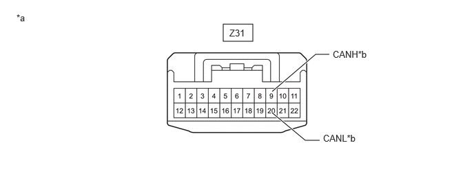
a.

Measure the resistance according to the value(s) in the table below.

C491476C05
1.938,0.323 2.396,0.594 0.458,0.271 5.271,0.5 5.729,0.771 0.458,0.271 2.656,1.406 3.302,0.823 3.302,0.823 3.51,0.823 true 2.698,1.75 3.188,2.219 3.188,2.219 3.438,2.219 true 5.354,1.344 5.531,1.969 5.531,1.969 5.719,1.969 true 2.052,0.365 2.51,0.563 0.458,0.198 10 false Z31 5.385,0.552 5.844,0.75 0.458,0.198 10 false N8 3.563,0.719 4.188,0.906 0.625,0.188 10 false CANH*c 3.49,2.125 4.115,2.313 0.625,0.188 10 false CANL*c 0.198,0.167 0.469,0.354 0.271,0.188 10 false *a 4.5,0.188 4.771,0.375 0.271,0.188 10 false *b 5.771,1.896 6.396,2.083 0.625,0.188 10 false CG
*a Front view of wire harness connector
(to No. 12 CAN Junction Connector)
*b Front view of DLC3
*c to Blind Spot Monitor Sensor LH - -


Standard Resistance:
Tester Connection Condition Specified Condition Connect to
Z31-9 (CANH) - N8-4 (CG) Cable disconnected from negative (-) battery terminal 200 Ω or higher Blind spot monitor sensor LH
Z31-20 (CANL) - N8-4 (CG)


Result:
Proceed to
OK
NG


OK

19.CHECK VEHICLE TYPE

NG

26.CHECK FOR SHORT TO GND IN CAN BUS WIRE (BLIND SPOT MONITOR SENSOR LH - NO. 12 CAN JUNCTION CONNECTOR)
19.CHECK VEHICLE TYPE
a.

Check for vehicle type.


Result:
Result Proceed to
w/ Parking Assist Monitor System A
w/o Parking Assist Monitor System B


A

20.CHECK FOR SHORT TO GND IN CAN BUS WIRE (NO. 12 CAN JUNCTION CONNECTOR - TELEVISION CAMERA ASSEMBLY)

B

21.CHECK FOR SHORT TO GND IN CAN BUS WIRE (NO. 12 CAN JUNCTION CONNECTOR - NO. 3 CAN JUNCTION TERMINAL)
20.CHECK FOR SHORT TO GND IN CAN BUS WIRE (NO. 12 CAN JUNCTION CONNECTOR - TELEVISION CAMERA ASSEMBLY)
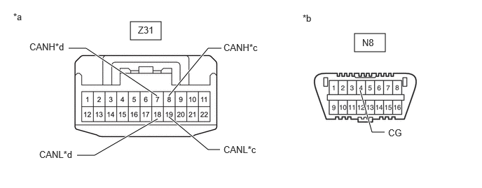
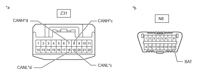
a.

Measure the resistance according to the value(s) in the table below.

C491476C06
1.938,0.323 2.396,0.594 0.458,0.271 5.271,0.5 5.729,0.771 0.458,0.271 2.51,1.427 3.094,0.719 3.094,0.719 3.292,0.719 true 2.51,1.74 3.094,2.229 3.094,2.229 3.271,2.229 true 5.354,1.344 5.531,1.969 5.531,1.969 5.719,1.969 true 2.333,1.427 1.281,0.719 1.281,0.719 1.021,0.719 true 2.344,1.771 1.406,2.313 1.406,2.313 1.146,2.313 true 2.052,0.365 2.51,0.563 0.458,0.198 10 false Z31 5.385,0.552 5.844,0.75 0.458,0.198 10 false N8 3.323,0.625 3.948,0.813 0.625,0.188 10 false CANH*c 3.323,2.146 3.948,2.333 0.625,0.188 10 false CANL*c 0.198,0.167 0.469,0.354 0.271,0.188 10 false *a 4.5,0.188 4.771,0.375 0.271,0.188 10 false *b 5.771,1.896 6.396,2.083 0.625,0.188 10 false CG 0.438,0.615 1.063,0.802 0.625,0.188 10 false CANH*d 0.583,2.219 1.208,2.406 0.625,0.188 10 false CANL*d
*a Front view of wire harness connector
(to No. 12 CAN Junction Connector)
*b Front view of DLC3
*c to Television Camera Assembly (except Double Swing Out Type) *d to Television Camera Assembly (for Double Swing Out Type)


Standard Resistance:
Tester Connection Condition Specified Condition Connect to

*1: except Double Swing Out Type

*2: for Double Swing Out Type

Z31-8 (CANH) - N8-4 (CG)*1 Cable disconnected from negative (-) battery terminal 200 Ω or higher Television camera assembly
Z31-19 (CANL) - N8-4 (CG)*1
Z31-7 (CANH) - N8-4 (CG)*2 Cable disconnected from negative (-) battery terminal 200 Ω or higher
Z31-18 (CANL) - N8-4 (CG)*2


Result:
Proceed to
OK
NG


OK

21.CHECK FOR SHORT TO GND IN CAN BUS WIRE (NO. 12 CAN JUNCTION CONNECTOR - NO. 3 CAN JUNCTION TERMINAL)

NG

27.CHECK FOR SHORT TO GND IN CAN BUS WIRE (TELEVISION CAMERA ASSEMBLY - NO. 12 CAN JUNCTION CONNECTOR)
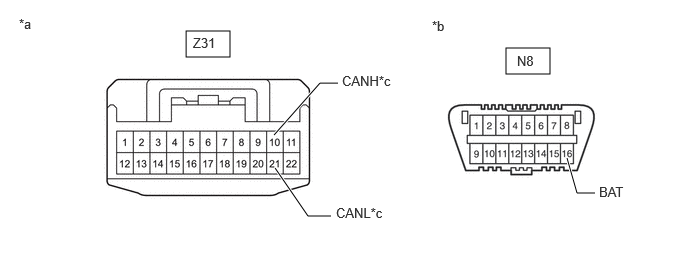
21.CHECK FOR SHORT TO GND IN CAN BUS WIRE (NO. 12 CAN JUNCTION CONNECTOR - NO. 3 CAN JUNCTION TERMINAL)
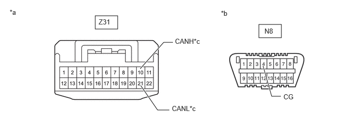
a.

Measure the resistance according to the value(s) in the table below.

C491476C07
1.938,0.323 2.396,0.594 0.458,0.271 5.271,0.5 5.729,0.771 0.458,0.271 2.854,1.406 3.333,0.865 3.333,0.865 3.521,0.865 true 2.865,1.75 3.208,2.25 3.208,2.25 3.448,2.25 true 5.354,1.344 5.531,1.969 5.531,1.969 5.719,1.969 true 2.01,0.365 2.469,0.563 0.458,0.198 10 false Z31 5.385,0.552 5.844,0.75 0.458,0.198 10 false N8 3.563,0.76 4.188,0.948 0.625,0.188 10 false CANH*c 3.5,2.135 4.125,2.323 0.625,0.188 10 false CANL*c 0.198,0.167 0.469,0.354 0.271,0.188 10 false *a 4.5,0.188 4.771,0.375 0.271,0.188 10 false *b 5.771,1.896 6.396,2.083 0.625,0.188 10 false CG
*a Front view of wire harness connector
(to No. 12 CAN Junction Connector)
*b Front view of DLC3
*c to No. 3 CAN Junction Terminal - -


Standard Resistance:
Tester Connection Condition Specified Condition Connect to
Z31-10 (CANH) - N8-4 (CG) Cable disconnected from negative (-) battery terminal 200 Ω or higher No. 3 CAN junction terminal
Z31-21 (CANL) - N8-4 (CG)


Result:
Proceed to
OK
NG


OK

REPLACE NO. 12 CAN JUNCTION CONNECTOR

NG

REPAIR OR REPLACE CAN BUS WIRE OR CONNECTOR (NO. 12 CAN JUNCTION CONNECTOR - NO. 3 CAN JUNCTION TERMINAL)

22.CHECK FOR SHORT TO GND IN CAN BUS WIRE (PARKING ASSIST ECU - NO. 9 CAN JUNCTION CONNECTOR)
a.

Disconnect the N151 parking assist ECU connector.
C324441
1.875,0.094 2.302,0.323 0.427,0.229 5.073,0.104 5.5,0.333 0.427,0.229 3.115,0.813 3.333,0.5 3.333,0.5 3.5,0.5 true 3.115,0.917 3.333,1.25 3.333,1.25 3.5,1.25 true 5.208,0.802 5.594,1.51 5.594,1.51 5.76,1.51 true 1.917,0.135 2.531,0.333 0.615,0.198 10 false N151 5.198,0.135 5.813,0.333 0.615,0.198 10 false N8 0.083,0.073 0.698,0.271 0.615,0.198 10 false *a 4.167,0.125 4.781,0.323 0.615,0.198 10 false *b 3.552,0.427 4.167,0.625 0.615,0.198 10 false CANL 3.552,1.167 4.167,1.365 0.615,0.198 10 false CANH 5.823,1.448 6.438,1.646 0.615,0.198 10 false CG
*a Front view of wire harness connector
(to Parking Assist ECU)
*b Front view of DLC3


b.

Measure the resistance according to the value(s) in the table below.

Standard Resistance:
Tester Connection Condition Specified Condition
N151-40 (CANH) - N8-4 (CG) Cable disconnected from negative (-) battery terminal 200 Ω or higher
N151-18 (CANL) - N8-4 (CG)


c.

Reconnect the N151 parking assist ECU connector.


Result:
Proceed to
OK
NG


OK

NG

REPAIR OR REPLACE CAN BUS WIRE OR CONNECTOR (PARKING ASSIST ECU - NO. 9 CAN JUNCTION CONNECTOR)

23.CHECK FOR SHORT TO GND IN CAN BUS WIRE (MILLIMETER WAVE RADAR SENSOR ASSEMBLY - NO. 9 CAN JUNCTION CONNECTOR)
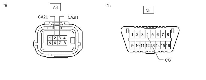
a.

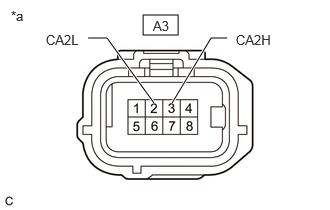
Disconnect the A3 millimeter wave radar sensor assembly connector.
C350887C48
4.99,0.208 5.354,0.479 0.365,0.271 1.74,0.115 2.104,0.385 0.365,0.271 2.073,1.26 2.073,0.573 2.073,0.573 2.229,0.573 true 1.906,1.26 1.906,0.573 1.906,0.573 1.729,0.573 true 5.688,2.094 5.531,2.094 5.531,2.094 5.125,1.281 true 0.115,0.094 0.427,0.292 0.313,0.198 10 false *a 3.719,0.115 4.031,0.313 0.313,0.198 10 false *b 1.323,0.51 1.802,0.719 0.479,0.208 10 false CA2L 2.354,0.521 2.833,0.729 0.479,0.208 10 false CA2H 5.74,2.021 6.219,2.229 0.479,0.208 10 false CG 5.063,0.281 5.385,0.479 0.323,0.198 10 false N8 1.844,0.177 2.167,0.375 0.323,0.198 10 false A3
*a Front view of wire harness connector
(to Millimeter Wave Radar Sensor Assembly)
*b Front view of DLC3


b.

Measure the resistance according to the value(s) in the table below.

Standard Resistance:
Tester Connection Condition Specified Condition
A3-3 (CA2H) - N8-4 (CG) Cable disconnected from negative (-) battery terminal 200 Ω or higher
A3-2 (CA2L) - N8-4 (CG)


c.

Reconnect the A3 millimeter wave radar sensor assembly connector.


Result:
Proceed to
OK
NG


OK

NG

REPAIR OR REPLACE CAN BUS WIRE OR CONNECTOR (MILLIMETER WAVE RADAR SENSOR ASSEMBLY - NO. 9 CAN JUNCTION CONNECTOR)

24.CHECK FOR SHORT TO GND IN CAN BUS WIRE (FORWARD RECOGNITION CAMERA - NO. 9 CAN JUNCTION CONNECTOR)
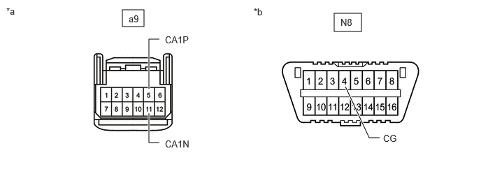
a.

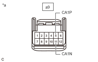
Disconnect the a9 forward recognition camera connector.
C350886C45
1.823,0.146 2.146,0.396 0.323,0.25 4.979,0.198 5.385,0.469 0.406,0.271 2.219,1.688 2.219,2.125 2.219,2.125 2.375,2.125 true 2.219,1.323 2.219,0.583 2.219,0.583 2.375,0.583 true 5.146,1.292 5.5,2.052 5.5,2.052 5.656,2.052 true 0.094,0.083 0.406,0.281 0.313,0.198 10 false *a 3.781,0.094 4.094,0.292 0.313,0.198 10 false *b 1.917,0.198 2.229,0.396 0.313,0.198 10 false a9 2.458,0.51 2.927,0.729 0.469,0.219 10 false CA1P 2.458,2.063 2.927,2.281 0.469,0.219 10 false CA1N 5.073,0.25 5.385,0.448 0.313,0.198 10 false N8 5.708,1.979 6.177,2.198 0.469,0.219 10 false CG
*a Front view of wire harness connector
(to Forward Recognition Camera)
*b Front view of DLC3


b.

Measure the resistance according to the value(s) in the table below.

Standard Resistance:
Tester Connection Condition Specified Condition
a9-5 (CA1P) - N8-4 (CG) Cable disconnected from negative (-) battery terminal 200 Ω or higher
a9-11 (CA1N) - N8-4 (CG)


c.

Reconnect the a9 forward recognition camera connector.


Result:
Proceed to
OK
NG


OK

NG

REPAIR OR REPLACE CAN BUS WIRE OR CONNECTOR (FORWARD RECOGNITION CAMERA - NO. 9 CAN JUNCTION CONNECTOR)

25.CHECK FOR SHORT TO GND IN CAN BUS WIRE (CLEARANCE WARNING ECU ASSEMBLY - NO. 9 CAN JUNCTION CONNECTOR)
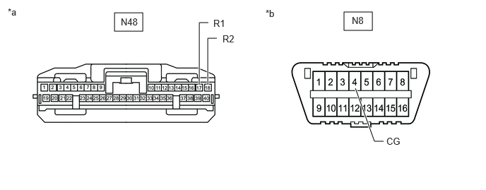
a.

Disconnect the N48 clearance warning ECU assembly connector.
C350879C30
1.688,0.188 2.104,0.458 0.417,0.271 5.073,0.177 5.49,0.448 0.417,0.271 2.938,1.25 2.938,0.333 2.938,0.333 3.073,0.333 true 3.063,1.25 3.063,0.563 3.063,0.563 3.198,0.563 true 5.656,2.083 5.521,2.083 5.521,2.083 5.24,1.302 true 0.115,0.094 0.427,0.292 0.313,0.198 10 false *a 3.917,0.115 4.229,0.313 0.313,0.198 10 false *b 3.146,0.26 3.458,0.458 0.313,0.198 10 false R1 3.281,0.49 3.594,0.688 0.313,0.198 10 false R2 1.781,0.24 2.167,0.51 0.385,0.271 10 false N48 5.698,2 6.219,2.208 0.521,0.208 10 false CG 5.188,0.219 5.573,0.49 0.385,0.271 10 false N8
*a Front view of wire harness connector
(to Clearance Warning ECU Assembly)
*b Front view of DLC3


b.

Measure the resistance according to the value(s) in the table below.

Standard Resistance:
Tester Connection Condition Specified Condition
N48-17 (R1) - N8-4 (CG) Cable disconnected from negative (-) battery terminal 200 Ω or higher
N48-18 (R2) - N8-4 (CG)


c.

Reconnect the N48 clearance warning ECU assembly connector.


Result:
Proceed to
OK
NG


OK

NG

REPAIR OR REPLACE CAN BUS WIRE OR CONNECTOR (CLEARANCE WARNING ECU ASSEMBLY - NO. 9 CAN JUNCTION CONNECTOR)

26.CHECK FOR SHORT TO GND IN CAN BUS WIRE (BLIND SPOT MONITOR SENSOR LH - NO. 12 CAN JUNCTION CONNECTOR)
a.

Disconnect the e2 blind spot monitor sensor LH connector.
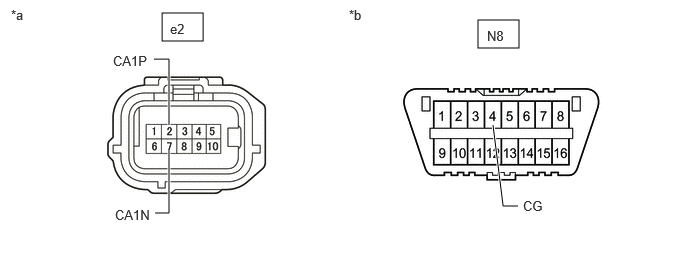
C350884C44
1.688,0.135 2.115,0.427 0.427,0.292 4.979,0.208 5.406,0.5 0.427,0.292 1.76,1.302 1.76,0.615 1.76,0.615 1.604,0.615 true 1.615,2.219 1.76,2.219 1.76,2.219 1.76,1.563 true 5.396,2.146 5.24,2.146 5.24,2.146 5.135,1.302 true 0.115,0.073 0.427,0.271 0.313,0.198 10 false *a 3.635,0.073 3.948,0.271 0.313,0.198 10 false *b 1.771,0.219 2.094,0.417 0.323,0.198 10 false e2 5.073,0.292 5.396,0.49 0.323,0.198 10 false N8 1.198,2.156 1.688,2.406 0.49,0.25 10 false CA1N 1.177,0.552 1.667,0.802 0.49,0.25 10 false CA1P 5.448,2.063 5.938,2.313 0.49,0.25 10 false CG
*a Front view of wire harness connector
(to Blind Spot Monitor Sensor LH)
*b Front view of DLC3


b.

Measure the resistance according to the value(s) in the table below.

Standard Resistance:
Tester Connection Condition Specified Condition
e2-2 (CA1P) - N8-4 (CG) Cable disconnected from negative (-) battery terminal 200 Ω or higher
e2-7 (CA1N) - N8-4 (CG)


Result:
Proceed to
OK
NG


OK

NG

REPAIR OR REPLACE CAN BUS WIRE OR CONNECTOR (BLIND SPOT MONITOR SENSOR LH - NO. 12 CAN JUNCTION CONNECTOR)

27.CHECK FOR SHORT TO GND IN CAN BUS WIRE (TELEVISION CAMERA ASSEMBLY - NO. 12 CAN JUNCTION CONNECTOR)

*1: except Double Swing Out Type

*2: for Double Swing Out Type


a.

Disconnect the i7*1, k9*2 television camera assembly connector.
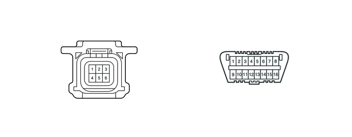
C387471
1.854,0.26 2.208,0.49 0.354,0.229 4.917,0.479 5.354,0.708 0.438,0.229 1.854,0.531 2.208,0.76 0.354,0.229 1.302,0.698 1.469,0.698 1.469,0.698 1.865,1.385 true 1.375,2.229 1.542,2.229 1.542,2.229 1.885,1.604 true 4.594,1.885 4.76,1.885 4.76,1.885 5.104,1.26 true 0.813,0.156 1.125,0.354 0.313,0.198 10 false *a 4.021,0.156 4.333,0.354 0.313,0.198 10 false *b 1.979,0.281 2.229,0.448 0.25,0.167 10 false i7 4.979,0.51 5.354,0.698 0.375,0.188 10 false N8 0.875,0.625 1.375,0.813 0.5,0.188 10 false CANL 0.938,2.156 1.427,2.365 0.49,0.208 10 false CANH 4.365,1.802 4.802,1.99 0.438,0.188 10 false CG 2.25,0.292 2.5,0.458 0.25,0.167 10 false *A 1.958,0.563 2.208,0.729 0.25,0.167 10 false k9 2.25,0.542 2.5,0.708 0.25,0.167 10 false *B
*A except Double Swing Out Type *B for Double Swing Out Type
*a Front view of wire harness connector
(to Television Camera Assembly)
*b Front view of DLC3


b.

Measure the resistance according to the value(s) in the table below.

Standard Resistance:
Tester Connection Condition Specified Condition

*1: except Double Swing Out Type

*2: for Double Swing Out Type

i7-4 (CANH) - N8-4 (CG)*1 Cable disconnected from negative (-) battery terminal 200 Ω or higher
i7-1 (CANL) - N8-4 (CG)*1
k9-4 (CANH) - N8-4 (CG)*2 Cable disconnected from negative (-) battery terminal 200 Ω or higher
k9-1 (CANL) - N8-4 (CG)*2


Result:
Proceed to
OK
NG


OK

NG

REPAIR OR REPLACE CAN BUS WIRE OR CONNECTOR (TELEVISION CAMERA ASSEMBLY - NO. 12 CAN JUNCTION CONNECTOR)

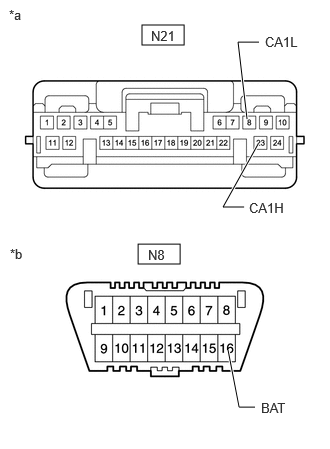
28.CHECK FOR SHORT TO B+ IN CAN BUS WIRE (CENTRAL GATEWAY ECU [NETWORK GATEWAY ECU] - NO. 9 CAN JUNCTION CONNECTOR)
a.
C414215C10
1.479,0.26 1.917,0.469 0.438,0.208 1.438,2.542 1.875,2.75 0.438,0.208 2.698,0.438 2.479,0.438 2.479,0.438 2.573,1.24 true 2.656,4.24 2.49,4.24 2.49,4.24 2.375,3.646 true 2.542,2.156 2.323,2.156 2.323,2.156 2.688,1.5 true 1.573,0.292 2.188,0.49 0.615,0.198 10 false N21 1.542,2.573 2.156,2.771 0.615,0.198 10 false N8 0.094,0.073 0.708,0.271 0.615,0.198 10 false *a 0.104,2.563 0.719,2.76 0.615,0.198 10 false *b 2.76,0.354 3.292,0.563 0.531,0.208 10 false CA1L 2.719,4.167 3.135,4.385 0.417,0.219 10 false BAT 2.594,2.083 3.125,2.292 0.531,0.208 10 false CA1H
*a Front view of wire harness connector
(to Central Gateway ECU [Network Gateway ECU])
*b Front view of DLC3


Disconnect the N21 central gateway ECU (network gateway ECU) connector.


b.

Measure the resistance according to the value(s) in the table below.

Standard Resistance:
Tester Connection Condition Specified Condition
N21-23 (CA1H) - N8-16 (BAT) Cable disconnected from negative (-) battery terminal 6 kΩ or higher
N21-8 (CA1L) - N8-16 (BAT)


c.

Reconnect the N21 central gateway ECU (network gateway ECU) connector.


Result:
Proceed to
OK
NG


OK

NG

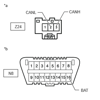
29.CHECK FOR SHORT TO B+ IN CAN BUS WIRE (NO. 3 CAN JUNCTION TERMINAL - NO. 12 CAN JUNCTION CONNECTOR)
a.
C414349C04
0.365,0.781 0.854,1.042 0.49,0.26 0.125,2.385 0.615,2.646 0.49,0.26 2.375,2.688 2.583,3.094 2.583,3.094 2.719,3.094 true 1.938,0.885 2.208,0.406 2.208,0.406 2.344,0.406 true 1.292,0.427 1.448,0.427 1.448,0.427 1.729,0.906 true 0.51,0.833 1.125,1.031 0.615,0.198 10 false Z24 0.292,2.438 0.906,2.635 0.615,0.198 10 false N8 2.781,3.021 3.094,3.219 0.313,0.198 10 false BAT 2.375,0.323 2.99,0.521 0.615,0.198 10 false CANH 0.885,0.344 1.5,0.542 0.615,0.198 10 false CANL 0.135,0.104 0.448,0.302 0.313,0.198 10 false *a 0.135,1.594 0.448,1.792 0.313,0.198 10 false *b
*a Front view of wire harness connector
(to No. 3 CAN Junction Terminal)
*b Front view of DLC3


Disconnect the Z24 No. 3 CAN junction terminal connector.


b.

Measure the resistance according to the value(s) in the table below.

Standard Resistance:
Tester Connection Condition Specified Condition
Z24-3 (CANH) - N8-16 (BAT) Cable disconnected from negative (-) battery terminal 6 kΩ or higher
Z24-2 (CANL) - N8-16 (BAT)


c.

Reconnect the Z24 No. 3 CAN junction terminal connector.


Result:
Proceed to
OK
NG


OK

REPLACE NO. 3 CAN JUNCTION TERMINAL

NG

30.CHECK FOR SHORT TO B+ IN CAN BUS WIRE (NO. 9 CAN JUNCTION CONNECTOR - CENTRAL GATEWAY ECU [NETWORK GATEWAY ECU])
HINT:
·

Distinguish between the connectors connected to the No. 9 CAN junction connector by checking the color of the communication wire.

·

Before disconnecting the connectors, make a note of where it is connected.

·

Reconnect the connector to its original position.


a.

Disconnect the N222 No. 9 CAN junction connector.
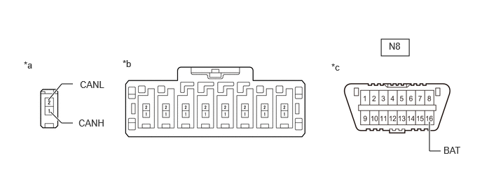
C421483C44
5.667,0.583 6.083,0.833 0.417,0.25 0.75,1.667 0.917,1.833 0.917,1.833 1.083,1.833 true 0.719,1.49 0.917,1.25 0.917,1.25 1.083,1.25 true 6.385,1.813 6.385,2.25 6.385,2.25 6.552,2.25 true 1.823,0.865 2.135,1.063 0.313,0.198 10 false *b 0.354,0.885 0.667,1.083 0.313,0.198 10 false *a 5.781,0.604 6.385,0.813 0.604,0.208 10 false N8 1.188,1.177 1.698,1.385 0.51,0.208 10 false CANL 4.927,0.917 5.24,1.115 0.313,0.198 10 false *c 1.167,1.75 1.677,1.958 0.51,0.208 10 false CANH 6.594,2.156 6.948,2.323 0.354,0.167 10 false BAT
*a Vehicle wire harness connector connected to CAN junction connector *b Rear view of wire harness connector
(to No. 9 CAN Junction Connector)
*c Front view of DLC3 - -


b.

Measure the resistance according to the value(s) in the table below.
Standard Resistance:
Tester Connection Wiring Color Condition Specified Condition Connect to
N222-1 (CANH) - N8-16 (BAT) G - W-B Cable disconnected from negative (-) battery terminal 6 kΩ or higher Central gateway ECU (network gateway ECU)
N222-2 (CANL) - N8-16 (BAT) W - W-B


Result:
Proceed to
OK
NG


OK

31.CHECK VEHICLE TYPE

NG

REPAIR OR REPLACE CAN BUS WIRE OR CONNECTOR (NO. 9 CAN JUNCTION CONNECTOR - CENTRAL GATEWAY ECU [NETWORK GATEWAY ECU])

31.CHECK VEHICLE TYPE
a.

Check for vehicle type.


Result:
Result Proceed to
w/ Panoramic View Monitor System A
w/o Panoramic View Monitor System B


A

32.CHECK FOR SHORT TO B+ IN CAN BUS WIRE (NO. 9 CAN JUNCTION CONNECTOR - PARKING ASSIST ECU)

B

33.CHECK VEHICLE TYPE
32.CHECK FOR SHORT TO B+ IN CAN BUS WIRE (NO. 9 CAN JUNCTION CONNECTOR - PARKING ASSIST ECU)
HINT:
·

Distinguish between the connectors connected to the No. 9 CAN junction connector by checking the color of the communication wire.

·

Before disconnecting the connectors, make a note of where it is connected.

·

Reconnect the connector to its original position.


a.

Disconnect the N224 No. 9 CAN junction connector.

C421483C44
5.667,0.583 6.083,0.833 0.417,0.25 0.75,1.667 0.917,1.833 0.917,1.833 1.083,1.833 true 0.719,1.49 0.917,1.25 0.917,1.25 1.083,1.25 true 6.385,1.813 6.385,2.25 6.385,2.25 6.552,2.25 true 1.823,0.865 2.135,1.063 0.313,0.198 10 false *b 0.354,0.885 0.667,1.083 0.313,0.198 10 false *a 5.781,0.604 6.385,0.813 0.604,0.208 10 false N8 1.188,1.177 1.698,1.385 0.51,0.208 10 false CANL 4.927,0.917 5.24,1.115 0.313,0.198 10 false *c 1.167,1.75 1.677,1.958 0.51,0.208 10 false CANH 6.594,2.156 6.948,2.323 0.354,0.167 10 false BAT
*a Vehicle wire harness connector connected to CAN junction connector *b Rear view of wire harness connector
(to No. 9 CAN Junction Connector)
*c Front view of DLC3 - -


b.

Measure the resistance according to the value(s) in the table below.
Standard Resistance:
Tester Connection Wiring Color Condition Specified Condition Connect to
N224-1 (CANH) - N8-16 (BAT) P - W-B Cable disconnected from negative (-) battery terminal 6 kΩ or higher Parking assist ECU
N224-2 (CANL) - N8-16 (BAT) W - W-B


Result:
Proceed to
OK
NG


OK

33.CHECK VEHICLE TYPE

NG

45.CHECK FOR SHORT TO B+ IN CAN BUS WIRE (PARKING ASSIST ECU - NO. 9 CAN JUNCTION CONNECTOR)
33.CHECK VEHICLE TYPE
a.

Check for vehicle type.


Result:
Result Proceed to
w/ Pre-collision System A
w/o Pre-collision System B


A

34.CHECK FOR SHORT TO B+ IN CAN BUS WIRE (NO. 9 CAN JUNCTION CONNECTOR - MILLIMETER WAVE RADAR SENSOR ASSEMBLY)

B

36.CHECK VEHICLE TYPE
34.CHECK FOR SHORT TO B+ IN CAN BUS WIRE (NO. 9 CAN JUNCTION CONNECTOR - MILLIMETER WAVE RADAR SENSOR ASSEMBLY)
HINT:
·

Distinguish between the connectors connected to the No. 9 CAN junction connector by checking the color of the communication wire.

·

Before disconnecting the connectors, make a note of where it is connected.

·

Reconnect the connector to its original position.


a.

Disconnect the N226 No. 9 CAN junction connector.

C421483C44
5.667,0.583 6.083,0.833 0.417,0.25 0.75,1.667 0.917,1.833 0.917,1.833 1.083,1.833 true 0.719,1.49 0.917,1.25 0.917,1.25 1.083,1.25 true 6.385,1.813 6.385,2.25 6.385,2.25 6.552,2.25 true 1.823,0.865 2.135,1.063 0.313,0.198 10 false *b 0.354,0.885 0.667,1.083 0.313,0.198 10 false *a 5.781,0.604 6.385,0.813 0.604,0.208 10 false N8 1.188,1.177 1.698,1.385 0.51,0.208 10 false CANL 4.927,0.917 5.24,1.115 0.313,0.198 10 false *c 1.167,1.75 1.677,1.958 0.51,0.208 10 false CANH 6.594,2.156 6.948,2.323 0.354,0.167 10 false BAT
*a Vehicle wire harness connector connected to CAN junction connector *b Rear view of wire harness connector
(to No. 9 CAN Junction Connector)
*c Front view of DLC3 - -


b.

Measure the resistance according to the value(s) in the table below.
Standard Resistance:
Tester Connection Wiring Color Condition Specified Condition Connect to
N226-1 (CANH) - N8-16 (BAT) R - W-B Cable disconnected from negative (-) battery terminal 6 kΩ or higher Millimeter wave radar sensor assembly
N226-2 (CANL) - N8-16 (BAT) W - W-B


Result:
Proceed to
OK
NG


OK

35.CHECK FOR SHORT TO B+ IN CAN BUS WIRE (NO. 9 CAN JUNCTION CONNECTOR - FORWARD RECOGNITION CAMERA)

NG

46.CHECK FOR SHORT TO B+ IN CAN BUS WIRE (MILLIMETER WAVE RADAR SENSOR ASSEMBLY - NO. 9 CAN JUNCTION CONNECTOR)
35.CHECK FOR SHORT TO B+ IN CAN BUS WIRE (NO. 9 CAN JUNCTION CONNECTOR - FORWARD RECOGNITION CAMERA)
HINT:
·

Distinguish between the connectors connected to the No. 9 CAN junction connector by checking the color of the communication wire.

·

Before disconnecting the connectors, make a note of where it is connected.

·

Reconnect the connector to its original position.


a.

Disconnect the N227 No. 9 CAN junction connector.

C421483C44
5.667,0.583 6.083,0.833 0.417,0.25 0.75,1.667 0.917,1.833 0.917,1.833 1.083,1.833 true 0.719,1.49 0.917,1.25 0.917,1.25 1.083,1.25 true 6.385,1.813 6.385,2.25 6.385,2.25 6.552,2.25 true 1.823,0.865 2.135,1.063 0.313,0.198 10 false *b 0.354,0.885 0.667,1.083 0.313,0.198 10 false *a 5.781,0.604 6.385,0.813 0.604,0.208 10 false N8 1.188,1.177 1.698,1.385 0.51,0.208 10 false CANL 4.927,0.917 5.24,1.115 0.313,0.198 10 false *c 1.167,1.75 1.677,1.958 0.51,0.208 10 false CANH 6.594,2.156 6.948,2.323 0.354,0.167 10 false BAT
*a Vehicle wire harness connector connected to CAN junction connector *b Rear view of wire harness connector
(to No. 9 CAN Junction Connector)
*c Front view of DLC3 - -


b.

Measure the resistance according to the value(s) in the table below.
Standard Resistance:
Tester Connection Wiring Color Condition Specified Condition Connect to
N227-1 (CANH) - N8-16 (BAT) V - W-B Cable disconnected from negative (-) battery terminal 6 kΩ or higher Forward recognition camera
N227-2 (CANL) - N8-16 (BAT) W - W-B


Result:
Proceed to
OK
NG


OK

36.CHECK VEHICLE TYPE

NG

47.CHECK FOR SHORT TO B+ IN CAN BUS WIRE (FORWARD RECOGNITION CAMERA - NO. 9 CAN JUNCTION CONNECTOR)
36.CHECK VEHICLE TYPE
a.

Check for vehicle type.


Result:
Result Proceed to
w/ TOYOTA Parking Assist-sensor System A
w/o TOYOTA Parking Assist-sensor System B


A

37.CHECK FOR SHORT TO B+ IN CAN BUS WIRE (NO. 9 CAN JUNCTION CONNECTOR - CLEARANCE WARNING ECU ASSEMBLY)

B

38.CHECK FOR SHORT TO B+ IN CAN BUS WIRE (NO. 9 CAN JUNCTION CONNECTOR - NO. 12 CAN JUNCTION CONNECTOR)
37.CHECK FOR SHORT TO B+ IN CAN BUS WIRE (NO. 9 CAN JUNCTION CONNECTOR - CLEARANCE WARNING ECU ASSEMBLY)
HINT:
·

Distinguish between the connectors connected to the No. 9 CAN junction connector by checking the color of the communication wire.

·

Before disconnecting the connectors, make a note of where it is connected.

·

Reconnect the connector to its original position.


a.

Disconnect the N223 No. 9 CAN junction connector.

C421483C44
5.667,0.583 6.083,0.833 0.417,0.25 0.75,1.667 0.917,1.833 0.917,1.833 1.083,1.833 true 0.719,1.49 0.917,1.25 0.917,1.25 1.083,1.25 true 6.385,1.813 6.385,2.25 6.385,2.25 6.552,2.25 true 1.823,0.865 2.135,1.063 0.313,0.198 10 false *b 0.354,0.885 0.667,1.083 0.313,0.198 10 false *a 5.781,0.604 6.385,0.813 0.604,0.208 10 false N8 1.188,1.177 1.698,1.385 0.51,0.208 10 false CANL 4.927,0.917 5.24,1.115 0.313,0.198 10 false *c 1.167,1.75 1.677,1.958 0.51,0.208 10 false CANH 6.594,2.156 6.948,2.323 0.354,0.167 10 false BAT
*a Vehicle wire harness connector connected to CAN junction connector *b Rear view of wire harness connector
(to No. 9 CAN Junction Connector)
*c Front view of DLC3 - -


b.

Measure the resistance according to the value(s) in the table below.

Standard Resistance:
Tester Connection Wiring Color Condition Specified Condition Connect to
N223-1 (CANH) - N8-16 (BAT) L - W-B Cable disconnected from negative (-) battery terminal 6 kΩ or higher Clearance warning ECU assembly
N223-2 - N8-16 (BAT) W - W-B


Result:
Proceed to
OK
NG


OK

38.CHECK FOR SHORT TO B+ IN CAN BUS WIRE (NO. 9 CAN JUNCTION CONNECTOR - NO. 12 CAN JUNCTION CONNECTOR)

NG

48.CHECK FOR SHORT TO B+ IN CAN BUS WIRE (CLEARANCE WARNING ECU ASSEMBLY - NO. 9 CAN JUNCTION CONNECTOR)
38.CHECK FOR SHORT TO B+ IN CAN BUS WIRE (NO. 9 CAN JUNCTION CONNECTOR - NO. 12 CAN JUNCTION CONNECTOR)
HINT:
·

Distinguish between the connectors connected to the No. 9 CAN junction connector by checking the color of the communication wire.

·

Before disconnecting the connectors, make a note of where it is connected.

·

Reconnect the connector to its original position.


a.

Disconnect the N225 No. 9 CAN junction connector.

C421483C44
5.667,0.583 6.083,0.833 0.417,0.25 0.75,1.667 0.917,1.833 0.917,1.833 1.083,1.833 true 0.719,1.49 0.917,1.25 0.917,1.25 1.083,1.25 true 6.385,1.813 6.385,2.25 6.385,2.25 6.552,2.25 true 1.823,0.865 2.135,1.063 0.313,0.198 10 false *b 0.354,0.885 0.667,1.083 0.313,0.198 10 false *a 5.781,0.604 6.385,0.813 0.604,0.208 10 false N8 1.188,1.177 1.698,1.385 0.51,0.208 10 false CANL 4.927,0.917 5.24,1.115 0.313,0.198 10 false *c 1.167,1.75 1.677,1.958 0.51,0.208 10 false CANH 6.594,2.156 6.948,2.323 0.354,0.167 10 false BAT
*a Vehicle wire harness connector connected to CAN junction connector *b Rear view of wire harness connector
(to No. 9 CAN Junction Connector)
*c Front view of DLC3 - -


b.

Measure the resistance according to the value(s) in the table below.

Standard Resistance:
Tester Connection Wiring Color Condition Specified Condition Connect to
N225-1 (CANH) - N8-16 (BAT) P - W-B Cable disconnected from negative (-) battery terminal 6 kΩ or higher No. 12 CAN junction connector
N225-2 (CANL) - N8-16 (BAT) W - W-B


Result:
Proceed to
OK
NG


OK

REPLACE NO. 9 CAN JUNCTION CONNECTOR

NG

39.CHECK FOR SHORT TO B+ IN CAN BUS WIRE (NO. 12 CAN JUNCTION CONNECTOR - NO. 9 CAN JUNCTION CONNECTOR)
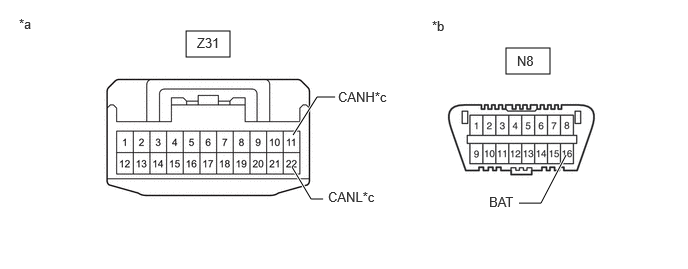
a.

Measure the resistance according to the value(s) in the table below.

C491476C08
1.938,0.323 2.396,0.594 0.458,0.271 5.271,0.5 5.729,0.771 0.458,0.271 3.052,1.406 3.302,1.01 3.302,1.01 3.49,1.01 true 3.042,1.74 3.24,2.073 3.24,2.073 3.365,2.073 true 5.896,1.615 5.635,2.115 5.635,2.115 5.406,2.115 true 2.052,0.365 2.51,0.563 0.458,0.198 10 false Z31 5.385,0.552 5.844,0.75 0.458,0.198 10 false N8 3.521,0.927 4.146,1.115 0.625,0.188 10 false CANH*c 3.417,1.969 4.042,2.156 0.625,0.188 10 false CANL*c 0.198,0.167 0.469,0.354 0.271,0.188 10 false *a 4.5,0.188 4.771,0.375 0.271,0.188 10 false *b 5.094,2.021 5.479,2.229 0.385,0.208 10 false BAT
*a Front view of wire harness connector
(to No. 12 CAN Junction Connector)
*b Front view of DLC3
*c to No. 9 CAN Junction Connector - -


Standard Resistance:
Tester Connection Condition Specified Condition Connect to
Z31-11 (CANH) - N8-16 (BAT) Cable disconnected from negative (-) battery terminal 6 kΩ or higher No. 9 CAN junction connector
Z31-22 (CANL) - N8-16 (BAT)


Result:
Proceed to
OK
NG


OK

40.CHECK VEHICLE TYPE

NG

REPAIR OR REPLACE CAN BUS WIRE OR CONNECTOR (NO. 12 CAN JUNCTION CONNECTOR - NO. 9 CAN JUNCTION CONNECTOR)

40.CHECK VEHICLE TYPE
a.

Check for vehicle type.


Result:
Result Proceed to
w/ Blind Spot Monitor System A
w/o Blind Spot Monitor System B


A

41.CHECK FOR SHORT TO B+ IN CAN BUS WIRE (NO. 12 CAN JUNCTION CONNECTOR - BLIND SPOT MONITOR SENSOR LH)

B

42.CHECK VEHICLE TYPE
41.CHECK FOR SHORT TO B+ IN CAN BUS WIRE (NO. 12 CAN JUNCTION CONNECTOR - BLIND SPOT MONITOR SENSOR LH)
a.

Disconnect the Z31 No. 12 CAN junction connector.


b.

Measure the resistance according to the value(s) in the table below.

C491476C12
1.938,0.323 2.396,0.594 0.458,0.271 5.271,0.5 5.729,0.771 0.458,0.271 2.656,1.406 3.302,0.823 3.302,0.823 3.51,0.823 true 2.698,1.75 3.188,2.219 3.188,2.219 3.438,2.219 true 5.906,1.646 6.031,2.073 6.031,2.073 6.219,2.073 true 2.052,0.365 2.51,0.563 0.458,0.198 10 false Z31 5.385,0.552 5.844,0.75 0.458,0.198 10 false N8 3.563,0.719 4.188,0.906 0.625,0.188 10 false CANH*c 3.49,2.125 4.115,2.313 0.625,0.188 10 false CANL*c 0.198,0.167 0.469,0.354 0.271,0.188 10 false *a 4.5,0.188 4.771,0.375 0.271,0.188 10 false *b 6.26,1.99 6.656,2.156 0.396,0.167 10 false BAT
*a Front view of wire harness connector
(to No. 10 CAN Junction Connector)
*b Front view of DLC3
*c to Blind Spot Monitor Sensor LH - -


Standard Resistance:
Tester Connection Condition Specified Condition Connect to
Z31-9 (CANH) - N8-16 (BAT) Cable disconnected from negative (-) battery terminal 6 kΩ or higher Blind spot monitor sensor LH
Z31-20 (CANL) - N8-16 (BAT)


Result:
Proceed to
OK
NG


OK

42.CHECK VEHICLE TYPE

NG

49.CHECK FOR SHORT TO B+ IN CAN BUS WIRE (BLIND SPOT MONITOR SENSOR LH - NO. 12 CAN JUNCTION CONNECTOR)
42.CHECK VEHICLE TYPE
a.

Check for vehicle type.


Result:
Result Proceed to
w/ Parking Assist Monitor System A
w/o Parking Assist Monitor System B


A

43.CHECK FOR SHORT TO B+ IN CAN BUS WIRE (NO. 12 CAN JUNCTION CONNECTOR - TELEVISION CAMERA ASSEMBLY)

B

44.CHECK FOR SHORT TO B+ IN CAN BUS WIRE (NO. 12 CAN JUNCTION CONNECTOR - NO. 3 CAN JUNCTION TERMINAL)
43.CHECK FOR SHORT TO B+ IN CAN BUS WIRE (NO. 12 CAN JUNCTION CONNECTOR - TELEVISION CAMERA ASSEMBLY)
a.

Measure the resistance according to the value(s) in the table below.

C491476C13
1.938,0.323 2.396,0.594 0.458,0.271 5.271,0.5 5.729,0.771 0.458,0.271 2.51,1.427 3.094,0.719 3.094,0.719 3.292,0.719 true 2.51,1.74 3.094,2.229 3.094,2.229 3.271,2.229 true 5.906,1.646 6.021,2.104 6.021,2.104 6.208,2.104 true 2.333,1.427 1.281,0.719 1.281,0.719 1.021,0.719 true 2.344,1.771 1.406,2.313 1.406,2.313 1.146,2.313 true 2.052,0.365 2.51,0.563 0.458,0.198 10 false Z31 5.385,0.552 5.844,0.75 0.458,0.198 10 false N8 3.323,0.625 3.948,0.813 0.625,0.188 10 false CANH*c 3.323,2.146 3.948,2.333 0.625,0.188 10 false CANL*c 0.198,0.167 0.469,0.354 0.271,0.188 10 false *a 4.5,0.188 4.771,0.375 0.271,0.188 10 false *b 6.271,2.021 6.667,2.208 0.396,0.188 10 false BAT 0.438,0.615 1.063,0.802 0.625,0.188 10 false CANH*d 0.583,2.219 1.208,2.406 0.625,0.188 10 false CANL*d
*a Front view of wire harness connector
(to No. 12 CAN Junction Connector)
*b Front view of DLC3
*c to Television Camera Assembly (except Double Swing Out Type) *d to Television Camera Assembly (for Double Swing Out Type)


Standard Resistance:
Tester Connection Condition Specified Condition Connect to

*1: except Double Swing Out Type

*2: for Double Swing Out Type

Z31-8 (CANH) - N8-16 (BAT)*1 Cable disconnected from negative (-) battery terminal 6 kΩ or higher Television camera assembly
Z31-19 (CANL) - N8-16 (BAT)*1
Z31-7 (CANH) - N8-16 (BAT)*2 Cable disconnected from negative (-) battery terminal 6 kΩ or higher
Z31-18 (CANL) - N8-16 (BAT)*2


Result:
Proceed to
OK
NG


OK

44.CHECK FOR SHORT TO B+ IN CAN BUS WIRE (NO. 12 CAN JUNCTION CONNECTOR - NO. 3 CAN JUNCTION TERMINAL)

NG

50.CHECK FOR SHORT TO B+ IN CAN BUS WIRE (TELEVISION CAMERA ASSEMBLY - NO. 12 CAN JUNCTION CONNECTOR)
44.CHECK FOR SHORT TO B+ IN CAN BUS WIRE (NO. 12 CAN JUNCTION CONNECTOR - NO. 3 CAN JUNCTION TERMINAL)
a.

Measure the resistance according to the value(s) in the table below.

C491476C14
1.938,0.323 2.396,0.594 0.458,0.271 5.271,0.5 5.729,0.771 0.458,0.271 2.854,1.406 3.333,0.865 3.333,0.865 3.521,0.865 true 2.865,1.75 3.208,2.25 3.208,2.25 3.448,2.25 true 5.906,1.646 6.01,2.01 6.01,2.01 6.198,2.01 true 2.01,0.365 2.469,0.563 0.458,0.198 10 false Z31 5.385,0.552 5.844,0.75 0.458,0.198 10 false N8 3.563,0.76 4.188,0.948 0.625,0.188 10 false CANH*c 3.5,2.135 4.125,2.323 0.625,0.188 10 false CANL*c 0.198,0.167 0.469,0.354 0.271,0.188 10 false *a 4.5,0.188 4.771,0.375 0.271,0.188 10 false *b 6.24,1.917 6.625,2.104 0.385,0.188 10 false BAT
*a Front view of wire harness connector
(to No. 12 CAN Junction Connector)
*b Front view of DLC3
*c to No. 3 CAN Junction Terminal - -


Standard Resistance:
Tester Connection Condition Specified Condition Connect to
Z31-10 (CANH) - N8-16 (BAT) Cable disconnected from negative (-) battery terminal 6 kΩ or higher No. 3 CAN junction terminal
Z31-21 (CANL) - N8-16 (BAT)


Result:
Proceed to
OK
NG


OK

REPLACE NO. 12 CAN JUNCTION CONNECTOR

NG

REPAIR OR REPLACE CAN BUS WIRE OR CONNECTOR (NO. 12 CAN JUNCTION CONNECTOR - NO. 3 CAN JUNCTION TERMINAL)

45.CHECK FOR SHORT TO B+ IN CAN BUS WIRE (PARKING ASSIST ECU - NO. 9 CAN JUNCTION CONNECTOR)
a.

Disconnect the N151 parking assist ECU connector.

C324441
1.875,0.094 2.302,0.323 0.427,0.229 5.073,0.104 5.5,0.333 0.427,0.229 3.115,0.813 3.333,0.5 3.333,0.5 3.5,0.5 true 3.115,0.917 3.333,1.25 3.333,1.25 3.5,1.25 true 5.75,1.083 5.969,1.417 5.969,1.417 6.135,1.417 true 1.917,0.135 2.531,0.333 0.615,0.198 10 false N151 5.198,0.135 5.813,0.333 0.615,0.198 10 false N8 0.083,0.073 0.698,0.271 0.615,0.198 10 false *a 4.167,0.125 4.781,0.323 0.615,0.198 10 false *b 3.552,0.427 4.167,0.625 0.615,0.198 10 false CANL 3.552,1.167 4.167,1.365 0.615,0.198 10 false CANH 6.167,1.354 6.781,1.552 0.615,0.198 10 false BAT
*a Front view of wire harness connector
(to Parking Assist ECU)
*b Front view of DLC3


b.

Measure the resistance according to the value(s) in the table below.

Standard Resistance:
Tester Connection Condition Specified Condition
N151-40 (CANH) - N8-16 (BAT) Cable disconnected from negative (-) battery terminal 6 kΩ or higher
N151-18 (CANL) - N8-16 (BAT)


Result:
Proceed to
OK
NG


OK

NG

REPAIR OR REPLACE CAN BUS WIRE OR CONNECTOR (PARKING ASSIST ECU - NO. 9 CAN JUNCTION CONNECTOR)

46.CHECK FOR SHORT TO B+ IN CAN BUS WIRE (MILLIMETER WAVE RADAR SENSOR ASSEMBLY - NO. 9 CAN JUNCTION CONNECTOR)
a.

Disconnect the A3 millimeter wave radar sensor assembly connector.
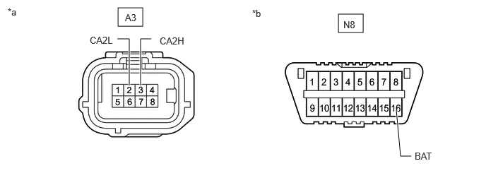
C350887C49
4.99,0.208 5.354,0.479 0.365,0.271 1.74,0.115 2.104,0.385 0.365,0.271 2.073,1.26 2.073,0.573 2.073,0.573 2.229,0.573 true 1.906,1.26 1.906,0.573 1.906,0.573 1.729,0.573 true 6.063,2.302 5.906,2.302 5.906,2.302 5.844,1.625 true 0.115,0.094 0.427,0.292 0.313,0.198 10 false *a 3.719,0.115 4.031,0.313 0.313,0.198 10 false *b 1.323,0.51 1.802,0.719 0.479,0.208 10 false CA2L 2.354,0.521 2.833,0.729 0.479,0.208 10 false CA2H 6.115,2.219 6.594,2.427 0.479,0.208 10 false BAT 5.063,0.281 5.385,0.479 0.323,0.198 10 false N8 1.844,0.177 2.167,0.375 0.323,0.198 10 false A3
*a Front view of wire harness connector
(to Millimeter Wave Radar Sensor Assembly)
*b Front view of DLC3


b.

Measure the resistance according to the value(s) in the table below.

Standard Resistance:
Tester Connection Condition Specified Condition
A3-3 (CA2H) - N8-16 (BAT) Cable disconnected from negative (-) battery terminal 6 kΩ or higher
A3-2 (CA2L) - N8-16 (BAT)


Result:
Proceed to
OK
NG


OK

NG

REPAIR OR REPLACE CAN BUS WIRE OR CONNECTOR (MILLIMETER WAVE RADAR SENSOR ASSEMBLY - NO. 9 CAN JUNCTION CONNECTOR)

47.CHECK FOR SHORT TO B+ IN CAN BUS WIRE (FORWARD RECOGNITION CAMERA - NO. 9 CAN JUNCTION CONNECTOR)
a.

Disconnect the a9 forward recognition camera connector.
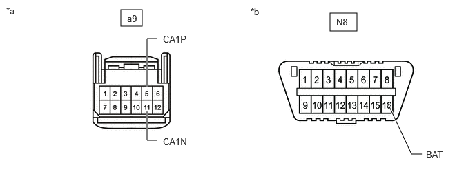
C350886C46
1.823,0.146 2.146,0.396 0.323,0.25 4.979,0.198 5.385,0.469 0.406,0.271 2.219,1.688 2.219,2.125 2.219,2.125 2.375,2.125 true 2.219,1.323 2.219,0.583 2.219,0.583 2.375,0.583 true 5.854,1.573 6.208,2.333 6.208,2.333 6.365,2.333 true 0.094,0.083 0.406,0.281 0.313,0.198 10 false *a 3.781,0.094 4.094,0.292 0.313,0.198 10 false *b 1.917,0.198 2.229,0.396 0.313,0.198 10 false a9 2.458,0.51 2.927,0.729 0.469,0.219 10 false CA1P 2.458,2.063 2.927,2.281 0.469,0.219 10 false CA1N 5.073,0.25 5.385,0.448 0.313,0.198 10 false N8 6.427,2.26 6.896,2.479 0.469,0.219 10 false BAT
*a Front view of wire harness connector
(to Forward Recognition Camera)
*b Front view of DLC3


b.

Measure the resistance according to the value(s) in the table below.

Standard Resistance:
Tester Connection Condition Specified Condition
a9-5 (CA1P) - N8-16 (BAT) Cable disconnected from negative (-) battery terminal 6 kΩ or higher
a9-11 (CA1N) - N8-16 (BAT)


Result:
Proceed to
OK
NG


OK

NG

REPAIR OR REPLACE CAN BUS WIRE OR CONNECTOR (FORWARD RECOGNITION CAMERA - NO. 9 CAN JUNCTION CONNECTOR)

48.CHECK FOR SHORT TO B+ IN CAN BUS WIRE (CLEARANCE WARNING ECU ASSEMBLY - NO. 9 CAN JUNCTION CONNECTOR)
a.

Disconnect the N48 clearance warning ECU assembly connector.
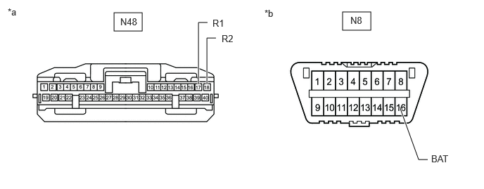
C350879C32
1.688,0.188 2.104,0.458 0.417,0.271 5.073,0.177 5.49,0.448 0.417,0.271 2.938,1.25 2.938,0.333 2.938,0.333 3.073,0.333 true 3.063,1.25 3.063,0.563 3.063,0.563 3.198,0.563 true 6.333,2.365 6.198,2.365 6.198,2.365 5.917,1.583 true 0.115,0.094 0.427,0.292 0.313,0.198 10 false *a 3.917,0.115 4.229,0.313 0.313,0.198 10 false *b 3.146,0.26 3.458,0.458 0.313,0.198 10 false R1 3.281,0.49 3.594,0.688 0.313,0.198 10 false R2 1.781,0.24 2.167,0.51 0.385,0.271 10 false N48 6.385,2.271 6.906,2.479 0.521,0.208 10 false BAT 5.188,0.219 5.573,0.49 0.385,0.271 10 false N8
*a Front view of wire harness connector
(to Clearance Warning ECU Assembly)
*b Front view of DLC3


b.

Measure the resistance according to the value(s) in the table below.

Standard Resistance:
Tester Connection Condition Specified Condition
N48-17 (R1) - N8-16 (BAT) Cable disconnected from negative (-) battery terminal 6 kΩ or higher
N48-18 (R2) - N8-16 (BAT)


c.

Reconnect the N48 clearance warning ECU assembly connector.


Result:
Proceed to
OK
NG


OK

NG

REPAIR OR REPLACE CAN BUS WIRE OR CONNECTOR (CLEARANCE WARNING ECU ASSEMBLY - NO. 9 CAN JUNCTION CONNECTOR)

49.CHECK FOR SHORT TO B+ IN CAN BUS WIRE (BLIND SPOT MONITOR SENSOR LH - NO. 12 CAN JUNCTION CONNECTOR)
a.

Disconnect the e2 blind spot monitor sensor LH connector.
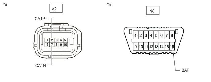
C350884C45
1.688,0.135 2.115,0.427 0.427,0.292 4.979,0.208 5.406,0.5 0.427,0.292 1.76,1.302 1.76,0.615 1.76,0.615 1.604,0.615 true 1.615,2.219 1.76,2.219 1.76,2.219 1.76,1.563 true 6.115,2.406 5.958,2.406 5.958,2.406 5.854,1.563 true 0.115,0.073 0.427,0.271 0.313,0.198 10 false *a 3.635,0.073 3.948,0.271 0.313,0.198 10 false *b 1.771,0.219 2.094,0.417 0.323,0.198 10 false e2 5.073,0.292 5.396,0.49 0.323,0.198 10 false N8 1.198,2.156 1.688,2.406 0.49,0.25 10 false CA1N 1.177,0.552 1.667,0.802 0.49,0.25 10 false CA1P 6.167,2.313 6.656,2.563 0.49,0.25 10 false BAT
*a Front view of wire harness connector
(to Blind Spot Monitor Sensor LH)
*b Front view of DLC3


b.

Measure the resistance according to the value(s) in the table below.

Standard Resistance:
Tester Connection Condition Specified Condition
e2-2 (CA1P) - N8-16 (BAT) Cable disconnected from negative (-) battery terminal 6 kΩ or higher
e2-7 (CA1N) - N8-16 (BAT)


c.

Reconnect the e2 blind spot monitor sensor LH connector.


Result:
Proceed to
OK
NG


OK

NG

REPAIR OR REPLACE CAN BUS WIRE OR CONNECTOR (BLIND SPOT MONITOR SENSOR LH - NO. 12 CAN JUNCTION CONNECTOR)

50.CHECK FOR SHORT TO B+ IN CAN BUS WIRE (TELEVISION CAMERA ASSEMBLY - NO. 12 CAN JUNCTION CONNECTOR)

*1: except Double Swing Out Type

*2: for Double Swing Out Type


a.

Disconnect the i7*1, k9*2 television camera assembly connector.

C387471
1.854,0.26 2.208,0.49 0.354,0.229 4.917,0.479 5.354,0.708 0.438,0.229 1.854,0.531 2.208,0.76 0.354,0.229 1.302,0.698 1.469,0.698 1.469,0.698 1.865,1.385 true 1.375,2.229 1.542,2.229 1.542,2.229 1.885,1.604 true 5.927,1.948 5.698,1.948 5.698,1.948 5.604,1.573 true 0.813,0.156 1.125,0.354 0.313,0.198 10 false *a 4.021,0.156 4.333,0.354 0.313,0.198 10 false *b 1.979,0.281 2.229,0.448 0.25,0.167 10 false i7 5.052,0.51 5.427,0.698 0.375,0.188 10 false N8 0.875,0.625 1.375,0.813 0.5,0.188 10 false CANL 0.938,2.156 1.427,2.365 0.49,0.208 10 false CANH 5.958,1.844 6.396,2.031 0.438,0.188 10 false BAT 2.25,0.292 2.5,0.458 0.25,0.167 10 false *A 1.958,0.563 2.208,0.729 0.25,0.167 10 false k9 2.25,0.542 2.5,0.708 0.25,0.167 10 false *B
*A except Double Swing Out Type *B for Double Swing Out Type
*a Front view of wire harness connector
(to Television Camera Assembly)
*b Front view of DLC3


b.

Measure the resistance according to the value(s) in the table below.

Standard Resistance:
Tester Connection Condition Specified Condition

*1: except Double Swing Out Type

*2: for Double Swing Out Type

i7-4 (CANH) - N8-16 (BAT)*1 Cable disconnected from negative (-) battery terminal 6 kΩ or higher
i7-1 (CANL) - N8-16 (BAT)*1
k9-4 (CANH) - N8-16 (BAT)*2 Cable disconnected from negative (-) battery terminal 6 kΩ or higher
k9-1 (CANL) - N8-16 (BAT)*2


Result:
Proceed to
OK
NG


OK

NG

REPAIR OR REPLACE CAN BUS WIRE OR CONNECTOR (TELEVISION CAMERA ASSEMBLY - NO. 12 CAN JUNCTION CONNECTOR)

51.CHECK FOR SHORT IN CAN BUS WIRES (CENTRAL GATEWAY ECU [NETWORK GATEWAY ECU] - NO. 9 CAN JUNCTION CONNECTOR)
a.
C368242C43
1.417,0.24 1.958,0.458 0.542,0.219 2.344,1.104 2.365,0.573 2.365,0.573 2.125,0.573 true 2.073,1.792 2.271,1.792 2.271,1.792 2.438,1.281 true 1.573,0.281 2.031,0.479 0.458,0.198 10 false N21 1.719,0.5 2.177,0.698 0.458,0.198 10 false CA1L 1.677,1.708 2.156,1.906 0.479,0.198 10 false CA1H 0.073,0.052 0.531,0.25 0.458,0.198 10 false *a
*a Front view of wire harness connector
(to Central Gateway ECU [Network Gateway ECU])


Disconnect the N21 central gateway ECU (network gateway ECU) connector.


b.

Measure the resistance according to the value(s) in the table below.

Standard Resistance:
Tester Connection Condition Specified Condition
N21-23 (CA1H) - N21-8 (CA1L) Cable disconnected from negative (-) battery terminal 108 to 132 Ω


c.

Reconnect the N21 central gateway ECU (network gateway ECU) connector.


Result:
Proceed to
OK
NG


OK

NG

52.CHECK FOR SHORT IN CAN BUS WIRE (NO. 3 CAN JUNCTION TERMINAL - NO. 12 CAN JUNCTION CONNECTOR)
a.
C369111C28
1.5,0.333 1.917,0.583 0.417,0.25 1.729,1.135 1.563,0.667 1.563,0.667 1.417,0.667 true 1.948,1.146 2.073,0.667 2.073,0.667 2.24,0.667 true 0.073,0.052 0.385,0.25 0.313,0.198 10 false *a 1.594,0.375 1.906,0.573 0.313,0.198 10 false Z24 2.281,0.604 2.771,0.865 0.49,0.26 10 false CANH 0.99,0.594 1.479,0.854 0.49,0.26 10 false CANL
*a Front view of wire harness connector
(to No. 3 CAN Junction Terminal)


Disconnect the Z24 No. 3 CAN junction terminal connector.


b.

Measure the resistance according to the value(s) in the table below.

Standard Resistance:
Tester Connection Condition Specified Condition
Z24-3 (CANH) - Z24-2 (CANL) Cable disconnected from negative (-) battery terminal 108 to 132 Ω


c.

Reconnect the Z24 No. 3 CAN junction terminal connector.


Result:
Proceed to
OK
NG


OK

REPLACE NO. 3 CAN JUNCTION TERMINAL

NG

53.CHECK FOR SHORT IN CAN BUS WIRE (NO. 9 CAN JUNCTION CONNECTOR - CENTRAL GATEWAY ECU [NETWORK GATEWAY ECU])
HINT:
·

Distinguish between the connectors connected to the No. 9 CAN junction connector by checking the color of the communication wire.

·

Before disconnecting the connectors, make a note of where it is connected.

·

Reconnect the connector to its original position.


a.

Disconnect the N222 No. 9 CAN junction connector.
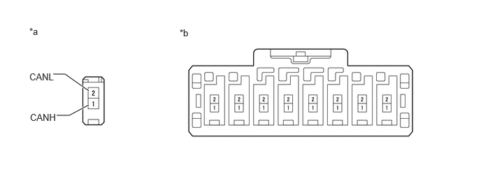
C423692C03
0.792,1.104 0.969,1.104 0.969,1.104 1.323,1.354 true 0.844,1.719 1.031,1.719 1.031,1.719 1.323,1.563 true 0.438,0.385 0.75,0.583 0.313,0.198 10 false *a 0.448,1.667 1.052,1.875 0.604,0.208 10 false CANH 0.438,1.063 0.948,1.271 0.51,0.208 10 false CANL 2.677,0.406 2.99,0.604 0.313,0.198 10 false *b
*a Vehicle wire harness connector connected to CAN junction connector *b Rear view of wire harness connector
(to No. 9 CAN Junction Connector)


b.

Measure the resistance according to the value(s) in the table below.
Standard Resistance:
Tester Connection Wiring Color Condition Specified Condition Connect to
N222-1 (CANH) - N222-2 (CANL) G - W Cable disconnected from negative (-) battery terminal 200 Ω or higher Central gateway ECU (network gateway ECU)


Result:
Proceed to
OK
NG


OK

54.CHECK VEHICLE TYPE

NG

REPAIR OR REPLACE CAN BUS WIRE OR CONNECTOR (NO. 9 CAN JUNCTION CONNECTOR - CENTRAL GATEWAY ECU [NETWORK GATEWAY ECU])

54.CHECK VEHICLE TYPE
a.

Check for vehicle type.


Result:
Result Proceed to
w/ Panoramic View Monitor System A
w/o Panoramic View Monitor System B


A

55.CHECK FOR SHORT IN CAN BUS WIRE (NO. 9 CAN JUNCTION CONNECTOR - PARKING ASSIST ECU)

B

56.CHECK VEHICLE TYPE
55.CHECK FOR SHORT IN CAN BUS WIRE (NO. 9 CAN JUNCTION CONNECTOR - PARKING ASSIST ECU)
HINT:
·

Distinguish between the connectors connected to the No. 9 CAN junction connector by checking the color of the communication wire.

·

Before disconnecting the connectors, make a note of where it is connected.

·

Reconnect the connector to its original position.


a.

Disconnect the N224 No. 9 CAN junction connector.

C423692C03
0.792,1.104 0.969,1.104 0.969,1.104 1.323,1.354 true 0.844,1.719 1.031,1.719 1.031,1.719 1.323,1.563 true 0.438,0.385 0.75,0.583 0.313,0.198 10 false *a 0.448,1.667 1.052,1.875 0.604,0.208 10 false CANH 0.438,1.063 0.948,1.271 0.51,0.208 10 false CANL 2.677,0.406 2.99,0.604 0.313,0.198 10 false *b
*a Vehicle wire harness connector connected to CAN junction connector *b Rear view of wire harness connector
(to No. 9 CAN Junction Connector)


b.

Measure the resistance according to the value(s) in the table below.
Standard Resistance:
Tester Connection Wiring Color Condition Specified Condition Connect to
N224-1 (CANH) - N224-2 (CANL) P - W Cable disconnected from negative (-) battery terminal 200 Ω or higher Parking assist ECU


Result:
Proceed to
OK
NG


OK

56.CHECK VEHICLE TYPE

NG

68.CHECK FOR SHORT IN CAN BUS WIRES (PARKING ASSIST ECU - NO. 9 CAN JUNCTION CONNECTOR)
56.CHECK VEHICLE TYPE
a.

Check for vehicle type.


Result:
Result Proceed to
w/ Pre-collision System A
w/o Pre-collision System B


A

57.CHECK FOR SHORT IN CAN BUS WIRE (NO. 9 CAN JUNCTION CONNECTOR - MILLIMETER WAVE RADAR SENSOR ASSEMBLY)

B

59.CHECK VEHICLE TYPE
57.CHECK FOR SHORT IN CAN BUS WIRE (NO. 9 CAN JUNCTION CONNECTOR - MILLIMETER WAVE RADAR SENSOR ASSEMBLY)
HINT:
·

Distinguish between the connectors connected to the No. 9 CAN junction connector by checking the color of the communication wire.

·

Before disconnecting the connectors, make a note of where it is connected.

·

Reconnect the connector to its original position.


a.

Disconnect the N226 No. 9 CAN junction connector.

C423692C03
0.792,1.104 0.969,1.104 0.969,1.104 1.323,1.354 true 0.844,1.719 1.031,1.719 1.031,1.719 1.323,1.563 true 0.438,0.385 0.75,0.583 0.313,0.198 10 false *a 0.448,1.667 1.052,1.875 0.604,0.208 10 false CANH 0.438,1.063 0.948,1.271 0.51,0.208 10 false CANL 2.677,0.406 2.99,0.604 0.313,0.198 10 false *b
*a Vehicle wire harness connector connected to CAN junction connector *b Rear view of wire harness connector
(to No. 9 CAN Junction Connector)


b.

Measure the resistance according to the value(s) in the table below.
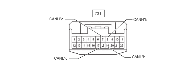
Standard Resistance:
Tester Connection Wiring Color Condition Specified Condition Connect to
N226-1 (CANH) - N226-2 (CANL) R - W Cable disconnected from negative (-) battery terminal 200 Ω or higher Millimeter wave radar sensor assembly


Result:
Proceed to
OK
NG


OK

58.CHECK FOR SHORT IN CAN BUS WIRE (NO. 9 CAN JUNCTION CONNECTOR - FORWARD RECOGNITION CAMERA)

NG

69.CHECK FOR SHORT IN CAN BUS WIRES (MILLIMETER WAVE RADAR SENSOR ASSEMBLY - NO. 9 CAN JUNCTION CONNECTOR)
58.CHECK FOR SHORT IN CAN BUS WIRE (NO. 9 CAN JUNCTION CONNECTOR - FORWARD RECOGNITION CAMERA)
HINT:
·

Distinguish between the connectors connected to the No. 9 CAN junction connector by checking the color of the communication wire.

·

Before disconnecting the connectors, make a note of where it is connected.

·

Reconnect the connector to its original position.


a.

Disconnect the N227 No. 9 CAN junction connector.

C423692C03
0.792,1.104 0.969,1.104 0.969,1.104 1.323,1.354 true 0.844,1.719 1.031,1.719 1.031,1.719 1.323,1.563 true 0.438,0.385 0.75,0.583 0.313,0.198 10 false *a 0.448,1.667 1.052,1.875 0.604,0.208 10 false CANH 0.438,1.063 0.948,1.271 0.51,0.208 10 false CANL 2.677,0.406 2.99,0.604 0.313,0.198 10 false *b
*a Vehicle wire harness connector connected to CAN junction connector *b Rear view of wire harness connector
(to No. 9 CAN Junction Connector)


b.

Measure the resistance according to the value(s) in the table below.
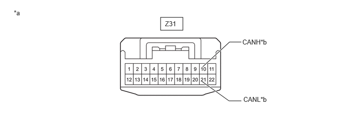
Standard Resistance:
Tester Connection Wiring Color Condition Specified Condition Connect to
N227-1 (CANH) - N227-2 (CANL) V - W Cable disconnected from negative (-) battery terminal 200 Ω or higher Forward recognition camera


Result:
Proceed to
OK
NG


OK

59.CHECK VEHICLE TYPE

NG

70.CHECK FOR SHORT IN CAN BUS WIRES (FORWARD RECOGNITION CAMERA - NO. 9 CAN JUNCTION CONNECTOR)
59.CHECK VEHICLE TYPE
a.

Check for vehicle type.


Result:
Result Proceed to
w/ TOYOTA Parking Assist-sensor System A
w/o TOYOTA Parking Assist-sensor System B


A

60.CHECK FOR SHORT IN CAN BUS WIRE (NO. 9 CAN JUNCTION CONNECTOR - CLEARANCE WARNING ECU ASSEMBLY)

B

61.CHECK FOR SHORT IN CAN BUS WIRE (NO. 9 CAN JUNCTION CONNECTOR - NO. 12 CAN JUNCTION CONNECTOR)
60.CHECK FOR SHORT IN CAN BUS WIRE (NO. 9 CAN JUNCTION CONNECTOR - CLEARANCE WARNING ECU ASSEMBLY)
HINT:
·

Distinguish between the connectors connected to the No. 9 CAN junction connector by checking the color of the communication wire.

·

Before disconnecting the connectors, make a note of where it is connected.

·

Reconnect the connector to its original position.


a.

Disconnect the N223 No. 9 CAN junction connector.

C423692C03
0.792,1.104 0.969,1.104 0.969,1.104 1.323,1.354 true 0.844,1.719 1.031,1.719 1.031,1.719 1.323,1.563 true 0.438,0.385 0.75,0.583 0.313,0.198 10 false *a 0.448,1.667 1.052,1.875 0.604,0.208 10 false CANH 0.438,1.063 0.948,1.271 0.51,0.208 10 false CANL 2.677,0.406 2.99,0.604 0.313,0.198 10 false *b
*a Vehicle wire harness connector connected to CAN junction connector *b Rear view of wire harness connector
(to No. 9 CAN Junction Connector)


b.

Measure the resistance according to the value(s) in the table below.

Standard Resistance:
Tester Connection Wiring Color Condition Specified Condition Connect to
N223-1 (CANH) - N223-2 (CANL) L - W Cable disconnected from negative (-) battery terminal 200 Ω or higher Clearance warning ECU assembly


Result:
Proceed to
OK
NG


OK

61.CHECK FOR SHORT IN CAN BUS WIRE (NO. 9 CAN JUNCTION CONNECTOR - NO. 12 CAN JUNCTION CONNECTOR)

NG

71.CHECK FOR SHORT IN CAN BUS WIRES (CLEARANCE WARNING ECU ASSEMBLY - NO. 9 CAN JUNCTION CONNECTOR)
61.CHECK FOR SHORT IN CAN BUS WIRE (NO. 9 CAN JUNCTION CONNECTOR - NO. 12 CAN JUNCTION CONNECTOR)
HINT:
·

Distinguish between the connectors connected to the No. 9 CAN junction connector by checking the color of the communication wire.

·

Before disconnecting the connectors, make a note of where it is connected.

·

Reconnect the connector to its original position.


a.

Disconnect the N225 No. 9 CAN junction connector.

C423692C03
0.792,1.104 0.969,1.104 0.969,1.104 1.323,1.354 true 0.844,1.719 1.031,1.719 1.031,1.719 1.323,1.563 true 0.438,0.385 0.75,0.583 0.313,0.198 10 false *a 0.448,1.667 1.052,1.875 0.604,0.208 10 false CANH 0.438,1.063 0.948,1.271 0.51,0.208 10 false CANL 2.677,0.406 2.99,0.604 0.313,0.198 10 false *b
*a Vehicle wire harness connector connected to CAN junction connector *b Rear view of wire harness connector
(to No. 9 CAN Junction Connector)


b.

Measure the resistance according to the value(s) in the table below.

Standard Resistance:
Tester Connection Wiring Color Condition Specified Condition Connect to
N225-1 (CANH) - N225-2 (CANL) P - W Cable disconnected from negative (-) battery terminal 200 Ω or higher No. 12 CAN junction connector


Result:
Proceed to
OK
NG


OK

REPLACE NO. 9 CAN JUNCTION CONNECTOR

NG

62.CHECK FOR SHORT IN CAN BUS WIRE (NO. 12 CAN JUNCTION CONNECTOR - NO. 9 CAN JUNCTION CONNECTOR)
a.

Disconnect the Z31 No. 12 CAN junction connector.


b.

Measure the resistance according to the value(s) in the table below.

C460022C35
3.375,0.365 3.823,0.625 0.448,0.26 4.458,1.385 4.854,1.021 4.854,1.021 5.021,1.021 true 4.458,1.688 4.854,1.906 4.854,1.906 5.104,1.906 true 3.469,0.417 3.927,0.615 0.458,0.198 10 false Z31 5.073,0.896 5.646,1.115 0.573,0.219 10 false CANH*b 5.156,1.802 5.729,2.021 0.573,0.219 10 false CANL*b 0.229,0.167 0.688,0.365 0.458,0.198 10 false *a
*a Front view of wire harness connector
(to No. 12 CAN Junction Connector)
*b to No. 9 CAN Junction Connector


Standard Resistance:
Tester Connection Condition Specified Condition Connect to
N31-11 (CANH) - N31-22 (CANL) Cable disconnected from negative (-) battery terminal 200 Ω or higher No. 9 CAN junction connector


Result:
Proceed to
OK
NG


OK

63.CHECK VEHICLE TYPE

NG

REPAIR OR REPLACE CAN BUS WIRE OR CONNECTOR (NO. 12 CAN JUNCTION CONNECTOR - NO. 9 CAN JUNCTION CONNECTOR)

63.CHECK VEHICLE TYPE
a.

Check for vehicle type.


Result:
Result Proceed to
w/ Blind Spot Monitor System A
w/o Blind Spot Monitor System B


A

64.CHECK FOR SHORT IN CAN BUS WIRE (NO. 12 CAN JUNCTION CONNECTOR - BLIND SPOT MONITOR SENSOR LH)

B

65.CHECK VEHICLE TYPE
64.CHECK FOR SHORT IN CAN BUS WIRE (NO. 12 CAN JUNCTION CONNECTOR - BLIND SPOT MONITOR SENSOR LH)
a.

Measure the resistance according to the value(s) in the table below.

C460022C39
3.375,0.365 3.823,0.625 0.448,0.26 4.115,1.385 4.771,0.823 4.771,0.823 4.979,0.823 true 4.115,1.708 4.615,2.125 4.615,2.125 4.833,2.125 true 3.469,0.417 3.927,0.615 0.458,0.198 10 false Z31 5.031,0.74 5.604,0.958 0.573,0.219 10 false CANH*b 4.885,2.01 5.458,2.229 0.573,0.219 10 false CANL*b 0.25,0.188 0.708,0.385 0.458,0.198 10 false *a
*a Front view of wire harness connector
(to No. 12 CAN Junction Connector)
*b to Blind Spot Monitor Sensor LH


Standard Resistance:
Tester Connection Condition Specified Condition Connect to
Z31-9 (CANH) - Z31-20 (CANL) Cable disconnected from negative (-) battery terminal 200 Ω or higher Blind spot monitor sensor LH


Result:
Proceed to
OK
NG


OK

65.CHECK VEHICLE TYPE

NG

72.CHECK FOR SHORT IN CAN BUS WIRES (BLIND SPOT MONITOR SENSOR LH - NO. 10 CAN JUNCTION CONNECTOR)
65.CHECK VEHICLE TYPE
a.

Check for vehicle type.


Result:
Result Proceed to
w/ Parking Assist Monitor System A
w/o Parking Assist Monitor System B


A

66.CHECK FOR SHORT IN CAN BUS WIRE (NO. 12 CAN JUNCTION CONNECTOR - TELEVISION CAMERA ASSEMBLY)

B

67.CHECK FOR SHORT IN CAN BUS WIRE (NO. 12 CAN JUNCTION CONNECTOR - NO. 3 CAN JUNCTION TERMINAL)
66.CHECK FOR SHORT IN CAN BUS WIRE (NO. 12 CAN JUNCTION CONNECTOR - TELEVISION CAMERA ASSEMBLY)

*1: except Double Swing Out Type

*2: for Double Swing Out Type
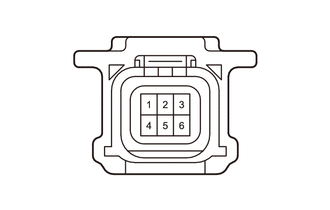

a.

Measure the resistance according to the value(s) in the table below.

C460022C41
3.375,0.365 3.823,0.625 0.448,0.26 3.938,1.375 4.625,0.719 4.625,0.719 4.844,0.719 true 3.938,1.729 4.552,2.115 4.552,2.115 4.781,2.115 true 3.771,1.365 2.719,0.708 2.719,0.708 2.365,0.708 true 3.76,1.708 2.844,2.167 2.844,2.167 2.521,2.167 true 3.469,0.417 3.927,0.615 0.458,0.198 10 false Z31 4.875,0.635 5.448,0.854 0.573,0.219 10 false CANH*b 4.823,2.01 5.396,2.229 0.573,0.219 10 false CANL*b 1.802,0.615 2.406,0.833 0.604,0.219 10 false CANH*c 1.979,2.063 2.552,2.281 0.573,0.219 10 false CANL*c
*a Front view of wire harness connector
(to No. 12 CAN Junction Connector)
*b to Television Camera Assembly (except Double Swing Out Type)
*c to Television Camera Assembly (for Double Swing Out Type) - -


Standard Resistance:
Tester Connection Condition Specified Condition Connect to

*1: except Double Swing Out Type

*2: for Double Swing Out Type

Z31-8 (CANH) - Z31-19 (CANL)*1 Cable disconnected from negative (-) battery terminal 200 Ω or higher Television camera assembly
Z31-7 (CANH) - Z31-18 (CANL)*2 Cable disconnected from negative (-) battery terminal 200 Ω or higher


Result:
Proceed to
OK
NG


OK

67.CHECK FOR SHORT IN CAN BUS WIRE (NO. 12 CAN JUNCTION CONNECTOR - NO. 3 CAN JUNCTION TERMINAL)

NG

73.CHECK FOR SHORT IN CAN BUS WIRES (TELEVISION CAMERA ASSEMBLY - NO. 10 CAN JUNCTION CONNECTOR)
67.CHECK FOR SHORT IN CAN BUS WIRE (NO. 12 CAN JUNCTION CONNECTOR - NO. 3 CAN JUNCTION TERMINAL)
a.

Measure the resistance according to the value(s) in the table below.

C460022C42
3.375,0.365 3.844,0.635 0.469,0.271 4.26,1.406 4.823,0.885 4.823,0.885 5.073,0.885 true 4.25,1.719 4.813,2.125 4.813,2.125 5.073,2.125 true 3.469,0.417 3.927,0.615 0.458,0.198 10 false Z31 5.094,0.802 5.667,1.021 0.573,0.219 10 false CANH*b 5.115,2.01 5.719,2.24 0.604,0.229 10 false CANL*b 0.292,0.188 0.75,0.385 0.458,0.198 10 false *a
*a Front view of wire harness connector
(to No. 12 CAN Junction Connector)
*b to No. 3 CAN Junction Terminal


Standard Resistance:
Tester Connection Condition Specified Condition Connect to
Z31-10 (CANH) - Z31-21 (CANL) Cable disconnected from negative (-) battery terminal 200 Ω or higher No. 3 CAN junction terminal


Result:
Proceed to
OK
NG


OK

REPLACE NO. 12 CAN JUNCTION CONNECTOR

NG

REPAIR OR REPLACE CAN BUS WIRE OR CONNECTOR (NO. 12 CAN JUNCTION CONNECTOR - NO. 3 CAN JUNCTION TERMINAL)

68.CHECK FOR SHORT IN CAN BUS WIRES (PARKING ASSIST ECU - NO. 9 CAN JUNCTION CONNECTOR)
a.
C369149
1.5,0.5 1.917,0.75 0.417,0.25 2.583,2.667 2.75,2.667 2.75,2.667 3.156,1.833 true 2.583,0.833 2.75,0.833 2.75,0.833 3.167,1.583 true 0.083,0.073 0.396,0.271 0.313,0.198 10 false *a 2.188,0.771 2.802,0.948 0.615,0.177 10 false CANL 1.563,0.531 1.99,0.781 0.427,0.25 10 false N151 2.146,2.583 2.688,2.781 0.542,0.198 10 false CANH
*a Front view of wire harness connector
(to Parking Assist ECU)


Disconnect the N151 parking assist ECU connector.


b.

Measure the resistance according to the value(s) in the table below.

Standard Resistance:
Tester Connection Condition Specified Condition
N151-40 (CANH) - N151-18 (CANL) Cable disconnected from negative (-) battery terminal 54 to 69 Ω


c.

Reconnect the N151 parking assist ECU connector.


Result:
Proceed to
OK
NG


OK

NG

REPAIR OR REPLACE CAN BUS WIRE OR CONNECTOR (PARKING ASSIST ECU - NO. 9 CAN JUNCTION CONNECTOR)

69.CHECK FOR SHORT IN CAN BUS WIRES (MILLIMETER WAVE RADAR SENSOR ASSEMBLY - NO. 9 CAN JUNCTION CONNECTOR)
a.
C346951C95
1.49,0.156 1.854,0.365 0.365,0.208 2.365,0.396 2.198,0.396 2.198,0.396 1.792,1.073 true 0.917,0.396 1.115,0.396 1.115,0.396 1.604,1.073 true 0.115,0.083 0.427,0.24 0.313,0.156 10 false *a 1.594,0.188 1.927,0.427 0.333,0.24 10 false A3 2.458,0.333 3.063,0.573 0.604,0.24 10 false CA2H 0.479,0.333 0.938,0.531 0.458,0.198 10 false CA2L
*a Front view of wire harness connector
(to Millimeter Wave Radar Sensor Assembly)


Disconnect the A3 millimeter wave radar sensor assembly connector.


b.

Measure the resistance according to the value(s) in the table below.

Standard Resistance:
Tester Connection Condition Specified Condition
A3-3 (CA2H) - A3-2 (CA2L) Cable disconnected from negative (-) battery terminal 54 to 69 Ω


Result:
Proceed to
OK
NG


OK

NG

REPAIR OR REPLACE CAN BUS WIRE OR CONNECTOR (MILLIMETER WAVE RADAR SENSOR ASSEMBLY - NO. 9 CAN JUNCTION CONNECTOR)

70.CHECK FOR SHORT IN CAN BUS WIRES (FORWARD RECOGNITION CAMERA - NO. 9 CAN JUNCTION CONNECTOR)
a.
C386793C12
1.49,0.104 1.875,0.375 0.385,0.271 1.948,1.198 1.948,0.458 1.948,0.458 2.104,0.458 true 1.958,1.521 1.958,1.917 1.958,1.917 2.115,1.917 true 0.083,0.094 0.417,0.323 0.333,0.229 10 false *a 1.594,0.167 1.927,0.396 0.333,0.229 10 false a9 2.167,0.354 2.615,0.604 0.448,0.25 10 false CA1P 2.167,1.813 2.615,2.063 0.448,0.25 10 false CA1N
*a Front view of wire harness connector
(to Forward Recognition Camera)


Disconnect the a9 forward recognition camera connector.


b.

Measure the resistance according to the value(s) in the table below.

Standard Resistance:
Tester Connection Condition Specified Condition
a9-5 (CA1P) - a9-11 (CA1N) Cable disconnected from negative (-) battery terminal 54 to 69 Ω


Result:
Proceed to
OK
NG


OK

NG

REPAIR OR REPLACE CAN BUS WIRE OR CONNECTOR (FORWARD RECOGNITION CAMERA - NO. 9 CAN JUNCTION CONNECTOR)

71.CHECK FOR SHORT IN CAN BUS WIRES (CLEARANCE WARNING ECU ASSEMBLY - NO. 9 CAN JUNCTION CONNECTOR)
a.
C369149C49
1.5,0.5 1.917,0.75 0.417,0.25 2.5,1 2.667,1 2.667,1 3.01,1.604 true 2.583,0.833 2.75,0.833 2.75,0.833 3.167,1.583 true 0.083,0.073 0.396,0.271 0.313,0.198 10 false *a 2.313,0.938 2.625,1.135 0.313,0.198 10 false R1 2.406,0.76 2.719,0.958 0.313,0.198 10 false R2 1.604,0.531 1.917,0.729 0.313,0.198 10 false N48
*a Front view of wire harness connector
(to Clearance Warning ECU Assembly)


Disconnect the N48 clearance warning ECU assembly connector.


b.

Measure the resistance according to the value(s) in the table below.

Standard Resistance:
Tester Connection Condition Specified Condition
N48-17 (R1) - N48-18 (R2) Cable disconnected from negative (-) battery terminal 54 to 69 Ω


c.

Reconnect the N48 clearance warning ECU assembly connector.


Result:
Proceed to
OK
NG


OK

NG

REPAIR OR REPLACE CAN BUS WIRE OR CONNECTOR (CLEARANCE WARNING ECU ASSEMBLY - NO. 9 CAN JUNCTION CONNECTOR)

72.CHECK FOR SHORT IN CAN BUS WIRES (BLIND SPOT MONITOR SENSOR LH - NO. 10 CAN JUNCTION CONNECTOR)
a.
C369127C12
1.5,0.417 1.917,0.667 0.417,0.25 1.531,1.844 1.833,2.5 1.833,2.5 2,2.5 true 1.552,1.656 1.75,1 1.75,1 1.917,1 true 1.969,0.938 2.427,1.135 0.458,0.198 10 false CA1P 0.125,0.135 0.583,0.333 0.458,0.198 10 false *a 2.021,2.438 2.479,2.635 0.458,0.198 10 false CA1N 1.594,0.469 2.052,0.667 0.458,0.198 10 false e2
*a Front view of wire harness connector
(to Blind Spot Monitor Sensor LH)


Disconnect the e2 blind spot monitor sensor LH connector.


b.

Measure the resistance according to the value(s) in the table below.

Standard Resistance:
Tester Connection Condition Specified Condition
e2-2 (CA1P) - e2-7 (CA1N) Cable disconnected from negative (-) battery terminal 54 to 69 Ω


c.

Reconnect the e2 blind spot monitor sensor LH connector.


Result:
Proceed to
OK
NG


OK

NG

REPAIR OR REPLACE CAN BUS WIRE OR CONNECTOR (BLIND SPOT MONITOR SENSOR LH - NO. 10 CAN JUNCTION CONNECTOR)

73.CHECK FOR SHORT IN CAN BUS WIRES (TELEVISION CAMERA ASSEMBLY - NO. 10 CAN JUNCTION CONNECTOR)

*1: except Double Swing Out Type

*2: for Double Swing Out Type


a.
C407715
0.979,0.083 1.385,0.292 0.406,0.208 1.677,0.083 2.083,0.292 0.406,0.208 0.688,1.656 0.854,1.656 0.854,1.656 1.542,1.313 true 0.583,0.729 0.729,0.729 0.729,0.729 1.542,1.073 true 0.073,0.083 0.385,0.24 0.313,0.156 10 false *a 1.094,0.115 1.406,0.271 0.313,0.156 10 false i7 0.26,1.583 0.75,1.75 0.49,0.167 10 false CANH 0.208,0.656 0.698,0.823 0.49,0.167 10 false CANL 1.427,0.104 1.74,0.26 0.313,0.156 10 false *A 1.792,0.104 2.104,0.26 0.313,0.156 10 false k9 2.135,0.115 2.448,0.271 0.313,0.156 10 false *B
*A except Double Swing Out Type
*B for Double Swing Out Type
*a Front view of wire harness connector
(to Television Camera Assembly)


Disconnect the i7*1, k9*2 television camera assembly connector.


b.

Measure the resistance according to the value(s) in the table below.

Standard Resistance:
Tester Connection Condition Specified Condition

*1: except Double Swing Out Type

*2: for Double Swing Out Type

i7-4 (CANH) - i7-1 (CANL)*1 Cable disconnected from negative (-) battery terminal 54 to 69 Ω
k9-4 (CANH) - k9-1 (CANL)*2 Cable disconnected from negative (-) battery terminal 54 to 69 Ω


Result:
Proceed to
OK
NG


OK

NG

REPAIR OR REPLACE CAN BUS WIRE OR CONNECTOR (TELEVISION CAMERA ASSEMBLY - NO. 12 CAN JUNCTION CONNECTOR)

74.CHECK FOR OPEN IN CAN BUS WIRE (CENTRAL GATEWAY ECU [NETWORK GATEWAY ECU] - NO. 9 CAN JUNCTION CONNECTOR)
a.
C368242C43
1.417,0.24 1.958,0.458 0.542,0.219 2.344,1.104 2.365,0.573 2.365,0.573 2.125,0.573 true 2.073,1.792 2.271,1.792 2.271,1.792 2.438,1.281 true 1.573,0.281 2.031,0.479 0.458,0.198 10 false N21 1.719,0.5 2.177,0.698 0.458,0.198 10 false CA1L 1.677,1.708 2.156,1.906 0.479,0.198 10 false CA1H 0.073,0.052 0.531,0.25 0.458,0.198 10 false *a
*a Front view of wire harness connector
(to Central Gateway ECU [Network Gateway ECU])


Disconnect the N21 central gateway ECU (network gateway ECU) connector.


b.

Measure the resistance according to the value(s) in the table below.

Standard Resistance:
Tester Connection Condition Specified Condition
N21-23 (CA1H) - N21-8 (CA1L) Cable disconnected from negative (-) battery terminal 108 to 132 Ω


c.

Reconnect the N21 central gateway ECU (network gateway ECU) connector.


Result:
Proceed to
OK
NG


OK

NG

75.CHECK FOR OPEN IN CAN BUS WIRE (NO. 3 CAN JUNCTION TERMINAL - NO. 12 CAN JUNCTION CONNECTOR)
a.
C369111C28
1.5,0.333 1.917,0.583 0.417,0.25 1.729,1.135 1.563,0.667 1.563,0.667 1.417,0.667 true 1.948,1.146 2.073,0.667 2.073,0.667 2.24,0.667 true 0.073,0.052 0.385,0.25 0.313,0.198 10 false *a 1.594,0.375 1.906,0.573 0.313,0.198 10 false Z24 2.281,0.604 2.771,0.865 0.49,0.26 10 false CANH 0.99,0.594 1.479,0.854 0.49,0.26 10 false CANL
*a Front view of wire harness connector
(to No. 3 CAN Junction Terminal)


Disconnect the Z24 No. 3 CAN junction terminal connector.


b.

Measure the resistance according to the value(s) in the table below.

Standard Resistance:
Tester Connection Condition Specified Condition
Z24-3 (CANH) - Z24-2 (CANL) Cable disconnected from negative (-) battery terminal 108 to 132 Ω


c.

Reconnect the Z24 No. 3 CAN junction terminal connector.


Result:
Proceed to
OK
NG


OK

REPLACE NO. 3 CAN JUNCTION TERMINAL

NG

76.CHECK FOR OPEN IN CAN BUS WIRE (NO. 9 CAN JUNCTION CONNECTOR - CENTRAL GATEWAY ECU [NETWORK GATEWAY ECU])
HINT:
·

Distinguish between the connectors connected to the No. 9 CAN junction connector by checking the color of the communication wire.

·

Before disconnecting the connectors, make a note of where it is connected.

·

Reconnect the connector to its original position.


a.

Disconnect the N222 No. 9 CAN junction connector.

C423692C03
0.792,1.104 0.969,1.104 0.969,1.104 1.323,1.354 true 0.844,1.719 1.031,1.719 1.031,1.719 1.323,1.563 true 0.438,0.385 0.75,0.583 0.313,0.198 10 false *a 0.448,1.667 1.052,1.875 0.604,0.208 10 false CANH 0.438,1.063 0.948,1.271 0.51,0.208 10 false CANL 2.677,0.406 2.99,0.604 0.313,0.198 10 false *b
*a Vehicle wire harness connector connected to CAN junction connector *b Rear view of wire harness connector
(to No. 9 CAN Junction Connector)


b.

Measure the resistance according to the value(s) in the table below.

Standard Resistance:
Tester Connection Wiring Color Condition Specified Condition Connect to
N222-1 (CANH) - N222-2 (CANL) G - W Cable disconnected from negative (-) battery terminal 108 to 132 Ω Central gateway ECU (network gateway ECU)


c.

Reconnect the N222 No. 9 CAN junction connector.


Result:
Proceed to
OK
NG


OK

77.CHECK FOR OPEN IN CAN BUS WIRE (NO. 9 CAN JUNCTION CONNECTOR - NO. 12 CAN JUNCTION CONNECTOR)

NG

REPAIR OR REPLACE CAN BUS WIRE OR CONNECTOR (NO. 9 CAN JUNCTION CONNECTOR - CENTRAL GATEWAY ECU [NETWORK GATEWAY ECU])

77.CHECK FOR OPEN IN CAN BUS WIRE (NO. 9 CAN JUNCTION CONNECTOR - NO. 12 CAN JUNCTION CONNECTOR)
HINT:
·

Distinguish between the connectors connected to the No. 9 CAN junction connector by checking the color of the communication wire.

·

Before disconnecting the connectors, make a note of where it is connected.

·

Reconnect the connector to its original position.


a.

Disconnect the N225 No. 9 CAN junction connector.

C423692C03
0.792,1.104 0.969,1.104 0.969,1.104 1.323,1.354 true 0.844,1.719 1.031,1.719 1.031,1.719 1.323,1.563 true 0.438,0.385 0.75,0.583 0.313,0.198 10 false *a 0.448,1.667 1.052,1.875 0.604,0.208 10 false CANH 0.438,1.063 0.948,1.271 0.51,0.208 10 false CANL 2.677,0.406 2.99,0.604 0.313,0.198 10 false *b
*a Vehicle wire harness connector connected to CAN junction connector *b Rear view of wire harness connector
(to No. 9 CAN Junction Connector)


b.

Measure the resistance according to the value(s) in the table below.

Standard Resistance:
Tester Connection Wiring Color Condition Specified Condition Connect to
N225-1 (CANH) - N225-2 (CANL) P - W Cable disconnected from negative (-) battery terminal 108 to 132 Ω No. 12 CAN junction connector


c.

Reconnect the 225 No. 9 CAN junction connector.


Result:
Proceed to
OK
NG


OK

REPLACE NO. 9 CAN JUNCTION CONNECTOR

NG

78.CHECK FOR OPEN IN CAN BUS WIRE (NO. 12 CAN JUNCTION CONNECTOR - NO. 9 CAN JUNCTION CONNECTOR)
a.

Disconnect the Z31 No. 12 CAN junction connector.


b.

Measure the resistance according to the value(s) in the table below.

C460022C35
3.375,0.365 3.823,0.625 0.448,0.26 4.458,1.385 4.854,1.021 4.854,1.021 5.021,1.021 true 4.458,1.688 4.854,1.906 4.854,1.906 5.104,1.906 true 3.469,0.417 3.927,0.615 0.458,0.198 10 false Z31 5.073,0.896 5.646,1.115 0.573,0.219 10 false CANH*b 5.156,1.802 5.729,2.021 0.573,0.219 10 false CANL*b 0.229,0.167 0.688,0.365 0.458,0.198 10 false *a
*a Front view of wire harness connector
(to No. 12 CAN Junction Connector)
*b to No. 9 CAN Junction Connector


Standard Resistance:
Tester Connection Condition Specified Condition Connect to
N31-11 (CANH) - N31-22 (CANL) Cable disconnected from negative (-) battery terminal 108 to 132 Ω No. 9 CAN junction connector


Result:
Proceed to
OK
NG


OK

79.CHECK FOR OPEN IN CAN BUS WIRE (NO. 12 CAN JUNCTION CONNECTOR - NO. 3 CAN JUNCTION TERMINAL)

NG

REPAIR OR REPLACE CAN BUS WIRE OR CONNECTOR (NO. 12 CAN JUNCTION CONNECTOR - NO. 9 CAN JUNCTION CONNECTOR)

79.CHECK FOR OPEN IN CAN BUS WIRE (NO. 12 CAN JUNCTION CONNECTOR - NO. 3 CAN JUNCTION TERMINAL)
a.

Measure the resistance according to the value(s) in the table below.

C460022C42
3.375,0.365 3.844,0.635 0.469,0.271 4.26,1.406 4.823,0.885 4.823,0.885 5.073,0.885 true 4.25,1.719 4.813,2.125 4.813,2.125 5.073,2.125 true 3.469,0.417 3.927,0.615 0.458,0.198 10 false Z31 5.094,0.802 5.667,1.021 0.573,0.219 10 false CANH*b 5.115,2.01 5.719,2.24 0.604,0.229 10 false CANL*b 0.292,0.188 0.75,0.385 0.458,0.198 10 false *a
*a Front view of wire harness connector
(to No. 12 CAN Junction Connector)
*b to No. 3 CAN Junction Terminal


Standard Resistance:
Tester Connection Condition Specified Condition Connect to
Z31-10 (CANH) - Z31-21 (CANL) Cable disconnected from negative (-) battery terminal 108 to 132 Ω No. 3 CAN junction terminal


Result:
Proceed to
OK
NG


OK

REPLACE NO. 12 CAN JUNCTION CONNECTOR

NG

REPAIR OR REPLACE CAN BUS WIRE OR CONNECTOR (NO. 12 CAN JUNCTION CONNECTOR - NO. 3 CAN JUNCTION TERMINAL)