PARK ASSIST / MONITORING TELEVISION CAMERA(for Rear) REMOVAL
CAUTION / NOTICE / HINT
The necessary procedures (adjustment, calibration, initialization, or registration) that must be performed after parts are removed, installed, or replaced during the television camera assembly removal/installation are shown below.
| Replacement part or procedure | Necessary procedures | Effect/Inoperative Function When Necessary Procedures are not Performed | Link |
|---|---|---|---|
| Television camera assembly (Including removal and installation) | ·
Parking assist monitor system initialization ·
Television camera assembly optical axis (Back camera position setting) |
Parking assist monitor system | ( 201902,999999,_56,_079315,_0385736,RM100000001GNRB,) 201902,999999,_56,_079315,_0385736,RM100000001GNRB,)
|
| Television camera view adjustment (Rear adjustment) | Panoramic view monitor system | (201906,999999,_56,_079315,_0396274,RM100000001IGR4,)
|
|
·
Front television camera assembly, radiator grille assembly or front bumper assembly ·
Television camera assembly ·
Side television camera assembly LH or outer rear view mirror assembly LH ·
Side television camera assembly RH or outer rear view mirror assembly RH |
Television camera view adjustment (Adjustment of all cameras)
|
Panoramic view monitor system | (201906,999999,_56,_079315,_0396274,RM100000001IGR4,)
|
PROCEDURE

 76801
1.REMOVE BACK DOOR OUTSIDE GARNISH SUB-ASSEMBLY
76801
1.REMOVE BACK DOOR OUTSIDE GARNISH SUB-ASSEMBLY
86790
2.REMOVE TELEVISION CAMERA ASSEMBLY (w/ Parking Assist Monitor System)
w/ Digital Inner Mirror:
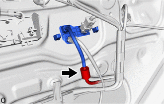
Disconnect the washer hose.
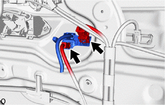
Disconnect the 2 connectors.
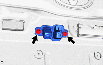
Remove the 2 screws.
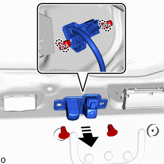
| *1 | Screw Grommet |

|
Remove in this Direction |
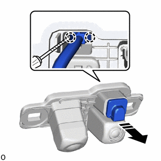
Using pliers, grip the claw of the 2 screw grommets and slide the 2 screw grommets to remove the television camera assembly and 2 screw grommets as shown in the illustration.
|
|
Remove in this Direction |

|
Protective Tape |
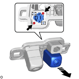
Using a thin-bladed screwdriver with its tip wrapped with protective tape, detach the claw and remove the camera cleaner nozzle assembly.
|
|
Remove in this Direction |
Remove the 2 screws.
Detach the guide and remove the inner mirror camera assembly as shown in the illustration.
w/o Digital Inner Mirror:
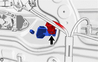
Disconnect the connector.
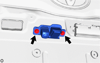
Remove the 2 screws.
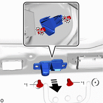
| *1 | Screw Grommet |
|
|
Remove in this Direction |
Using pliers, grip the claw of the 2 screw grommets and slide the 2 screw grommets to remove the television camera assembly and 2 screw grommets as shown in the illustration.
for Double Swing Out Type:
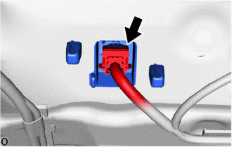
Disconnect the connector.
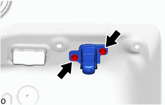
Remove the 2 screws.
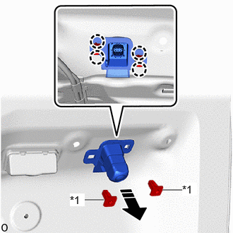
| *1 | Screw Grommet |
|
|
Remove in this Direction |
Using pliers, grip the claw of the 2 screw grommets and slide the 2 screw grommets to remove the television camera assembly and 2 screw grommets as shown in the illustration.
86790
3.REMOVE TELEVISION CAMERA ASSEMBLY (w/o Parking Assist Monitor System)
- HINT:
-
Use the same procedure for the television camera assembly (w/ Parking Assist Monitor System).