AUDIO / VIDEO AUDIO AND VISUAL SYSTEM(for Radio and Display Type) B15C3 Speaker Output Short
DESCRIPTION
This DTC is stored when a malfunction occurs in the speakers.
| DTC No. | Detection Item | DTC Detection Condition | Trouble Area |
|---|---|---|---|
| B15C3 | Speaker Output Short | A short is detected in the speaker output circuit | ·
Harness or connector ·
Speakers ·
Radio and display receiver assembly |
WIRING DIAGRAM
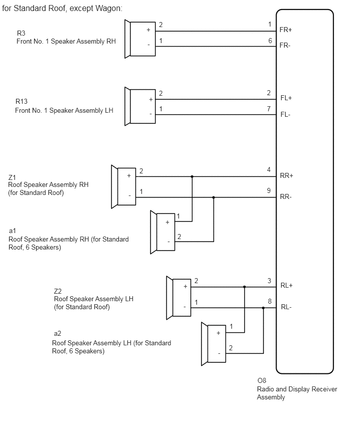
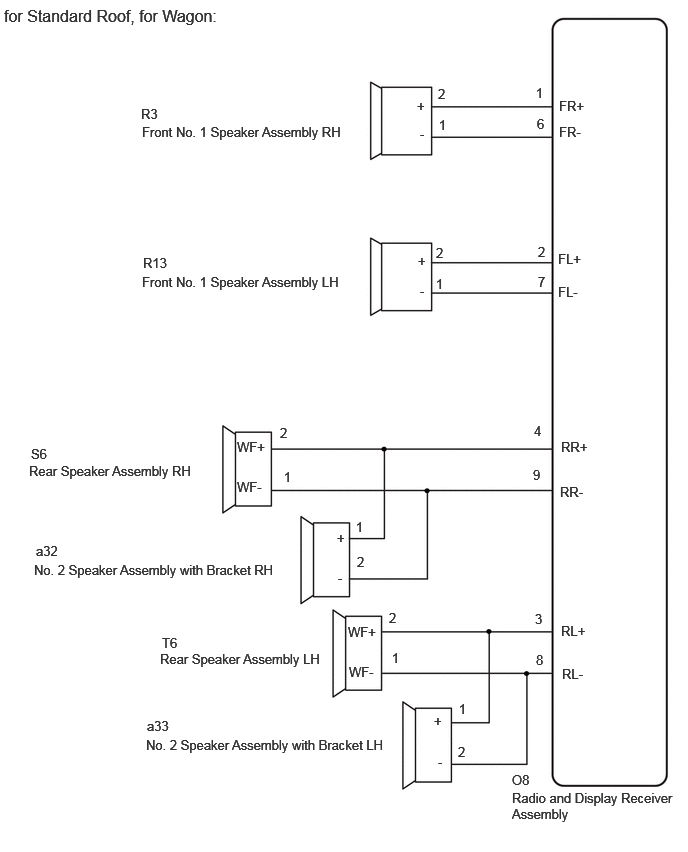
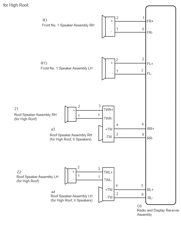
CAUTION / NOTICE / HINT
- NOTICE:
-
When replacing the radio and display receiver assembly, always replace it with a new one. If a radio and display receiver assembly which was installed to another vehicle is used, the following may occur:
- ·
A communication malfunction DTC may be stored.
·The radio and display receiver assembly may not operate normally.
- HINT:
-
Depending on the parts that are replaced during vehicle inspection or maintenance, performing initialization, registration or calibration may be needed. Refer to Precaution for Audio and Visual System.
PROCEDURE
Clear the DTCs.
- Body Electrical > Navigation System > Clear DTCs
- 50002 212
Recheck for DTCs and check that no DTCs are output.
- Body Electrical > Navigation System > Trouble Codes
- 50001 212
- OK:
No DTCs are output.
- Result:
Proceed to OK NG
OK
NG
Choose the model to be inspected.
- Result:
Result Proceed to for Standard Roof A for High Roof B
A
B
Choose the model to be inspected.
- Result:
Result Proceed to except Wagon A for Wagon B
A
B
Disconnect the O8 radio and display receiver assembly connector.
Disconnect the R3 and R13 front No. 1 speaker assembly connectors.
Disconnect the Z1 and Z2 roof speaker assembly (for Standard Roof) connectors.
Disconnect the a1 and a2 roof speaker assembly (for Standard Roof, 6 Speakers) connectors.
Measure the resistance according to the value(s) in the table below.
- Standard Resistance:
Tester Connection Condition Specified Condition O8-1 (FR+) - R3-2 (+) Always Below 1 Ω O8-6 (FR-) - R3-1 (-) Always Below 1 Ω O8-2 (FL+) - R13-2 (+) Always Below 1 Ω O8-7 (FL-) - R13-1 (-) Always Below 1 Ω O8-4 (RR+) - Z1-2 (+) Always Below 1 Ω O8-9 (RR-) - Z1-1 (-) Always Below 1 Ω O8-3 (RL+) - Z2-2 (+) Always Below 1 Ω O8-8 (RL-) - Z2-1 (-) Always Below 1 Ω O8-4 (RR+) - a1-1 (+) Always Below 1 Ω O8-9 (RR-) - a1-2 (-) Always Below 1 Ω O8-3 (RL+) - a2-1 (+) Always Below 1 Ω O8-8 (RL-) - a2-2 (-) Always Below 1 Ω O8-1 (FR+) - Body ground Always 10 kΩ or higher O8-6 (FR-) - Body ground Always 10 kΩ or higher O8-2 (FL+) - Body ground Always 10 kΩ or higher O8-7 (FL-) - Body ground Always 10 kΩ or higher O8-4 (RR+) - Body ground Always 10 kΩ or higher O8-9 (RR-) - Body ground Always 10 kΩ or higher O8-3 (RL+) - Body ground Always 10 kΩ or higher O8-8 (RL-) - Body ground Always 10 kΩ or higher
- Result:
Proceed to OK NG
OK
NG
Remove the front No. 1 speaker assembly.
Inspect the front No. 1 speaker assembly.
- Result:
Proceed to OK NG
OK
NG
Remove the roof speaker assembly (for Standard Roof).
Inspect the roof speaker assembly (for Standard Roof).
- Result:
Proceed to OK NG
OK
NG
Replace the roof speaker assembly (for Standard Roof, 6 Speakers) with a new or known good one.
Clear the DTCs.
- Body Electrical > Navigation System > Clear DTCs
- 50002 212
Recheck for DTCs and check that no DTCs are output.
- Body Electrical > Navigation System > Trouble Codes
- 50001 212
- HINT:
- ·
Connect all the connectors to the roof speaker assemblies that were disconnected.
·When there is a possibility that either the right or left roof speaker is defective, inspect by interchanging the right one with the left one.
·Perform the above inspection on both LH and RH sides.
- OK:
No DTCs are output.
- Result:
Proceed to OK NG
OK
NG
Disconnect the O8 radio and display receiver assembly connector.
Disconnect the R3 and R13 front No. 1 speaker assembly connectors.
Disconnect the S6 and T6 rear speaker assembly connectors.
Disconnect the a32 and a33 No. 2 speaker assembly with bracket connectors.
Measure the resistance according to the value(s) in the table below.
- Standard Resistance:
Tester Connection Condition Specified Condition O8-1 (FR+) - R3-2 (+) Always Below 1 Ω O8-6 (FR-) - R3-1 (-) Always Below 1 Ω O8-2 (FL+) - R13-2 (+) Always Below 1 Ω O8-7 (FL-) - R13-1 (-) Always Below 1 Ω O8-4 (RR+) - S6-2 (WF+) Always Below 1 Ω O8-9 (RR-) - S6-1 (WF-) Always Below 1 Ω O8-3 (RL+) - T6-2 (WF+) Always Below 1 Ω O8-8 (RL-) - T6-1 (WF-) Always Below 1 Ω O8-4 (RR+) - a32-1 (+) Always Below 1 Ω O8-9 (RR-) - a32-2 (-) Always Below 1 Ω O8-3 (RL+) - a33-1 (+) Always Below 1 Ω O8-8 (RL-) - a33-2 (-) Always Below 1 Ω O8-1 (FR+) - Body ground Always 10 kΩ or higher O8-6 (FR-) - Body ground Always 10 kΩ or higher O8-2 (FL+) - Body ground Always 10 kΩ or higher O8-7 (FL-) - Body ground Always 10 kΩ or higher O8-4 (RR+) - Body ground Always 10 kΩ or higher O8-9 (RR-) - Body ground Always 10 kΩ or higher O8-3 (RL+) - Body ground Always 10 kΩ or higher O8-8 (RL-) - Body ground Always 10 kΩ or higher
- Result:
Proceed to OK NG
OK
NG
Remove the front No. 1 speaker assembly.
Inspect the front No. 1 speaker assembly.
- Result:
Proceed to OK NG
OK
NG
Remove the rear speaker assembly.
Inspect the rear speaker assembly.
- Result:
Proceed to OK NG
OK
NG
Replace the No. 2 speaker assembly with bracket with a new or known good one.
Clear the DTCs.
- Body Electrical > Navigation System > Clear DTCs
- 50002 212
Recheck for DTCs and check that no DTCs are output.
- Body Electrical > Navigation System > Trouble Codes
- 50001 212
- HINT:
- ·
Connect all the connectors to the roof speaker assemblies that were disconnected.
·When there is a possibility that either the right or left roof speaker is defective, inspect by interchanging the right one with the left one.
·Perform the above inspection on both LH and RH sides.
- OK:
No DTCs are output.
- Result:
Proceed to OK NG
OK
NG
Disconnect the O8 radio and display receiver assembly connector.
Disconnect the R3 and R13 front No. 1 speaker assembly connectors.
Disconnect the Z1 and Z2 roof speaker assembly (for High Roof) connectors.
Disconnect the a3 and a4 roof speaker assembly (for High Roof, 6 Speakers) connectors.
Measure the resistance according to the value(s) in the table below.
- Standard Resistance:
Tester Connection Condition Specified Condition O8-1 (FR+) - R3-2 (+) Always Below 1 Ω O8-6 (FR-) - R3-1 (-) Always Below 1 Ω O8-2 (FL+) - R13-2 (+) Always Below 1 Ω O8-7 (FL-) - R13-1 (-) Always Below 1 Ω O8-4 (RR+) - a3-4 (+TW) Always Below 1 Ω O8-9 (RR-) - a3-2 (-TW) Always Below 1 Ω a3-3 (TWR+) - Z1-2 (+) Always Below 1 Ω a3-1 (TWR-) - Z1-1 (-) Always Below 1 Ω O8-3 (RL+) - a4-4 (+TW) Always Below 1 Ω O8-8 (RL-) - a4-2 (-TW) Always Below 1 Ω a4-3 (TWL+) - Z2-2 (+) Always Below 1 Ω a4-1 (TWL-) - Z2-1 (-) Always Below 1 Ω O8-1 (FR+) - Body ground Always 10 kΩ or higher O8-6 (FR-) - Body ground Always 10 kΩ or higher O8-2 (FL+) - Body ground Always 10 kΩ or higher O8-7 (FL-) - Body ground Always 10 kΩ or higher O8-4 (RR+) - Body ground Always 10 kΩ or higher O8-9 (RR-) - Body ground Always 10 kΩ or higher a3-3 (TWR+) - Body ground Always 10 kΩ or higher a3-1 (TWR-) - Body ground Always 10 kΩ or higher O8-3 (RL+) - Body ground Always 10 kΩ or higher O8-8 (RL-) - Body ground Always 10 kΩ or higher a4-3 (TWL+) - Body ground Always 10 kΩ or higher a4-1 (TWL-) - Body ground Always 10 kΩ or higher
- Result:
Proceed to OK NG
OK
NG
Remove the front No. 1 speaker assembly.
Inspect the front No. 1 speaker assembly.
- Result:
Proceed to OK NG
OK
NG
Remove the roof speaker assembly (for High Roof).
Inspect the roof speaker assembly (for High Roof).
- Result:
Proceed to OK NG
OK
NG
Replace the roof speaker assembly (for High Roof, 6 Speakers) with a new or known good one.
Clear the DTCs.
- Body Electrical > Navigation System > Clear DTCs
- 50002 212
Recheck for DTCs and check that no DTCs are output.
- Body Electrical > Navigation System > Trouble Codes
- 50001 212
- HINT:
- ·
Connect all the connectors to the roof speaker assemblies that were disconnected.
·When there is a possibility that either the right or left roof speaker is defective, inspect by interchanging the right one with the left one.
·Perform the above inspection on both LH and RH sides.
- OK:
No DTCs are output.
- Result:
Proceed to OK NG
OK
NG